Magnetic Hall Effect Sensor Arduino Programming, Interfacing & applications
Last Updated on August 18, 2024 by Engr. Shahzada Fahad
Table of Contents
Description:
Magnetic Hall Effect Sensor Arduino Programming, Interfacing & applications– In this Tutorial you will learn how to use the Magnetic Hall Effect sensor with Arduino. This Tutorial covers the extreme basics like for example.
- What is a Magnetic Hall Effect Sensor?
- Types of the Magnetic Hall Effect Sensor.
- Applications of the Magnetic Hall Effect Sensor.
- Hall Effect Sensor Pinout.
- Magnetic Hall Effect Sensor Interfacing with the Arduino.
- Magnetic Hall Effect Sensor Arduino programming.
If you are a beginner and you really want to master the Magnetic Hall-effect Sensor then this tutorial is for you. At the end of this tutorial, you will be able to detect the presence of a Magnetic and control anything you want. I have already used this Hall Effect sensor in a Tongue controlled wheelchair; and also in an Electronic Glove designed for the Hand Protection.
Note: for the step by step explanation watch video tutorial given at the end.
Without any further delay, let’s get started!!!
Amazon Links:
Arduino Nano USB-C Type (Recommended)
*Disclosure: These are affiliate links. As an Amazon Associate I earn from qualifying purchases.
Today we have thousands of different types of Sensors and every sensor has a different application. Every sensor is designed in a way that it converts the real-world data into the digital/analog data so that it can be processed by the electronic circuits and microcontrollers. The selection of a Sensor entirely depends on your requirement. As this tutorial is about the Magnetic Hall Effect Sensor so I will stick with the examples of the projects in which Hall Effect Sensor can be used.
Let’s, for example, we want to measure the RPM of a rotating disk. Now, this can be done using a laser, IR LEDs, encoders, and a Magnetic Hall Effect sensor. It depends on the situation which sensor you should go for. I am not saying that for a rotating disk or wheel only the Magnetic Hall Effect Sensor should be used, but there are situations when the laser, infrared sensor, etc fail to work. I will practically explain this in a video clip. In which I designed a protective glove. I actually designed this for a client.
What is a Magnetic Hall Effect Sensor?
A Hall Effect Sensor is a transducer that varies its output voltage in response to a magnetic field. Hall Effect Sensors are used for Proximity switching, Positioning, Speed detection, and current sensing applications.
Types of the Magnetic Hall Effect Sensor:
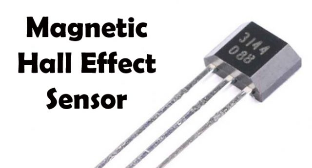
If you search on Google you will find so many types of the Magnetic Hall Effect Sensor. The one you can see in the picture below is the Magnetic Hall Effect Sensor that we will be using today; I will explain why I have selected this one.

The sensor which you can see in the picture below is also the Magnetic Hall Effect sensor.
If you are a beginner and you are not comfortable with soldering and some extra connections. Then my recommendation is to use the readymade module.
Now I am going to explain why I have selected the Keyes Magnetic Hall effect sensor. As you can see it’s a complete module the soldering is already done, this module has the male headers and moreover, this module has the Digital output and also the analog output. While in the market there are some types that give you only the digital output. The Magnetic Hall Effect Sensor module that I am using in this tutorial is best and you should go for this one.
Applications of the Magnetic Hall Effect Sensor:
Security system:
You can make a security system using the Hall Effect Sensor. For example, you want to monitor a door for this the Hall Effect sensor is the best choice. You can simply fix a permanent magnet on the door and the Hall Effect sensor board on the door frame. This way each time the door is opened a buzzer will turn ON or you can send a message to the owner. This way it can be used in cupboards, lockers, Cars, etc.
RPM measurement:
As I said in the beginning, the Magnetic Hall Effect sensor can also be used for the RPM; again it really depends on the situation. The sensor I am using in this tutorial can also give you the digital output. the digital output pin “D0” of the Magnetic hall effect sensor can be connected with the Arduino’s interrupt Pin so each time the magnet is detected it will give a signal on the interrupt pin; which of course we can count.
Speed Measurement:
The Magnetic Hall Effect sensor is also best for measuring the speed. Let’s say you want to measure the speed of a bicycle in kilometers, in a situation like this you can use a permanent magnet on the wheel and the magnetic Hall Effect sensor on the frame. So each time the cycle wheel completes one revolution, it will signal the microcontroller. These revolutions can be counted and then using a formula the distance covered and the speed can be calculated.
Touchless Control system:
The Magnetic Hall Effect Sensor is also ideal for locations where you want to control an electrical load without the physical contact. It can be used in bathrooms a Magnetic Hall Effect sensor can be used inside the wall and when you bring a magnet near to the wall the load will turn on.
Magnetic Hall Effect Sensor Pinout:

As you can see clearly this Magnetic Hall Effect Sensor Module has a total of 4 male headers which are clearly labeled with A0, G, +, and D0.
A0 is the analog output which gives you different values as per the magnetic field. Which is the best feature of this module, depending on the field strength you can turn ON or Turn of an electrical load or do anything else. So this pin should be connected with any of the analog pins of the Arduino or Mega.
G pin of the module is the ground pin and it should be connected with the Arduino’s GND.
+ Pin of the module is the voltage pin and it should be connected with the Arduino’s 5 volts.
D0 pin is the digital output pin and it can be connected with any I/O pin of the Arduino or Mega.
Apart from the male headers, if you see clearly this Hall Effect sensor also has a variable resistor that is used to set a certain threshold voltage. So each time this voltage is reached the module gives a High signal. This variation of voltage is due to the magnetic field. This module also has an LED that turns ON and Turns OFF as the module detects a magnet.
Magnetic Hall Effect Sensor Arduino Circuit Diagram:
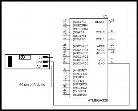
The circuit diagram is really simple. As you can see the module 5v pin which is the + pin is connected with the Arduino’s 5v. The ground is connected with the Arduino’s ground while the A0 pin of the Hall Effect Sensor is connected with the A0 pin of the Arduino.
Magnetic Hall Effect Sensor Interfacing with Arduino:
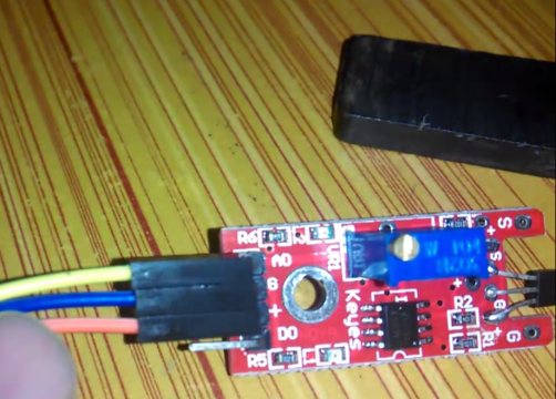
For the easy interfacing, I connected male to female type jumper wires. As you can see the yellow wire is connected with the A0 pin, the Blue wire is connected with the ground and orange wire is connected with the + pin.
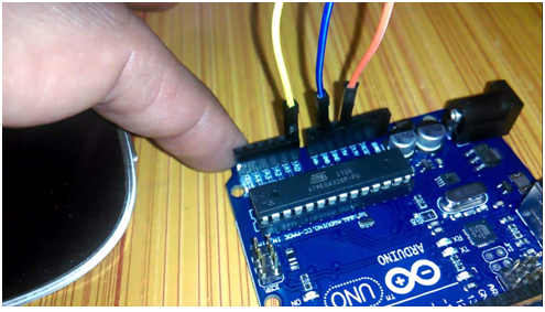
The Yellow, Blue, and Orange wires are connected with the Arduino’s A0, ground and 5v.
Magnetic Hall Effect Sensor Arduino Programming:
This is a very simple program. The purpose of this program is to find how near or far is the magnet from the Hall Effect Sensor. To demonstrate this I am going to control the Arduino’s onboard led which is available on pin number 13. This LED turns ON and Turns off as the magnetic gets near and far from the sensor.
|
1 2 3 4 5 6 7 8 9 10 11 12 13 14 15 16 17 18 19 20 21 22 23 24 25 26 27 28 29 30 |
int halls = A0; int led = 13; int data = 0; void setup() { Serial.begin(9600); pinMode(halls, INPUT); pinMode(led, OUTPUT); digitalWrite(led, LOW); } void loop() { data = analogRead(halls); Serial.print("Sensor data:"); Serial.println(data); Delay(1000); if(data < 500 ) { digitalWrite(led, HIGH); } if(data > 500 ) { digitalWrite(led, LOW); }else delay(100); } |
Program Explanation:
First of all, I started off by defining the Pins.
The Hall Effect Sensor is connected with the analog pin A0 of the Arduino.
int halls = A0;
int led = 13;
I am using the Arduino’s onboard led.
int data = 0;
data is a variable of the type integer and will be used for storing the value of the Hall Effect Sensor.
Every Arduino and Mega program has at least two functions which are the void setup and void loop functions. The void setup function executes only one time while the void loop function executes infinite times. This function keeps running until you turn off the Arduino.
void setup() {
Serial.begin(9600); // activates the serial communication while 9600 is the baud rate. You should select the same baud rate on the serial monitor window.
pinMode(halls, INPUT); // set sensor as the input
pinMode(led, OUTPUT); // set LED as the output.
digitalWrite(led, LOW); // Turn OFF the LED.
}
void loop() {
data = analogRead(halls);
first we read the Hall Effect Sensor using the AnalogRead function and store the value in variable data.
Serial.print(“Sensor data:”);
Serial.println(data); // this function sends the value to the serial monitor
Delay(1000); // 1000 milli seconds are equal to 1 second.
Using the if conditions the LED is turned ON and turned OFF. The value stored in data changes as we bring the magnet near to the Hall Effect sensor or we take it away from the sensor.
if(data < 500 )
{
digitalWrite(led, HIGH);
}
if(data > 500 )
{
digitalWrite(led, LOW);
}else
delay(100);
}
After you are done with the programming and you have successfully compiled the program then the next step is to upload the program into the Arduino or Mega. I am using the word Mega because the same program and connections will also work with the Mega. So it doesn’t matter if you use the Arduino Uno or Mega. So After you are done with the program uploading then click on the Serial Monitor button, this will open the window.
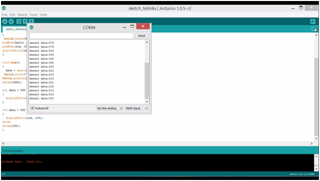
On the Serial monitor, you will be able to see different values as you bring the magnet near the sensor or you take it away. You will also be able to control the LED; this LED should turn ON and turn OFF.
Electrical Gloves for workers Protection Video Demonstration:
As you can see in the video above, this is a complete wireless system. You can see when my hand is near to the plastic part which can be considered as the machine moving part, one light turns off while the other light turns on; which is a demonstration that the machine is turned off and the buzzer is activated. Such gloves can be a life saver in industries. I designed this prototype model for a client. Very soon I will make a complete tutorial on this. You can subscribe to my website and also to my YouTube channel. This way you will never miss any of my upcoming tutorials.
Watch Video Tutorial:
Discover more from Electronic Clinic
Subscribe to get the latest posts sent to your email.


Hello Shahzada. Would you be able to modify this circuit to power an LM3014N LED driver? Using the Analog Out function of the sensor, as you move the magnet across the sensor’s path, the corresponding LED from 1 to 10 would indicate where the magnet is.