MLX90614 non-contact infrared temperature sensor using Arduino, Emissivity Calibration
Last Updated on September 21, 2024 by Engr. Shahzada Fahad
Table of Contents
MLX90614 non-contact infrared temperature:
MLX90614 non-contact infrared temperature sensor using Arduino, Emissivity Calibration– In this article, you will learn how to make a contactless Temperature monitoring system using MLX90614 non-contact infrared temperature sensor, Arduino, and SSD1306 i2c supported Oled display module. This is the Gravity I2C supported Non-contact IR Temperature sensor which I recently got from the DFrobot. This is a medical-grade Non-contact temperature sensor and offers an accuracy of ±0.2˚C in a limited temperature range around the Human body temperature.
As a standard, the MLX90614 is calibrated for an object emissivity of 1. I have seen guys completely ignoring the emissivity value when using the MLX90614 infrared temperature sensor. Let me first explain what is Emissivity and then I will practically explain what happens when you ignore the Emissivity value.
Emissivity:
Emissivity is a measure of the efficiency in which a surface emits thermal energy. It is defined as the fraction of energy being emitted relative to that emitted by a thermally black surface or a black body. A black body is a material that is a perfect emitter of heat energy and has an emissivity value of 1. A material with an emissivity value of 0 would be considered a perfect thermal mirror.
For example, if an object had the potential to emit 100 units of energy but only emits 90 units in the real world, then that object would have an emissivity value of 0.90. In the real world, there are no perfect “black bodies” and very few perfect infrared mirrors so most objects have an emissivity between 0 and 1.
Different objects have different emissivity values and when you ignore the emissivity value then you will end up getting the wrong temperature readings. As I said earlier, as a standard, the MLX90614 is calibrated for an object emissivity of 1. So, let’s say if you want to measure the temperature of a human body then you will need to recalibrate your MLX90614 non-contact infrared temperature sensor. Let me practically show you.
Download Emissivity Values Table.
MLX90614 without Calibration:
During my first test, I am completely ignoring the emissivity value and I am going with the standard Emissivity value of 1. To check how accurate is the temperature reading of the MLX90614, first, I am going to measure the temperature of my hand using a surface contact-based temperature sensor DS18b20.
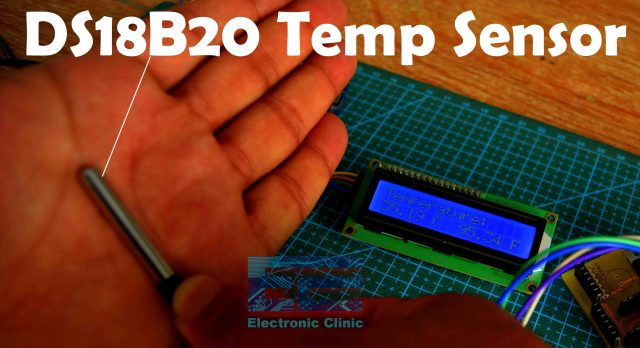
You can see the temperature is around 35 Celsius.
Now, I am going to measure the temperature using MLX90614 and an Arduino-based thermometer. Let’s see if the MLX90614 IR Sensor is going to give me the same temperature.
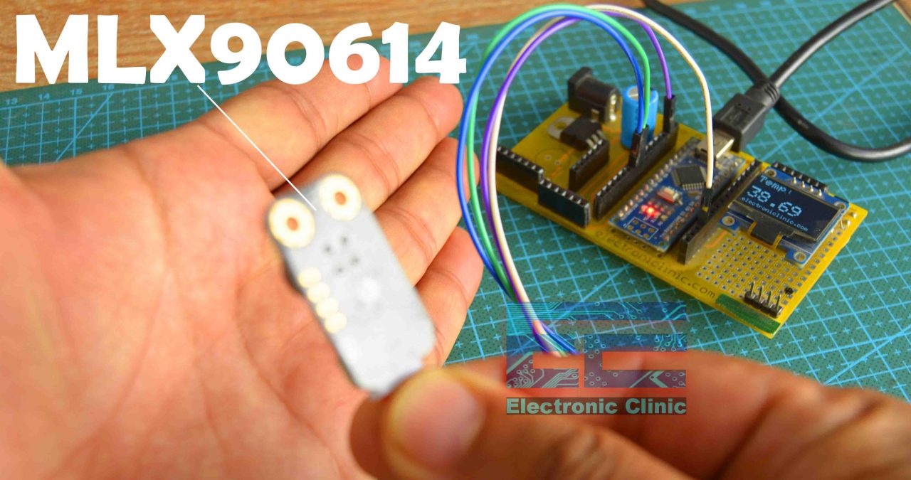
You can see the temperature is around 38.69 Celsius, which is not accurate because I am using the Emissivity value of 1, while the emissivity value of the Human skin is between 0.95 and 0.98.
MLX90614 Calibration using Emissivity value:
Now, I am going to measure the temperature using my Calibrated MLX90614 non-contact infrared temperature sensor. I am using the emissivity value of 0.98.

You can see the temperature is 34.91 Celsius, which is pretty close to the temperature measured with the DS18b20 Sensor.
This small difference in temperature, which you can see; can be due to the sensor itself as it has the temperature accuracy between ±0.2℃ and ±0.5℃. For the initial calibration using a standard temperature meter as a reference. Anyways, a small temperature difference is not a big deal, you can always fine-tune the values using calibration factor value in the programming.
If your target surface is particularly reflective, or if you need a higher level of accuracy on your readings, consider verifying the emissivity of a surface with the help of a surface probe and meter as I demonstrated.
Using a chart value as a starting point, adjust the emissivity setting on your infrared thermometer up and down until the temperature reading on your infrared thermometer matches the temperature recorded by the surface probe and meter.
I further fine-tuned the emissivity value and then I was simply amazed at the accuracy.

The temperature of the cutting mat measured by the DS18B20 is 28.19 Celsius and the same exact temperature value I also got from the MLX90614. You need to spend some time on adjusting the Emissivity value if you want this level of accuracy from your IR Temperature sensor.
Anyways, I checked the temperature of other objects with their suggested Emissivity values and the results were quite impressive. Later in this article, I will explain how to change the Emissivity value.
Now, you have got an idea of what exactly you are going to learn after reading this article. So, without any further delay, let’s get started!!!
Amazon Links:
Arduino Nano USB-C Type (Recommended)
MLX90614 non-contact infrared temperature sensor
DS18B20 One-wire waterproof digital temperature sensor
*Disclosure: These are affiliate links. As an Amazon Associate I earn from qualifying purchases.
MLX90614 IR Temperature Sensor:
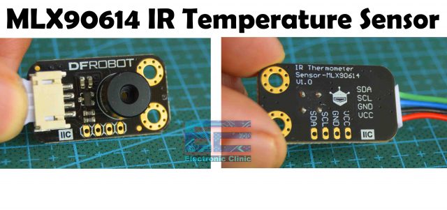
This is the Gravity MLX90614 non-contact infrared Temperature Sensor from DFrobot, due to its large field of view (FOV = 35°), it is more suitable for commercial application. The non-contact measurement uses infrared radiation to measure the temperature and does not require direct contact or touch. The operating voltage is 3.3 volts to 5 volts. The measurement accuracy is between ±0.2℃ and ±0.5℃. The temperature range is from -70.01℃ to +380℃ with 0.01℃ resolution. Its interface type is I2C and it weighs around 15 grams. For more technical details read my article, you can find a link in the description. Now, let’s take a look at the circuit diagram.
This module measures the surface temperature by detecting infrared radiation energy and wavelength distribution. The IR temperature probe consists of an optical system, photoelectric detector, amplifier, signal processing, and output module. The optical system collects the infrared radiation in its field of view and the infrared radiation energy is converted into corresponding electrical signals when converging on the photoelectric detector. After being processed by the amplifier and signal processing circuit, the signal is converted into a temperature value. The MLX90614 is self-calibrating and has a low noise amplifier integrated into the signal processing chip. The chip itself is a 17 bit ADC and DSP device, giving accurate and reliable results.
MLX90614 Specifications:
SPECIFICATION
Model: MLX90614-DCC
Operating Voltage: 3.3V – 5V
Measurement Accuracy: ±0.2℃(body temperature range)/ ±0.5℃
Temperature: -70.01℃ to +380℃, (0.01 ℃ resolution)
Interface Type: I2C
Interface Line Sequence: VCC, GND, SCL, SDA
FOV: 35°
Dimensions: 31.5*18 mm/1.24 x 0.7 inches
Weight: 15g
MLX90614 Interfacing with Arduino, Circuit Diagram:
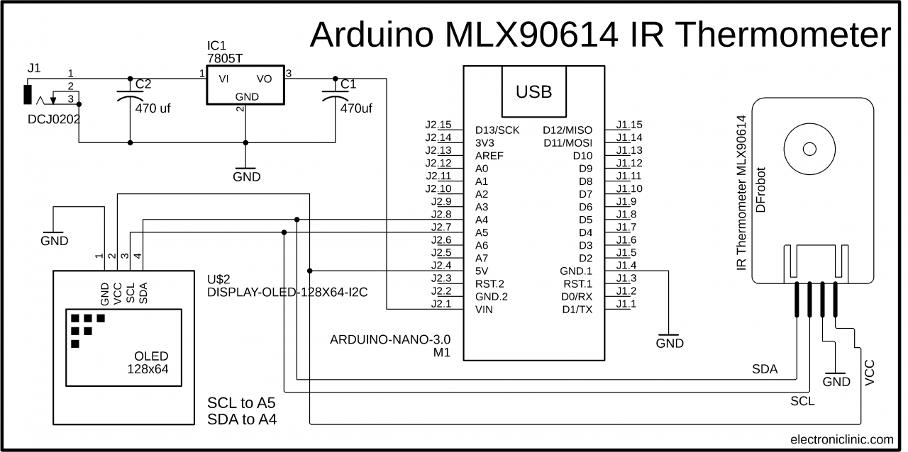
The MLX90614 IR thermometer sensor and the SSD1306 Oled display module both are I2C supported devices. The SCL and SDA pins of both the modules are connected with the A5 and A4 pins. A5 is the SCL and A4 is the SDA. While the VCC and GND pins of both the modules are connected with the 5V and ground. These are the minimal connections that you will need to test everything. If you don’t want to use your computer to power up the Arduino then you can use an external 5v power supply.
On the top left side is the regulated 5V power supply based on the LM7805 voltage regulated. J1 is the DC female power jack and this is where we connect our 12 volts dc power supply. You can also use a battery or a solar panel. Make sure you keep the voltage below 28 volts.
Calibrating MLX90614 Temperature Sensor:
The datasheet for the MLX90614 has information on emissivity corrections. The correction can be applied after you make the measurement – there is no need to update the sensor. For the record, you need to acquire both the ambient (chip) temperature Ta, and the object temperature Tom in Kelvin as measured by the sensor.
The corrected object temperature Toc is given by the following expression in C, where eps is the surface emissivity:
Toc = pow( ( ( (pow(Tom,4)-pow(Ta,4))/eps) + pow(Ta,4) ), 0.25);
For very shiny objects (emissivity < 0.1), correction is usually not possible and contactless temperature measurements become impractical or impossible. But, you don’t have to do it yourself. In the code given below, you can do it easily.
MLX90614 Arduino Programming:
|
1 2 3 4 5 6 7 8 9 10 11 12 13 14 15 16 17 18 19 20 21 22 23 24 25 26 27 28 29 30 31 32 33 34 35 36 37 38 39 40 41 42 43 44 45 46 47 48 49 50 51 52 53 54 55 56 57 58 59 60 61 62 63 64 65 66 67 68 69 70 71 72 73 74 75 76 77 78 79 80 81 82 83 84 85 86 87 88 89 90 |
#include <DFRobot_MLX90614.h> #include <Wire.h> #include <Adafruit_GFX.h> #include <Adafruit_SSD1306.h> //sda A4 scl a5 #define SCREEN_WIDTH 128 // OLED display width, in pixels #define SCREEN_HEIGHT 64 // OLED display height, in pixels // Declaration for an SSD1306 display connected to I2C (SDA, SCL pins) #define OLED_RESET -1 // Reset pin # (or -1 if sharing Arduino reset pin) Adafruit_SSD1306 display(SCREEN_WIDTH, SCREEN_HEIGHT, &Wire, OLED_RESET); DFRobot_MLX90614_IIC sensor; // instantiate an object to drive our sensor void setup() { Serial.begin(115200); display.begin(SSD1306_SWITCHCAPVCC, 0x3C); delay(2000); display.clearDisplay(); display.setTextColor(WHITE); // initialize the sensor while( NO_ERR != sensor.begin() ){ Serial.println("Communication with device failed, please check connection"); delay(3000); } Serial.println("Begin ok!"); /** * adjust sensor sleep mode * mode select to enter or exit sleep mode, it's enter sleep mode by default * true is to enter sleep mode * false is to exit sleep mode (automatically exit sleep mode after power down and restart) */ sensor.enterSleepMode(); delay(50); sensor.enterSleepMode(false); delay(200); sensor.setEmissivityCorrectionCoefficient(.98); float ambientTemp = sensor.getAmbientTempCelsius(); float objectTemp = sensor.getObjectTempCelsius(); } void loop() { /** * get ambient temperature, unit is Celsius * return value range: -40 C ~ 85 C */ float ambientTemp = sensor.getAmbientTempCelsius(); /** * get temperature of object 1, unit is Celsius * return value range: -40 C ~ 85 C */ float objectTemp = sensor.getObjectTempCelsius(); // print measured data in Celsius Serial.print("Ambient celsius : "); Serial.print(ambientTemp); Serial.println(" C"); Serial.print("Object celsius : "); Serial.print(objectTemp); Serial.println(" C"); display.clearDisplay(); // display R G B Values display.setTextSize(2); display.setCursor(0,0); display.print("Temp:"); display.setTextSize(3); display.setCursor(0, 28); display.print(objectTemp); display.setTextSize(1); display.setCursor(0, 56); display.print("www.electroniclinic.com"); display.display(); // print measured data in Fahrenheit Serial.print("Ambient fahrenheit : "); Serial.print(ambientTemp*9/5 + 32); Serial.println(" F"); Serial.print("Object fahrenheit : "); Serial.print(objectTemp*9/5 + 32); Serial.println(" F"); delay(1000); } |
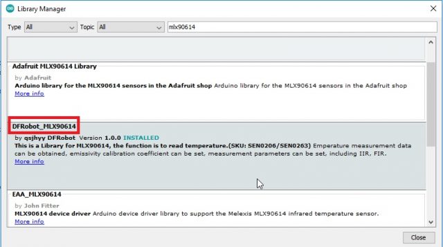
Before you start the programming, first of all make sure you download the DFRobot_MLX90614 library. Click on the sketch menu, go to Include Library, and then click on the Manage Libraries. Search for the MLX90614, Install the DFRobot_MLX90614.
You will also need to download these other libraries
|
1 2 3 |
#include <Wire.h> #include <Adafruit_GFX.h> #include <Adafruit_SSD1306.h> |
In the same way, you can download these libraries from my article on the Oled display module.
This is just a simple code, the only thing that you need to take care of is this Emissivity correction co-efficient value.
|
1 |
sensor.setEmissivityCorrectionCoefficient(.98); |
Right now I am using a .98 value. I checked the header file and found, it’s just the correction factor value, you can play with this value until your temperature reading matches with the temperature of another standard sensor that you are using as the reference. The rest of the code is pretty straightforward, we read the ambient temperature, the object temperature, and then print these values on the serial monitor and also on the Oled display Module. So, that’s all about the programming.
DS18B20 with Arduino Circuit Diagram:

DS18B20 Arduino Programming:
|
1 2 3 4 5 6 7 8 9 10 11 12 13 14 15 16 17 18 19 20 21 22 23 24 25 26 27 28 29 30 31 32 33 34 35 36 37 38 39 40 41 42 43 44 45 46 47 48 49 |
#include <OneWire.h> #include <DallasTemperature.h> #include <LiquidCrystal_I2C.h> LiquidCrystal_I2C lcd(0x27,16,2); //0x27 is the i2c address, while 16 = columns, and 2 = rows. #define ONE_WIRE_BUS 7 OneWire oneWire(ONE_WIRE_BUS); DallasTemperature sensors(&oneWire); float Celcius=0; float Fahrenheit=0; void setup(void) { Serial.begin(9600); sensors.begin(); // set up the LCD's number of columns and rows: lcd.init(); //Init the LCD lcd.backlight(); //Activate backlight lcd.clear(); } void loop(void) { sensors.requestTemperatures(); Celcius=sensors.getTempCByIndex(0); Fahrenheit=sensors.toFahrenheit(Celcius); Serial.print(" C "); Serial.print(Celcius); Serial.print(" F "); Serial.println(Fahrenheit); delay(500); lcd.setCursor(0, 0); lcd.print("Temperature:"); lcd.setCursor(0, 1); lcd.print(Celcius); lcd.setCursor(6, 1); lcd.print("C"); lcd.setCursor(9, 1); lcd.print(Fahrenheit); lcd.setCursor(15, 1); lcd.print("F"); } |
Watch Video Tutorial:

Discover more from Electronic Clinic
Subscribe to get the latest posts sent to your email.


