Multiple Transmitters and Single Receiver for Monitoring Sensors Using Lora
Last Updated on August 17, 2024 by Engr. Shahzada Fahad
Table of Contents
Multiple Transmitters and Single Receiver, Description:
Multiple Transmitters and Single Receiver for Monitoring Sensors Using Lora- I have been using Lora Transceiver modules from the Reyax Technologies in different types of monitoring and control system projects.
Reyax rylr890 LoRa 15km 915MHz RF Transceiver connection and AT commands
This is a getting started tutorial and explains how to use AT commands.
Sensor Monitoring using Lora by Reyax rylr890/rylr896 and Arduino
This tutorial explains how to monitor a single sensor.
Reyax Lora based Multiple Sensors Monitoring using Arduino
This tutorial explains how to monitor multiple sensors connected with the same Arduino.
ESP8266 Lora based IoT Smart Irrigation System with Cell Phone App
In this tutorial the ESP8266 Nodemcu module is used as the gateway. The transmitter side sends the sensors values to the receiver side and then data is sent to the cell phone app through wifi.
Long Range RC Plane Transmitter and Receiver 15Km Lora by Reyax Rylr896
In this tutorial, I have explained how to design a long-range controller for the RC Plane.
The first three tutorials are the most important ones, because in these three tutorials you will learn the basics. Recently, one of my followers on YouTube Channel asked me how to communicate with multiple transmitters. Let’s say three Arduino boards with Lora Transceiver modules are installed at different locations, and you are required to send data from all the three Arduino boards to the single receiver. I find this idea very interesting and decided to work on this project.
So, in this tutorial, you will learn how to send sensors data from three transmitters “based on the Arduino Uno + Lora” to a single Receiver “based on the Arduino Nano + Lora”. For the demonstration purposes I will use potentiometers as the sensors. On the receiver side, three relays will be connected with the Arduino board. We will use the three potentiometers to control all the three relays. This concept of multiple transmitters can be implemented on all the other types of the transmitters. The programming may change but the idea will remain the same.
Amazon Purchase Links:
Arduino Nano USB-C Type (Recommended)
Reyax rylr890 Lora Transceiver Module:
*Disclosure: These are affiliate links. As an Amazon Associate I earn from qualifying purchases.
15Km RYLR896/RYLR890 Lora Transceiver Modules:
These are the 15Km long range wireless 915Mhz Radio Frequency LoRa Transceiver Modules by the Reyax Technology. The amazing thing about these modules is that, we can change the frequencies of these modules using the AT commands, which I have already explained in my previous tutorial. These modules are designed for the long range communication up to 15 kilo meters. The Rylr896 LoRa transceiver modules can be used in IoT applications, Mobile Equipments, Home security systems, Industrial Monitoring and control equipment, Car Alarm system, Robotics, sensors monitoring, and so on.
This transceiver module has the processor which communicates with the Arduino through the Serial communication. So, the exchange of data between the Rylr890 or Rylr896 and a microcontroller is controlled by this processor.
Reyax Rylr890 / Rylr896 Lora Transceiver Module Specification:
VDD Power Supply:
The minimum voltage is 2.8 volts
The Typical Voltage is 3.3 volts and
The Maximum voltage is 3.6 volts
Using Arduino I can easily power up these transceiver modules using 3.3 volts.
Transmit Current:
Typical value is 43 mA
Receive Current:
Typical value is 16.5 mA
Communication Range:
Typical Range is 4.5KM
Maximum Range is 15KM
Frequency Range:
Minimum Frequency Range is 820 MHz
Typical Frequency Range is from 868 to 915 MHz
Maximum Frequency range can be up to 1020 MHz
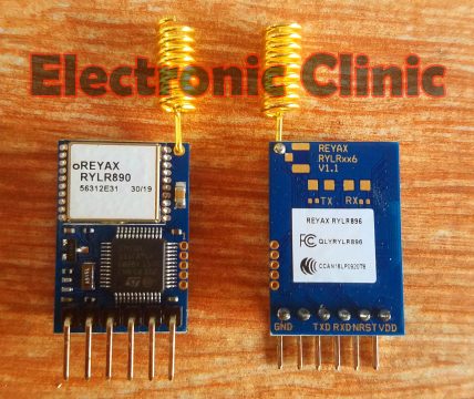
Pinout of the Lora Transceiver Module, RYLR890/RYLR896:
As you can see in the picture above, this transceiver module has a total of 6 pins; which are clearly labeled as VDD, NRST “which is the reset pin active low”. RXD, TXD, pin number 5 is not used, while pin number 6 is the ground.
Multiple Transmitters based on the Lora and Arduino, Circuit Diagram:
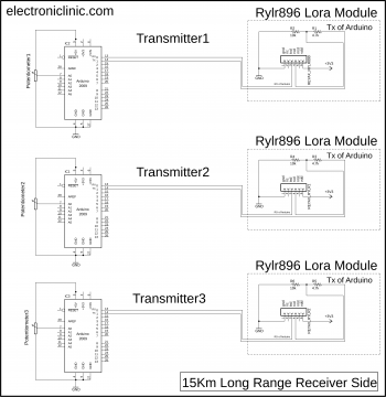
If you’ve ever tried to connect a 3.3V device to a 5V system, you know what a challenge it can be. In the circuit diagram you can see three Lora Transceiver modules are interfaced with three Arduino boards. Lora Transceiver modules can only handle 3.3V voltage levels. If these modules are directly interfaced with the Arduino, then there is a high chance of damaging the Lora modules.
To safely use the Lora modules you have two options, you can use a bi-directional voltage level converter, or you can use a pair resistors. As you can see in the circuit diagram above I used a pair of resistors 10k and 4.7k. The connections of all the three transmitters are exactly the same. You can see a potentiometer is connected with the Analog pin A0.
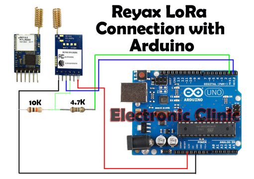
The Lora transceiver module connection with the Arduino Uno or Arduino Nano will remain the same.
Single Receiver based on the Lora and Arduino, Circuit Diagram:
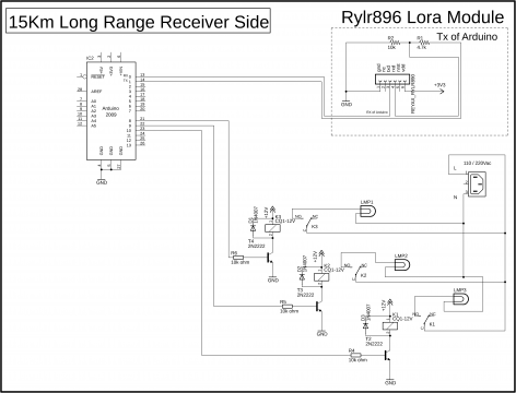
The Lora Transceiver module connection with the Arduino board will remain the same. A three channel relay module is connected with the Arduino using digital pins 8,9, and 10. You can use a readymade 12V 3-channel relay module, or you can follow the connections and build the one by yourself.
Lora Multiple Transmitters Arduino Programming:
As in this project, three transmitters are used so we will need 3 Arduino codes. You can use the same code on all the three Arduino boards but with different headers.
Transmitter 1 Arduino Code:
|
1 2 3 4 5 6 7 8 9 10 11 12 13 14 15 16 17 18 19 20 21 22 23 24 25 26 27 28 29 30 31 32 33 34 35 36 37 38 39 40 41 42 43 |
int vresistor = A0; int vrdata = 0; int data_length; String sensorsdata; void setup() { // put your setup code here, to run once: Serial.begin(115200); pinMode(vresistor,INPUT); } void loop() { // put your main code here, to run repeatedly: MultipleSensors(); send_data(sensorsdata , data_length); delay(100); sensorsdata = ""; } void MultipleSensors() { vrdata = analogRead(vresistor); sensorsdata = sensorsdata + "S1" + "%" + vrdata ; //Serial.println("sensor value:"); //Serial.println(vrdata); // find the length of data data_length = sensorsdata.length(); //Serial.println("data length:"); //Serial.println(data_length); } void send_data(String sensorvalue, int valuelength) { String mymessage; mymessage = mymessage + "AT+SEND=0" + "," + valuelength + "," + sensorvalue + "\r"; Serial.println(mymessage); //Serial.println("AT+SEND=0,6,Hello!\r"); } |
Transmitter 2 Arduino Code:
|
1 2 3 4 5 6 7 8 9 10 11 12 13 14 15 16 17 18 19 20 21 22 23 24 25 26 27 28 29 30 31 32 33 34 35 36 37 38 39 40 41 42 43 |
int vresistor = A0; int vrdata = 0; int data_length; String sensorsdata; void setup() { // put your setup code here, to run once: Serial.begin(115200); pinMode(vresistor,INPUT); } void loop() { // put your main code here, to run repeatedly: MultipleSensors(); send_data(sensorsdata , data_length); delay(100); sensorsdata = ""; } void MultipleSensors() { vrdata = analogRead(vresistor); sensorsdata = sensorsdata + "S2" + "%" + vrdata ; //Serial.println("sensor value:"); //Serial.println(vrdata); // find the length of data data_length = sensorsdata.length(); //Serial.println("data length:"); //Serial.println(data_length); } void send_data(String sensorvalue, int valuelength) { String mymessage; mymessage = mymessage + "AT+SEND=0" + "," + valuelength + "," + sensorvalue + "\r"; Serial.println(mymessage); //Serial.println("AT+SEND=0,6,Hello!\r"); } |
Transmitter 3 Arduino Code:
|
1 2 3 4 5 6 7 8 9 10 11 12 13 14 15 16 17 18 19 20 21 22 23 24 25 26 27 28 29 30 31 32 33 34 35 36 37 38 39 40 41 42 43 |
int vresistor = A0; int vrdata = 0; int data_length; String sensorsdata; void setup() { // put your setup code here, to run once: Serial.begin(115200); pinMode(vresistor,INPUT); } void loop() { // put your main code here, to run repeatedly: MultipleSensors(); send_data(sensorsdata , data_length); delay(100); sensorsdata = ""; } void MultipleSensors() { vrdata = analogRead(vresistor); sensorsdata = sensorsdata + "S3" + "%" + vrdata ; //Serial.println("sensor value:"); //Serial.println(vrdata); // find the length of data data_length = sensorsdata.length(); //Serial.println("data length:"); //Serial.println(data_length); } void send_data(String sensorvalue, int valuelength) { String mymessage; mymessage = mymessage + "AT+SEND=0" + "," + valuelength + "," + sensorvalue + "\r"; Serial.println(mymessage); //Serial.println("AT+SEND=0,6,Hello!\r"); } |
Transmitters Code Explanation:
If you look at the code of all the three transmitters, you will find a change only in the header value, S1, S2, S3. Using S1, S2, and S3, the receiver can know exactly from which transmitter its receiving the data. We simple make a message which consists of the header value S1 or S2 or S3, and the Sensor value separated using % as the delimiter.
Lora Single Receiver Arduino Programming:
|
1 2 3 4 5 6 7 8 9 10 11 12 13 14 15 16 17 18 19 20 21 22 23 24 25 26 27 28 29 30 31 32 33 34 35 36 37 38 39 40 41 42 43 44 45 46 47 48 49 50 51 52 53 54 55 56 57 58 59 60 61 62 63 64 65 66 67 68 69 70 71 72 73 74 75 76 77 78 79 80 81 82 83 84 85 86 87 88 89 90 91 92 93 94 95 96 97 98 99 100 101 102 103 104 105 106 107 108 109 110 111 112 113 114 115 116 117 118 119 120 121 122 123 124 125 126 127 128 129 130 131 132 133 134 135 136 137 138 139 |
String myString; String garbage; char data; int Sensor1; int Sensor2; int Sensor3; int Relay1 = 8; int Relay2 = 9; int Relay3 = 10; void setup() { // put your setup code here, to run once: Serial.begin(115200); Serial.print("AT\r\n"); delay(100); pinMode(Relay1, OUTPUT); pinMode(Relay2, OUTPUT); pinMode(Relay3, OUTPUT); // by default keep all relays low digitalWrite(Relay1, LOW); digitalWrite(Relay2, LOW); digitalWrite(Relay3, LOW); } void loop() { // put your main code here, to run repeatedly: if ( Serial.available() > 0 ) { garbage = Serial.readString(); // consists of the +ERR=2 ERROR. myString = Serial.readString(); Serial.println(myString); //Serial.println("Garbage:"); //Serial.println(garbage); String l = getValue(myString, ',', 0); // address String m = getValue(myString, ',', 1); // data length String n = getValue(myString, ',', 2); // data String o = getValue(myString, ',', 3); //RSSI String p = getValue(myString, ',', 4); //SNR // now i am going to split the data string n which consists of the Sensors values // in this string sensors values are separated by the % sign. String q = getValue(n, '%', 0); // Header String r = getValue(n, '%', 1); // sensor values from multiple transmitters if ( ( q != "") && ( r != "" )) { Serial.println("Sensor:"); Serial.println(q); Serial.println("data:"); Serial.println(r); if ( q == "S1") { Sensor1 = r.toInt(); } if ( q == "S2") { Sensor2 = r.toInt(); } if ( q == "S3") { Sensor3 = r.toInt(); } myString = ""; } Serial.println("Sensor1"); Serial.println(Sensor1); Serial.println("Sensor2"); Serial.println(Sensor2); Serial.println("Sensor3"); Serial.println(Sensor3); if ( Sensor1 <= 200 ) { digitalWrite(Relay1, HIGH); Serial.println("Relay1 High"); } if ( Sensor1 > 200 ) { digitalWrite(Relay1, LOW); Serial.println("Relay1 Low"); } if ( Sensor2 <= 200 ) { digitalWrite(Relay2, HIGH); } if ( Sensor2 > 200 ) { digitalWrite(Relay2, LOW); } if ( Sensor3 <= 200 ) { digitalWrite(Relay3, HIGH); } if ( Sensor3 > 200 ) { digitalWrite(Relay3, LOW); } } } String getValue(String data, char separator, int index) { int found = 0; int strIndex[] = { 0, -1 }; int maxIndex = data.length() - 1; for (int i = 0; i <= maxIndex && found <= index; i++) { if (data.charAt(i) == separator || i == maxIndex) { found++; strIndex[0] = strIndex[1] + 1; strIndex[1] = (i == maxIndex) ? i+1 : i; } } return found > index ? data.substring(strIndex[0], strIndex[1]) : ""; } |
Receiver Code Explanation:
String myString;
String garbage;
char data;
I defined three variables Sensor1, Sensor2, and Sensor3. These variables will be used to store the values of potentiometers coming from the transmitters.
int Sensor1;
int Sensor2;
int Sensor3;
then I defined pins for the 3 relays connected with pins 8, 9, and 10.
int Relay1 = 8;
int Relay2 = 9;
int Relay3 = 10;
void setup() {
// put your setup code here, to run once:
Serial.begin(115200); // activated the serial communication, and selected 115200 as the Baud Rate.
Serial.print(“AT\r\n”);
delay(100);
relays are the output devices
pinMode(Relay1, OUTPUT);
pinMode(Relay2, OUTPUT);
pinMode(Relay3, OUTPUT);
// by default keep all relays low
digitalWrite(Relay1, LOW);
digitalWrite(Relay2, LOW);
digitalWrite(Relay3, LOW);
}
void loop() {
// put your main code here, to run repeatedly:
We use the if condition to check if the Arduino board has received any data from the Lora.
if ( Serial.available() > 0 )
{
garbage = Serial.readString(); // consists of the +ERR=2 ERROR.
Read the string.
myString = Serial.readString();
print the string for debugging purposes, to check if we have received the data. Later you can comment this line of code.
Serial.println(myString);
//Serial.println(“Garbage:”);
//Serial.println(garbage);
String l = getValue(myString, ‘,’, 0); // address
String m = getValue(myString, ‘,’, 1); // data length
String n = getValue(myString, ‘,’, 2); // data
String o = getValue(myString, ‘,’, 3); //RSSI
String p = getValue(myString, ‘,’, 4); //SNR
// now i am going to split the data string n which consists of the Sensors values
// in this string sensors values are separated by the % sign.
String q = getValue(n, ‘%’, 0); // Header
String r = getValue(n, ‘%’, 1); // sensor values from multiple transmitters
if ( ( q != “”) && ( r != “” ))
{
Serial.println(“Sensor:”);
Serial.println(q);
Serial.println(“data:”);
Serial.println(r);
From here we start checking, if the sensor values is received from the Transmitter1, Transmitter2, or from the Transmitter3. We check this by using the if conditions. if q has the string S1 it means the data is received from the Transmitter1. So the value stored in r is converter to integer and then stored in Sensor1. In the same way, we do it for the remaining sensors.
if ( q == “S1”)
{
Sensor1 = r.toInt();
}
if ( q == “S2”)
{
Sensor2 = r.toInt();
}
if ( q == “S3”)
{
Sensor3 = r.toInt();
}
myString = “”;
}
Serial.println(“Sensor1”);
Serial.println(Sensor1);
Serial.println(“Sensor2”);
Serial.println(Sensor2);
Serial.println(“Sensor3”);
Serial.println(Sensor3);
if ( Sensor1 <= 200 )
{
digitalWrite(Relay1, HIGH);
Serial.println(“Relay1 High”);
}
if ( Sensor1 > 200 )
{
digitalWrite(Relay1, LOW);
Serial.println(“Relay1 Low”);
}
Finally, we use these if conditions to control all the three relays. I don’t think so you need any explanation for the code given below.
if ( Sensor2 <= 200 )
{
digitalWrite(Relay2, HIGH);
}
if ( Sensor2 > 200 )
{
digitalWrite(Relay2, LOW);
}
if ( Sensor3 <= 200 )
{
digitalWrite(Relay3, HIGH);
}
if ( Sensor3 > 200 )
{
digitalWrite(Relay3, LOW);
}
}
}
String getValue(String data, char separator, int index)
{
int found = 0;
int strIndex[] = { 0, -1 };
int maxIndex = data.length() – 1;
for (int i = 0; i <= maxIndex && found <= index; i++) {
if (data.charAt(i) == separator || i == maxIndex) {
found++;
strIndex[0] = strIndex[1] + 1;
strIndex[1] = (i == maxIndex) ? i+1 : i;
}
}
return found > index ? data.substring(strIndex[0], strIndex[1]) : “”;
}
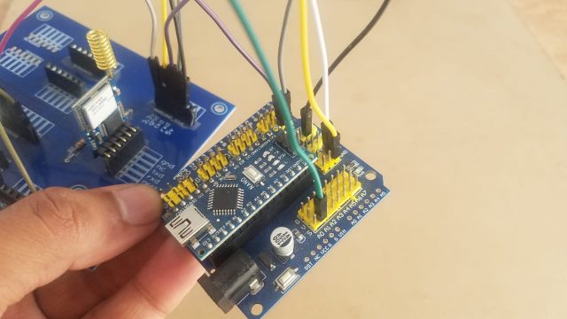
I did similar connections for all the transmitters and the receiver module. On the transmitter sides I connected the potentiometers, while on the receiver sides I connected the relays.
Finally, you can use the potentiometers to control all the three relays from three different locations.
You can easily modify this project; you can add multiple sensors with each transmitter. This way so many amazing projects can be designed. I hope you have learnt something new from this article. For video tutorials visit my YouTube Channel “Electronic Clinic”.
Discover more from Electronic Clinic
Subscribe to get the latest posts sent to your email.


Is Transmission prortocol is already implemented ?
i mean what if two signal collide