Raspberry Pi LCD 16×2 Liquid Crystal display interfacing and python code
Table of Contents
Raspberry Pi LCD 16×2, Overview:
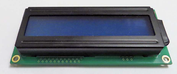
Raspberry Pi LCD 16×2 Liquid Crystal Display interfacing and Python Code– The 16X2 LCD display is a very inexpensive module (see Figure 1). It usually has a backlight and can be easily powered up using the Raspberry Pi 5V. It is ideal for installation in Plastic or wooden boxes and are used to display selected data. The data can be anything, it may be the Temperature, the Humidity, Motor Speed, a Text message, Numeric Data, etc.

Amazon Purchase Links:
Wireless Keyboard and Mouse for raspberry pi:
Night vision Camera for Raspberry Pi:
Oled HDMI touch display for raspberry pi:
Other Tools and Components:
Super Starter kit for Beginners
PCB small portable drill machines
*Please Note: These are affiliate links. I may make a commission if you buy the components through these links. I would appreciate your support in this way!
When purchasing a 16×2 LCD module, ensure that it is an HD44780 controller or a compatible controller is installed. The HD44780 is the Display controller built into the module, which displays the commands of the Raspberry Pi in characters implemented on the display. The Amazon purchase link is already given above. You can also find quite a few under the keyword HD44780 further sources of supply on the Internet.
16X2 LCD Pin assignment:
The LCD module has 16 connection pins. Depending on the version, it already has a pin header. The pin assignment reads as follows:
- Pin 1: GND (VSS)
- Pin 2: PVCC 5 V (VCC)
- Pin 3: Contrast (V0)
- Pin 4: Register Select (RS)
- Pin 5: Read / Write (R / W)
- Pin 6: Enable (E)
- Pin 7: Bit 0 – not required (DB0)
- Pin 8: Bit 1 – not required (DB1)
- Pin 9: Bit 2 – not required (DB2)
- Pin 10: Bit 3 – not required (DB3)
- Pin 11: Bit 4 (DB4)
- Pin 12: Bit 5 (DB5)
- Pin 13: Bit 6 (DB6)
- Pin 14: Bit 7 (DB7)
- Pin 15: Backlight anode (LED +)
- Pin 16: backlight cathode (LED)
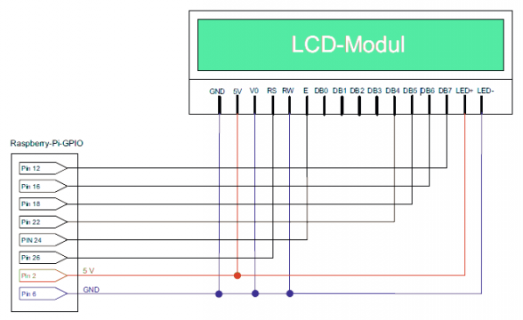
The connection to the Raspberry Pi requires a total of six free GPIO pins plus 5V and GND. Connect the display as shown in the circuit diagram (see Figure 2).
In the circuit diagram, the connection for setting the contrast of the display is to ground. Alternatively, you can switch a potentiometer in front of this connection to adjust the contrast of the 16×2 LCD display. With our method, the display has always full contrast and is ideal to read.

Raspberry Pi 16×2 LCD Programming:
We use a Python library from Adafruit to control the display. This is perfectly tailored to the display and contains all the useful functions that are necessary for the operation of the display. First, load the source code of the Adafruit Python library onto the Raspberry
Pi:
git clone \
git: // github. com / adafruit / Adafruit – Raspberry -Pi – Python – Code.git
If you get the message that the git command is unknown, you have to do this First install the command:
sudo apt – get install git
Now switch to the Adafruit-Raspberry-Pi-Python-Code folder on the Raspberry Pi, or use a file manager such as WinSCP for Windows or Cyberduck for Mac OS to browse the folder. You can find some Python here Libraries and drivers from Adafruit for many popular extensions to the Raspberry Pi. The Adafruit_CharLCD folder is relevant for this section. You need the Adafruit_CharLCD.py file. Copy this file into the folder where you saved your save future Python script.
The Adafruit script must be adapted to the GPIO pins you are using. This is done quickly. Open the Adafruit_CharLCD.py file with an editor, and look for the following instruction, which is about two here for space reasons Lines was distributed:
def init (self, pin_rs = 25, pin_e = 24,
pins_db = [23, 17, 21, 22], GPIO = None):
If you want to use the GPIO pins as described in this chapter, then change the line as follows:
def init (self, pin_rs = 7, pin_e = 8,
pins_db = [25, 24, 23, 18], GPIO = None):
Note that the pins are indicated in the BCM designation. That is, pin 26 corresponds to BCM 7 etc. The parameters have the following meaning:
- pin_rs: corresponds to Register Select (RS).
- pin_e: corresponds to Enable (E).
- pins_db = [. . . ]: controls (from left to right) bit 4 to bit 7.
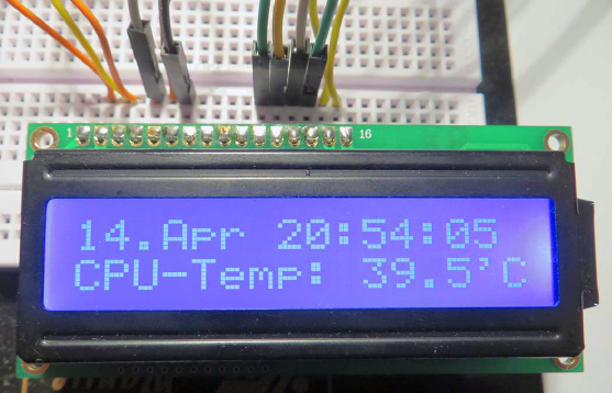
You can freely choose the pins and only have to adjust the row accordingly. After that, start writing your software. Demonstrate as always we show you how to use the display using a Python script. in the following code will show the current date and the CPU temperature in the display and updated every five seconds. As the Adafruit Libraries so far have not yet been optimized for Python 3, we use Python 2.
|
1 2 3 4 5 6 7 8 9 10 11 12 |
#! / usr / bin / python from Adafruit_CharLCD import Adafruit_CharLCD import time import commands lcd = Adafruit_CharLCD () lcd.begin (16, 2) while True: time = time.strftime ("% y.% b% H:% M:% S") temp = commands.getoutput ("/ opt / vc / bin / vcgencmd measure_temp") lcd.message ("% s \ nCPU - Temp:% s1f"% (time, temp [5:])) time.sleep (5) lcd.home () |
The first line imports the Adafruit library previously downloaded. The function lcd.message () shows the transmitted values as characters on the display. If the transmitted text contains the newline string \ n, a line break will be found there in the second line of the display. Note that each line can have a maximum of 16 characters. If a line contains more characters, these are cut off. As in the 16×2 LCD, 16 means columns and 2 means rows.

lcd.home () sets the display cursor back to the beginning so that the entire Content of the LCD module is overwritten every five seconds. The shell command for the temperature output returns the temperature as temp = 35 ° C. For our ad However, we first need the numerical value after the fifth character, i.e. after the sign =.Temp [5:] does this in the program code.
Table 1: Important “lcd” functions
| function | Meaning |
| lcd.clear() | Empties the entire display. |
| lcd.setCursor (column, row) | Places the cursor at the defined position. |
| lcd.noDisplay () | Turns off the display. |
| lcd.display () | Switches the display back on. |
| lcd.scrollDisplayLeft () | Scrolls the text one line to the left. |
| lcd.scrollDisplayRight () | Scrolls the text one line to the right. |
In the file Adafruit_CharLCD.py various other functions for display Control included (see table 1). The functions scrollDisplayLeft and scrollDisplayRight require special handling in Python. So that you can e.g. can display text with more than 16 characters in one line as ticker, use a for loop:
|
1 2 3 4 5 6 7 8 9 |
text = ("Much too long text for one line") lcd. message (text) for i in range (len (text) - 16): lcd.scrollDisplayLeft () time. sleep (0.5) |
Note:
Save GPIO lines:
So-called I2C adapters are available for common 16 x 2-LC displays. It is about to boards onto which the display can be attached. The connection to the Raspberry Pi then only takes place via the I2C lines. So keep yourself access to the otherwise occupied GPIO pins.
