RFID Chip in Hand, Talking RFID System using Arduino, chip implant uses
Last Updated on August 17, 2024 by Engr. Shahzada Fahad
Table of Contents
RFID Chip in Hand, Description:
RFID Chip in Hand, Talking RFID System using Arduino, chip implant uses- This week we will be showing you an interesting system a friend of mine has made. A talking RFID bike control system that works with the RFID Chip in Hand. Before we are going to explain anything, first, take a look at the video given at the end of this article to get the idea of what you are going to learn after reading this article.
About the Sponsor of this Project, PCBWay:

High quality & Only 24 Hours Build time
The PCB board used in designing the talking RFID System is sponsored by PCBWay. Feel free to visit their website PCBWay.com to not only find out what awesome PCB and Assembly services they offer but also to easily upload your Gerber files and thus order affordable and high quality PCBs quickly. The sign up process hardly takes 1 minute and you are welcomed with a 5 dollars welcome bonus.
Download Project Gerber Files:
A talking RFID System. This allows the user the ability to interact with any system that uses the RFID or NFC technology. You can use your hand as the key or you can use a regular RFID keychain or even you can use an RFID tag. So, in the end you are the one to decide, whether to get the RFID Chip in Hand.
In this article, we will cover,
- How to get the RFID chip Hand Implant.
- Complete circuit diagram explanation.
- Components explanation.
- We will talk about the PCB Gerber files.
- How to place online order.
- Program explanation.
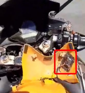
Our designed talking RFID system can be used with Bikes, Door Lock Systems, Home Automation systems, etc.
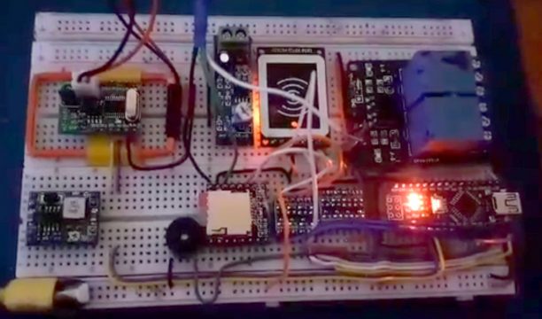
Making the final Talking RFID system wasn’t that easy, we had to perform a series of experiments on breadboards, we used different types of MP3 players and RFID modules.
These experiments helped us in selecting the final components to make a complete working product.
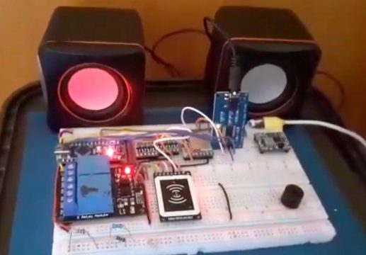
We have been testing the final prototype model for days, it had some bugs which we fixed and now it’s working great.
Finally, we were able to design a complete working product. Now, let’s talk about the components, connections, and programming.
Without any further delay, let’s get started!!!
Purchase links:
Arduino Nano USB-C Type (Recommended)
NExT RFID Chip Implant US based
*Disclosure: These are affiliate links. As an Amazon Associate I earn from qualifying purchases.
Getting the RFID implant:

In my previous article “How to get RFID Chip Implant in Humans and practical uses with Arduino”, I have already explained each and every detail, like for example, the type of the RFID chip we selected, its technical specs, how to get these RFID chips, etc. so I highly recommend you should take a look.
We also designed a very basic Bike access control system with sound acknowledgement. In this project we used the DFplayer Mini Mp3 module. The above two articles worth reading, you will get answers to a lot of questions.
Bi-directional Voltage Level Converter:
If you’ve ever tried to connect a 3.3V device to a 5V system, you know what a challenge it can be. bi-directional logic level converter is a small device that safely steps down 5V signals to 3.3V AND steps up 3.3V to 5V at the same time. This level converter also works with 2.8V and 1.8V devices.

The level converter is very easy to use. The board needs to be powered from the two voltage sources (high voltage and low voltage) that your system is using. High voltage (5V for example) to the ‘HV’ pin, low voltage (3.3V for example) to ‘LV’, and ground from the system to the ‘GND’ pin.
YX5200 or 5300 Mini MP3 Player:
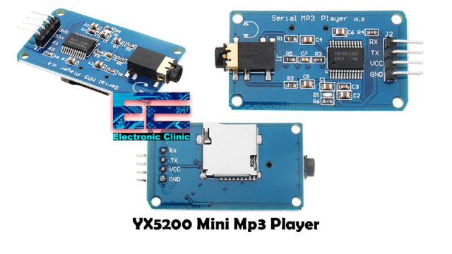
This is the YX5200 or 5300 Mini MP3 Player provided with an audio jack and 4 male headers on the top side, while a slot for the SD card can be found on the back side. The 4 male headers are labeled as RX, TX, VCC, and GND. This mini mp3 module can be easily powered up using the Arduino 3.3v or 5 volts. Using the RX and TX pins commands can be sent serially from the Arduino board to this MP3 player. This mp3 module can also be easily used with the Nodemcu ESP8266 and also with the ESP32 Wifi + Bluetooth module.
YX5200 Details:
- Support sampling frequency (KHz):8 / 11.025 / 12 / 16 / 22.05 / 24 / 32 / 44.1 / 48
- Support file format: MP3/WAV
- Support Micro SD card, Micro SDHC Card
- 30 class adjustable volume
- UART TTL serial control playback mode, baud rate is 9600bps
- Power supply can be 3.2 ~ 5.2VDC
TDA7297 Audio Amplifier:
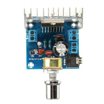
This is the TDA7297 digital Audio Amplifier module provided with the Audio jack, Volume adjustment knob, two block terminals on the left and right sides for connecting the speakers, and one terminal block for connecting the 12V power supply.
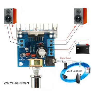
This is the basic connection diagram. This Audio amplifier module can be connected with the YX5200 Mini Mp3 module through an AUX cable.

Using the same connections we started checking the TDA7297 Audio Amplifier. We connected the TDA7297 Audio Amplifier with the Mini Mp3 player using the Aux cable and we were able to play the audio files.
Mini MFRC522 RFID Reader:
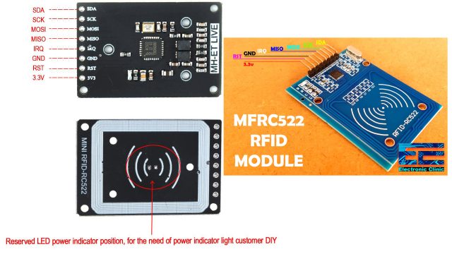
The mini RC522 RFID Reader which is just like the bigger version, you can clearly see in the picture it has got the same pins. The only difference is in the size and this is the only reason we selected this module. For the best and long term performance we are going to connect all the pins of the Mini MFRC522 RFID module with the Arduino Nano through the Bi-directional Voltage level converter.
Interfacing Mini MFRC522 and YX5200 Mini MP3 Player with Arduino Nano, Circuit Diagram:
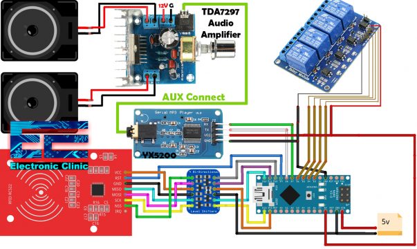
This schematic clearly shows the connections of Mini MFRC522 RFID Module, Bi-directional Voltage level converter, YX5200 Mini Mp3 player, 5V 4 channel relay module, and TDA7279 Audio amplifier with Arduino Nano.
Let’s start with the 5V 4-channel relay module. The Arduino Nano D3 to D6 pins are connected with the 4-channel relay module to control the 4 relays. The 5V and GND wires from the Arduino Nano are also connected with the VCC and GND pins of the relay module.
D7 and D8 pins of the Arduino Nano are connected with the RX and TX pins of the YX5200 Mini Mp3 module. The VCC and GND pins of the Mp3 module are connected with the Arduino Nano 5V and GND pins. The YX5200 Mini Mp3 module is then connected with the TDA7297 Audio amplifier through the Aux cable. The TDA7297 Audio amplifier 12V and GND terminals are connected with the 12V Battery. While the other block terminals are connected with the speakers.
The Mini MFRC522 RFID reader module is connected with the Arduino Nano through a Bi-directional voltage level converter using the Arduino Nano pins D9, D10, D11, D12, and D13. While the VCC of the Mini MFRC522 is connected with the 3.3v and of course the GND is connected with the ground of the Arduino Nano.
Talking RFID system PCB board:
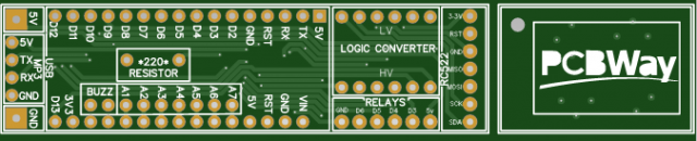
Next, we designed the PCB using the EasyEDA PCB designing tool and generated the Gerber Files. Then I used the PCBWay online Gerber viewer and double checked all the connections. After I was satisfied, the final step was to upload the Gerber files.
PCBWay Online Order placement:
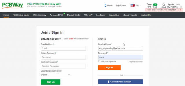
You can simply start by typing PCBWay.com.
Click on the Sign in.
The sign up process hardly takes 1 minute. You can sign up using your email id or your Facebook account. If you are new, then you will also get a 5 dollars welcome bonus. Anyhow I have already signed up, so I will go ahead and click on the Sign In button.
Once Signed In, click on the PCB instant quote, this will take you to another page. Scroll down and enter the desired information.
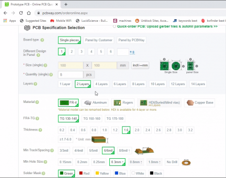
- PCB size, I entered 100×100 mm. As I am ordering a PCB panel board.
- Quantity, I selected 5 pieces.
- Solder Mask, the default is Green, but I selected the Black color.
- You can select white or black color silkscreen. I will leave everything else to their default values.
- Finally, click on the calculate button.
- Select your country and the service.
- Finally, click on the Save to Cart button.
- The final step is to add the Gerber files, for this click on the Add Gerber File button and select the folder.

- Click on the Submit Order now button.
Once the order is submitted, the PCBWay staff members will review the Gerber files. When the Gerber files are approved they will let you know through an email.
Talking RFID Bike control system Arduino Programming:
Below is the final code of the talking RFID Bike control system. Most of the instructions are well commented.
|
1 2 3 4 5 6 7 8 9 10 11 12 13 14 15 16 17 18 19 20 21 22 23 24 25 26 27 28 29 30 31 32 33 34 35 36 37 38 39 40 41 42 43 44 45 46 47 48 49 50 51 52 53 54 55 56 57 58 59 60 61 62 63 64 65 66 67 68 69 70 71 72 73 74 75 76 77 78 79 80 81 82 83 84 85 86 87 88 89 90 91 92 93 94 95 96 97 98 99 100 101 102 103 104 105 106 107 108 109 110 111 112 113 114 115 116 117 118 119 120 121 122 123 124 125 126 127 128 129 130 131 132 133 134 135 136 137 138 139 140 141 142 143 144 145 146 147 148 149 150 151 152 153 154 155 156 157 158 159 160 161 162 |
/* Download Libraries: https://www.electroniclinic.com/arduino-libraries-download-and-projects-they-are-used-in-project-codes/ */ #include "Arduino.h" #include "SoftwareSerial.h" #include "DFRobotDFPlayerMini.h" #include <SPI.h> #include <MFRC522.h> SoftwareSerial mySoftwareSerial(8, 7); // RX, TX DFRobotDFPlayerMini myDFPlayer; void printDetail(uint8_t type, int value); #define SS_PIN 10 // The SS pin is connected to Pin 10 #define RST_PIN 9 // the RST pin is conected tp pin 9 MFRC522 mfrc522(SS_PIN, RST_PIN); // Create MFRC522 instance. int relay1 = 6; // relay 1 dash int relay2 = 5; // relay 2 ignition int relay3 = 4; //relay 3 for mp3 player pops int relay4 = 3; //relay 4 NC int ledbuz = 2;// buzzer or led void setup() { pinMode(7, OUTPUT); // Declaring this Relay as output digitalWrite(7, HIGH); // setting it to OFF pinMode(relay1, OUTPUT); // Declaring this Relay as output digitalWrite(relay1, HIGH); // setting it to OFF pinMode(relay2, OUTPUT); //Declaring this Relay as output digitalWrite(relay2, HIGH); // setting it to OFF #if defined(usingledbuz) pinMode(ledbuz, OUTPUT); //Declaring the buzzer or LED as output digitalWrite(ledbuz, LOW); // setting it to OFF #endif #if defined(usingmp3player) mySoftwareSerial.begin(9600); #endif Serial.begin(115200); // Initiate a serial communication #if defined(usingmp3player) Serial.println(); Serial.println(F("")); if (!myDFPlayer.begin(mySoftwareSerial)) { //Use softwareSerial to communicate with mp3. Serial.println(F("Unable to begin:")); Serial.println(F("1.Please recheck the connection!")); Serial.println(F("2.Please insert the SD card!")); while(true){ delay(0); // Code to compatible with ESP8266 watch dog. } } Serial.println(F("mp3Player ready.")); //myDFPlayer.volume(28); //Set volume value. From 0 to 30 myDFPlayer.play(2); //Play the first mp3 #endif #if defined(usingrc522) SPI.begin(); // Initiate SPI bus mfrc522.PCD_Init(); // Initiate MFRC522 //If you set Antenna Gain to Max it will increase reading distance //mfrc522.PCD_SetAntennaGain(mfrc522.RxGain_max); Serial.println("Approximate your UID to the reader..."); Serial.println(); #endif #if defined(usinghz1051) wg.begin(); #endif #if defined(usingledbuz) digitalWrite(ledbuz, HIGH);//activates led or buzzer , one beep delay(200);// digitalWrite(ledbuz, LOW); #endif } void loop() { #if defined(usingrc522) // Awaiting an UID to be Presented if ( ! mfrc522.PICC_IsNewCardPresent()) { return; } // Select one of the cards if ( ! mfrc522.PICC_ReadCardSerial()) { return; } //Display UID on serial monitor Serial.print("UID tag :"); String content= ""; byte letter; for (byte i = 0; i < mfrc522.uid.size; i++) { Serial.print(mfrc522.uid.uidByte[i] < 0x10 ? " 0" : " "); Serial.print(mfrc522.uid.uidByte[i], HEX); content.concat(String(mfrc522.uid.uidByte[i] < 0x10 ? " 0" : " ")); content.concat(String(mfrc522.uid.uidByte[i], HEX)); } Serial.println(); Serial.print("Message : "); content.toUpperCase(); if (content.substring(1) == (hfuid1)|| content.substring(1)== (hfuid2)) //change here the UID of the cards to give access, add more with || content.substring(1)== "another UID" {correctuid();} else {wronguid();} } #endif void correctuid(){ // If UID is correct do this .... Serial.println("Authorized access Motorcycle Engaged"); digitalWrite(relay1, LOW); //activates bike, lights up Dash Serial.println("Motorcycle Engaged"); #if defined(usingledbuz) digitalWrite(ledbuz, HIGH);//activates led or buzzer , one beep delay(200);// digitalWrite(ledbuz, LOW); // #endif #if defined (usingmp3player) myDFPlayer.play(3); //Play the first mp3 #endif delay(2500);//allows bike time to start up digitalWrite(relay2, LOW);//activates ignition Serial.println("Motorcycle Starting"); delay(2500);//waits 4 seconds for bike to tick over digitalWrite(relay2, HIGH); //deactivates ignition. Serial.println("Deactivate Ignition"); } void wronguid (){ // if uid incorrect do this.... Serial.println(" Access denied"); #if defined (usingmp3player) myDFPlayer.play(1); //Play the first mp3 #endif #if defined(usingledbuz) digitalWrite(ledbuz, HIGH);//activates led or buzzer , one beep delay(100); digitalWrite(ledbuz, LOW); //deactivates ignition. delay(100); digitalWrite(ledbuz, HIGH);//activates led or buzzer , one beep delay(200);// digitalWrite(ledbuz, LOW); #endif delay(3000); } // ------------------------------------------------- // Code End // ------------------------------------------------- |
Talking RFID Bike control system Final Testing:
We developed a prototype model, and it’s been under test for several days. You already saw everything in action. Now we are waiting for the final PCBs from the PCBWay Company to complete our final product. Meanwhile we will continue with the performance tests and will keep you updated.
After receiving the PCBs I will update this article, add new images of the final product, and will also explain the entire assembly and installation. Don’t forget to subscribe to my website and YouTube channel, if you want to be notified.
Watch Video Tutorial:
Discover more from Electronic Clinic
Subscribe to get the latest posts sent to your email.


Hello can i get mp3 sounds files?