Servo Motor Arduino, Joystick servo motor control
Last Updated on September 21, 2024 by Engr. Shahzada Fahad
Table of Contents
Servo Motor Arduino:
Servo Motor Arduino- In this article, you are going to learn how to control Servo Motors using Arduino and a 2-axis Analog Joystick. It’s a complete guide for beginners explaining how to wire up the Joystick and different servos and how to take care of the power supply needs. In this tutorial, we will using a micro servo motor, 10Kg torque servo motor, and a 25Kg torque servo motor. I also have a detailed article on how to control multiple servos at the same time using an Ultrasonic Sensor.
Amazon Links:
Arduino Nano USB-C Type (Recommended)
*Disclosure: These are affiliate links. As an Amazon Associate I earn from qualifying purchases.
MG996R Servo:
MG996R Metal Gear Micro Servo Motor with a maximum torque of 11 kg/cm rotates from 0 to 180 degree based on the duty cycle of the PWM. The MG996R is a metal gear servo motor with a maximum stall torque of 11 kg/cm. Like other RC servos the motor rotates from 0 to 180 degree based on the duty cycle of the PWM wave supplied to its signal pin.

| Wire Number | Wire Colour | Description |
| 1 | Brown | Ground wire connected to the ground of system |
| 2 | Red | Powers the motor typically +5V is used |
| 3 | Yellow | PWM signal is given in through this wire to drive the motor |
Specification:
- Operating Voltage is +5V typically
- Current: 2.5A (6V)
- Stall Torque: 9.4 kg/cm (at 4.8V)
- Maximum Stall Torque: 11 kg/cm (6V)
- Operating speed is 0.17 s/60°
- Gear Type: Metal
- Rotation : 0°- 180°
- Weight of motor : 55gm
- Package includes gear horns and screws
Analog Joystick:

This is a JoyStick Module PS2 Breakout Sensor very similar to the ‘analog’ joysticks on PS2 (PlayStation 2) controllers. Directional movements are simply two potentiometers – one for each axis. Pots are ~10k each. This joystick also has a select button that is actuated when the joystick is press down. With the help of this Joystick Module, you can measure position coordinates on the X and Y axis by moving the “hat”. It also contains a switch that is press-able by pushing the “hat”.It also contains a switch that is press-able by pushing the “hat” down. Similar to the XBOX controller.
The X and Y axes are two 10k potentiometers which control 2D movement by generating analog signals. When the module is in working mode, it will output two analog values, representing two directions. This module uses the 5V power supply, and value, when reading through analog input, would be about 2.5V, a value will increase with joystick movement and will go up till maximum 5V; the value will decrease when the joystick is moved in other direction till 0V.

Pins:
GND: Ground (0V)
Vcc: Power (+5V)
VRx: X-axis potentiometer.
VRy: Y-axis potentiometer.
SW: Push-button.
Specification:
- Operating Voltage: 5V.
- Dimensions: 40 x 27 x 15 (LxWxH) mm
- Weight: 10gm (without Hat).
- Interface: 2.54mm pin interface leads
- Long service life and stable performance
- Cross rocker as a two-way 10K resistor, with the rocker in a different direction.
Servo Motor Arduino Circuit Diagram:
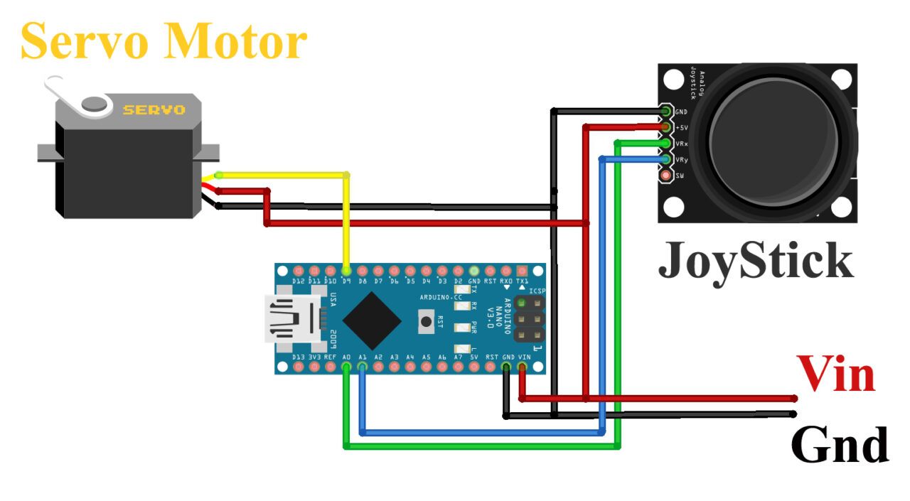
These connections are same for all the Servo motors except the power supply.
- Connect the VCC pin of the JoyStick with Vin of the Arduino nano
- Connect the Ground pin of the JoyStick with Ground pin of the Arduino nano
- Connect the Vrx pin of the JoyStick with A0 pin of the Arduino nano
- Connect the Vry pin of the JoyStick with A1 pin of the Arduino nano
- Connect the signal wire of the Servo motor with D9 pin of the Arduino nano
- Connect the VCC pin of the Servo motor with Vin pin of the Arduino nano
- Connect the Ground pin of the Servo motor with Ground pin of the Arduino nano
If you are using a Micro Servo motor then there is no need to connect an external 5V power supply. You can simply use the Arduino Uno or Arduino Nano onboard power supply to power up the Servo. But if in case you are planning on using large Servo Motors then you will need to connect the Vin and GND pins of the Arduino to the external 5V power supply.

On my designed Arduino development board I have added the 5V and 3A power supply. But if it’s hard for you to make this development board then you can follow the circuit diagram given below.

Servo Motor Arduino Programming:
|
1 2 3 4 5 6 7 8 9 10 11 12 13 14 15 16 17 18 19 20 21 22 23 24 25 26 27 28 29 30 31 32 33 34 35 36 37 38 |
#include <Servo.h> // include servo library Servo servo; // create servo object to control the ESC intservoangle; intjoyX = A0; intjoyY = A1; intjoyVal; // create variable for joystick value void setup() { Serial.begin(9600); servo.attach(9); } void loop() { intjoyValy = analogRead(joyY); // read value from joystick Serial.println(joyValy ); if ((joyValy>= 0) && (joyValy<= 545)) { servoangle = map(joyValy, 0, 545, 0,90); servo.write(servoangle); delay(10); } else if ((joyValy>545) && (joyValy<= 560)) { servo.write(90); delay(10); } else if ((joyValy> 560) && (joyValy<= 1023)) { servoangle= map(joyValy, 560, 1023, 90, 180); servo.write(servoangle); delay(10); } } |
Practical Demonstration:
I was able to control all the three Servo Motors.
Joystick + Micro Servo Motor:
As I said earlier, you can power up the Micro Servo Motors using the Arduino onboard 5V power supply. But if you are using multiple of these servos then use an external power supply.

Joystick + 10Kg Torque Servo Motor:
For 10Kg and High Torque Servos use an external power supply as I explained.

Joystick + 25Kg Servo Motor:

Watch Video Tutorial:
Discover more from Electronic Clinic
Subscribe to get the latest posts sent to your email.


