Voice Recognition Module with Arduino
Last Updated on August 16, 2024 by Engr. Shahzada Fahad
Table of Contents
Voice Recognition Module Description:
Voice Recognition Module with Arduino- This is the DFRobot’s Gravity Offline Language learning voice recognition sensor module; which is so far the best offline voice recognition module I have ever used. I am saying this after testing this remarkable piece of hardware. So, before I am going to explain anything like its features and specifications; allow me to demonstrate its functionality, and then you can decide for yourself whether it’s worth using.
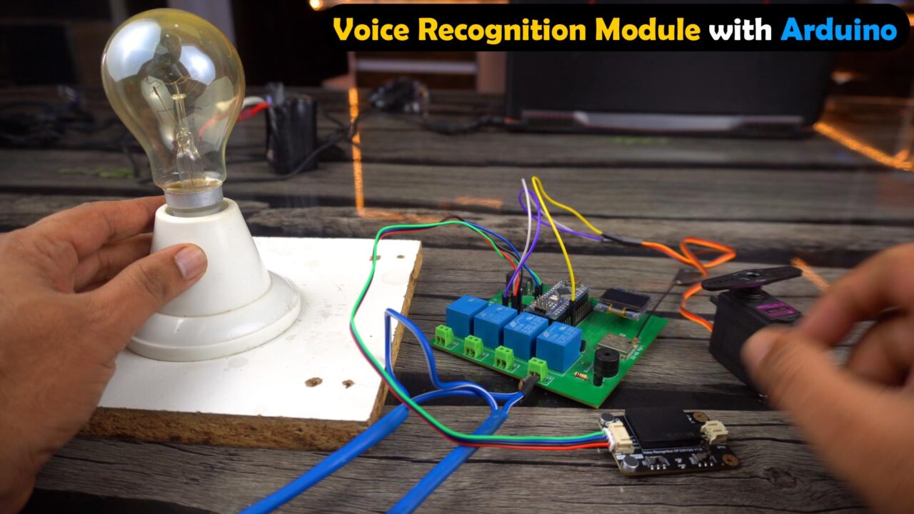
I have connected the Gravity offline voice recognition module to the Arduino Nano; but instead of using the Arduino Nano, you can also use the Arduino Uno, and Arduino Mega. You can also use it with Raspberry pi and ESP32 etc; because this voice recognition module is compatible with 3.3V and 5V controller boards.
Anyway, as usual, I am using my designed Arduino LoRa development board because it already has most of the electronics components like Relays, Oled display module, a 5V buzzer, and a powerful 5V and 3A regulated power supply.
Anyways, for the demonstration purposes; I have connected a 10Kg torque Servo motor, a 110/220Vac bulb, and this board already has a 5V buzzer. So, we are going to control all these loads using built-in voice commands and using custom voice commands.
Let me also tell you, if you are planning on using similar high torque servo motors or GSM modules that draw more current then I highly recommend use an external 5V and 3A power supply, the same 5V and 3A power supply I have added on my Arduino LoRa development board; so I don’t need to use an external 5V power supply. I can use any power source between 9 and 28 volts.
By the way, it’s not compulsory to use these kinds of loads, you can start with Leds, and once you learn how to use built-in voice commands, how to record custom voice commands, and how to use them; then you can control pretty much anything. And this is what I am going to demonstrate right now. So, let’s go ahead and power up the Arduino board.

The voice recognition module has two Leds the Red(PWR) and Blue(ASR). The Red color LED is the Power indicator and the Blue color LED is the Wake-up Status Indicator. So, initially when you power up the voice recognition module, if both the LEDs are ON, you can start saying voice commands and if the Blue Color LED is OFF then it means the module is in Standby mode and during this mode it doesn’t accept any voice commands except the wake-up word; which refers to the word that switches the voice recognition module from standby mode to operational mode. It serves as the initial point of interaction between the user and voice recognition module.
I am explaining this point in detail, because in the beginning I also got confused. When I powered up the module I was repeatedly saying the wake-up word but the module wasn’t showing any response and it wasn’t switching from the Standby Mode to the Operational Mode.
I fixed this issue by not doing anything; I just waited for a while and when I heard the voice assistant saying “I am off now” then I understood the whole scene. So, each time you power up this module, you will have to wait for 20 seconds; so that the voice recognition module enters into the Standby mode and then you can wake-up the module using the built-in or custom wake-up word.
Let me practically show it to you and I am going to place the Mic next to the onboard speaker so that you can clearly hear the Voice Assistant “For the practical demonstration watch the video tutorial given at the end of this article”.
So, when you hear “I am off now”, from this point you can wake-up the module. The built-in Wake-up command is “Hello Robot”. But you can also record a custom wake-up phrase; I will demonstrate this in a minute.
Anyway, let’s first start with the built-in wake-up and voice commands. Let me tell you, there are a total of 121 built-in fixed command words.

I successfully controlled the Light bulb, Servo, and Buzzer using Built-in voice commands. When the buzzer is ON, the voice recognition module still works perfectly, so it means it can be used in noisy environments.
Now, let’s check from how far we can control the devices using voice commands. Let’s start with a distance of 6 meters and let me tell you this kind of test I have never performed on any voice recognition module.
Even from such a long distance, I successfully controlled all the loads; for me it was unbelievable and seriously I was totally amazed.
It can be used in Wheelchairs, Robots, Cars, Security Systems, Home automation projects, you can even use it to control your PC or Laptop.
Anyway, next, I am going to use custom wake-up and voice commands. You can also record custom words and phrases in other languages. You can record 17 custom commands and you can use any sound as a command. For the demonstration purposes I recorded 4 custom commands two in English language (“ Servo 90” and “Servo 0”) and two commands in Urdu or Hindi Language “light on karo” and “light off karo”. Let me demonstrate it for you.

I successfully controlled all the loads using custom voice commands. “For the practical demonstration watch the video tutorial given at the end of this article”.
How did you like this voice recognition module? Let me know in a comment and click the subscribe button if you don’t want to miss any of my upcoming videos and don’t forget to turn ON the notification bell.
Now, let’s go ahead and take a look at some of its key specifications, it’s interfacing with Arduino, how to use built-in command words, how to record custom voice commands, and how to use them in programming. So, without any further delay, let’s get started!!!
Amazon Links:
Arduino Nano USB-C Type (Recommended)
DFRobot Voice Recognition Official page
DFRobot Gravity Offline Voice Recognition Module
*Disclosure: These are affiliate links. As an Amazon Associate I earn from qualifying purchases.
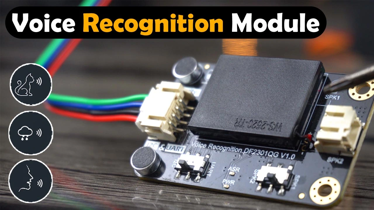
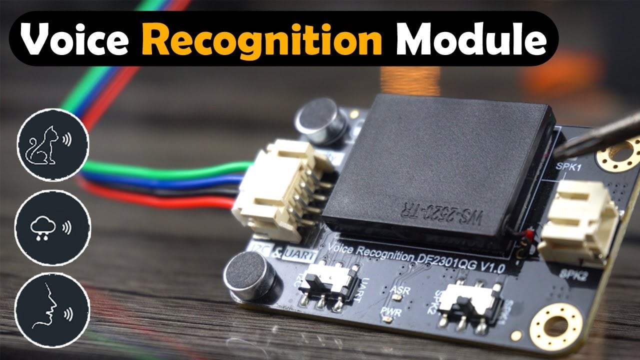
Voice Recognition DF2301QG V1.0:
Features:
This speech recognition sensor module is built around an offline voice recognition chip, which can be directly used without an internet connection.
It comes with 121 built-in fixed command words, eliminating the need for users to record their own voices. Here is a list of all the built-in voice commands with their desired ID’s.
| Fixed Command Words | ID | Fixed Command Words | ID | Fixed Command Words | ID |
| Go forward | 22 | Retreat | 23 | Park a car | 24 |
| Turn left ninety degrees | 25 | Turn left forty-five degrees | 26 | Turn left thirty degrees | 27 |
| Turn right forty-five degrees | 29 | Turn right thirty degrees | 30 | Shift down a gear | 31 |
| Line tracking mode | 32 | Light tracking mode | 33 | Bluetooth mode | 34 |
| Obstacle avoidance mode | 35 | Face recognition | 36 | Object tracking | 37 |
| Object recognition | 38 | Line tracking | 39 | Color recognition | 40 |
| Tag recognition | 41 | Object sorting | 42 | Qr code recognition | 43 |
| General settings | 44 | Clear screen | 45 | Learn once | 46 |
| Forget | 47 | Load model | 48 | Save model | 49 |
| Take photos and save them | 50 | Save and return | 51 | Display number zero | 52 |
| Display number one | 53 | Display number two | 54 | Display number three | 55 |
| Display number four | 56 | Display number five | 57 | Display number six | 58 |
| Display number seven | 59 | Display number eight | 60 | Display number nine | 61 |
| Display smiley face | 62 | Display crying face | 63 | Display heart | 64 |
| Turn off dot matrix | 65 | Read current posture | 66 | Read ambient light | 67 |
| Read compass | 68 | Read temperature | 69 | Read acceleration | 70 |
| Reading sound intensity | 71 | Calibrate electronic gyroscope | 72 | Turn on the camera | 73 |
| Turn off the camera | 74 | Turn on the fan | 75 | Turn off the fan | 76 |
| Turn fan speed to gear one | 77 | Turn fan speed to gear two | 78 | Turn fan speed to gear three | 79 |
| Start oscillating | 80 | Stop oscillating | 81 | Reset | 82 |
| Set servo to ten degrees | 83 | Set servo to thirty degrees | 84 | Set servo to forty-five degrees | 85 |
| Set servo to sixty degrees | 86 | Set servo to ninety degrees | 87 | Turn on the buzzer | 88 |
| Turn off the buzzer | 89 | Turn on the speaker | 90 | Turn off the speaker | 91 |
| Play music | 92 | Stop playing | 93 | The last track | 94 |
| The next track | 95 | Repeat this track | 96 | Volume up | 97 |
| Volume down | 98 | Change volume to maximum | 99 | Change volume to minimum | 100 |
| Change volume to medium | 101 | Play poem | 102 | Turn on the light | 103 |
| Turn off the light | 104 | Brighten the light | 105 | Dim the light | 106 |
| Adjust brightness to maximum | 107 | Adjust brightness to minimum | 108 | Increase color temperature | 109 |
| Decrease color temperature | 110 | Adjust color temperature to maximum | 111 | Adjust color temperature to minimum | 112 |
| Daylight mode | 113 | Moonlight mode | 114 | Color mode | 115 |
| Set to red | 116 | Set to orange | 117 | Set to yellow | 118 |
| Set to green | 119 | Set to cyan | 120 | Set to blue | 121 |
| Set to purple | 122 | Set to white | 123 | Turn on ac | 124 |
| Turn off ac | 125 | Increase temperature | 126 | Decrease temperature | 127 |
| Cool mode | 128 | Heat mode | 129 | Auto mode | 130 |
| Dry mode | 131 | Fan mode | 132 | Enable blowing up & down | 133 |
| Disable blowing up & down | 134 | Enable blowing right & left | 135 | Disable blowing right & left | 136 |
| Open the window | 137 | Close the window | 138 | Open curtain | 139 |
| Close curtain | 140 | Open the door | 141 | Close the door | 142 |
And supports the addition of 17 custom command words. Any sound could be trained as a command, such as whistling, snapping, or even cat meows, which brings great flexibility to interactive audio projects.

IDs from 5 to 21 are already assigned to custom commands.
| Commands for learning | ID | Commands for learning | ID | Commands for learning | ID |
| The first custom command | 5 | The second custom command | 6 | The third custom command | 7 |
| The fourth custom command | 8 | The fifth custom command | 9 | The sixth custom command | 10 |
| The seventh custom command | 11 | The eighth custom command | 12 | The ninth custom command | 13 |
| The tenth custom command | 14 | The eleventh custom command | 15 | The twelfth custom command | 16 |
| The thirteenth custom command | 17 | The fourteenth custom command | 18 | The fifteenth custom command | 19 |
| The sixteenth custom command | 20 | The seventeenth custom command | 21 |
We have a total of 9 learning-related commands which I have explained in the video.
| Learning-related commands | ID | Learning-related commands | ID | Learning-related commands | ID |
| Learning wake word | 200 | Learning command word | 201 | Re-learn | 202 |
| Exit learning | 203 | I want to delete | 204 | Delete wake word | 205 |
| Delete command word | 206 | Exit deleting | 207 | Delete all | 208 |
Wake-up words
| Wake-up words | ID |
| Wake-up words for learning | 1 |
| Hello robot | 2 |
It’s compatible with 3.3V and 5V controller boards like Arduino, Raspberry Pi, ESP32, STM32, ESP8266, and so on.

It supports both I2C and UART communication. You have a switch two select any of the two interfaces.
Since this is an offline voice recognition module, so you don’t need an internet connection which makes it more secure privacy, as users don’t have to worry about their conversation content being recorded and uploaded to the Cloud.
The module features a dual microphone design with better noise resistance and a longer recognition distance, making it relatively accurate and reliable even in noisy environments. I already demonstrated this and it was quite impressive.
It comes with a built-in speaker and an external speaker interface for real-time voice feedback of recognition results. You can use this switch to select the Onboard or external speaker. It supports an external speaker of 8 ohms and 3W passive speaker.
Specification:

Operating voltage: 3.3 – 5V
Maximum Operating Current: ≤370mA (5V)
Communication interfaces: I2C/UART
I2C Address: 0x64
Fixed Commands: 121
Fixed Wake-up Command: 1
Custom Commands: 17 and
Onboard Microphone Sensitivity: -28db

It has a total of 4 wires clearly labeled. If the switch is set to the I2C interface then the Green wire is the SDA and the Blue wire is the SCL. And if the switch is set to the UART interface then the Green wire is the Tx and the Blue wire is the Rx. If you are using a 5V compatible controller board then connect the Red wire to the 5V and GND wire to the controller GND pin. And if you are using a 3.3V compatible controller board then connect the RED and Black wires to the Controller 3.3V and GND pins.
Voice Recognition Module with Arduino:

Connect the VCC and GND wires of the voice recognition module to the Arduino 5V and GND. Since I am using the I2C interface; so that’s why I have connected the Green and Blue wires to the Arduino A4 and A5 pins.
Connect the Red and Brown wires of the Servo to the External 5V regulated power supply and connect the Yellow wire to the Arduino digital pin D2.
Out of these 4 relays I am using only 1 relay and it’s connected to the Arduino digital pin D4.
The 5V buzzer is connected to the Arduino digital pin D8.
You can follow this circuit diagram. Next, I am going to explain how to record a custom wake-up word and voice commands.
Altium Designer, Altium 365, & Octopart:

Altium Designer is the world’s most trusted PCB design system. Altium Designer enables engineers to effortlessly connect with every facet of the electronics design process. Over 35 years of innovation and development focused on a truly unified design environment makes it the most widely used PCB design solution. With Altium Designer you can create PCB designs with an intuitive and powerful interface that connects you to every aspect of the electronics design process. Route it your way through any angle, tune for the delay, Push, Slide, and Walkaround faster than ever.
Easily work together with your mechanical team and forget about the days of swapping design files. Every design change stays in sync between Altium Designer and SOLIDWORKS, PTC Creo, Autodesk Inventor, Autodesk Fusion 360, or Siemens NX*.
Interact and collaborate with mechanical designers like never before in a photo-realistic, 3D design environment.
One of the best things about Altium Designer is that you can share your designs with your team members using Altium 365. They can check your design, leave comments, and if there are any issues, they can fix them from anywhere in the world. Altium Designer also uses the world’s fastest components search engine, Octopart, so you won’t have any difficulty in searching for components.
Altium Designer, Altium 365, and Octopart—unleashes the full potential of electronics design by seamlessly integrating design tools, collaboration platforms, and component databases. Together, they offer engineers a comprehensive and synchronized experience, leading to improved productivity, reduced errors, and accelerated innovation in the world of electronics design.
Recording a custom voice command:
We have a total of 9 learning-related commands. Let’s say if you want to record a new wake-up word or a phrase then simply say learning wake word and then follow the voice assistant.
Watch Video Tutorial
Now, I can use the “Hi sexy” command to wake-up the module.
Now let’s record 4 custom voice commands; for this we will have to say Learning command word and then we will have to follow the voice assistant. So, let’s do it.
Watch the Video
After you have recorded the voice commands don’t forget to say Exit learning.
Exactly the same way, you can record other voice commands. Let me remind you, you can only record 17 custom voice commands.
Delete Wake Words and Command Words:
Summon the voice assistant using the awakening word (default or customized), and articulate the phrase “I want to delete” Follow the prompts to eliminate the specified command phrase as instructed.
Indication: Do you want to delete the learned wake word or command word?
Delete command word: Remove the previously acquired command phrases.
Delete wake word: Erase the learned awakening words from the system.
Delete all: Eliminate the assimilated awakening utterances and command phrases from memory.
Exit deleting.
Anyway, next, I am going to explain how to use the Built-in and custom commands in the programming to control anything we want. But, first, I am going to install the required library.
Voice Recognition Module Library:
Download: DFRobot_DF2301Q library
While the Arduino IDE is opene. Go to the Sketch Menu, then to Include Library, and click on the Add .zip Library.

Browse to the location and select the library zip folder and click on the open button.

Voice Recognition Module Arduino Programming:
|
1 2 3 4 5 6 7 8 9 10 11 12 13 14 15 16 17 18 19 20 21 22 23 24 25 26 27 28 29 30 31 32 33 34 35 36 37 38 39 40 41 42 43 44 45 46 47 48 49 50 51 52 53 54 55 56 57 58 59 60 61 62 63 64 65 66 67 68 69 70 71 72 73 74 75 76 77 78 79 80 81 82 83 84 85 86 87 88 89 90 91 92 93 94 95 96 97 98 99 100 101 102 103 104 105 106 107 108 109 110 111 112 113 114 115 116 117 118 119 120 121 122 123 124 125 126 127 128 129 130 131 |
#include "DFRobot_DF2301Q.h" #include <Servo.h> Servo servo; #define light 4 // relay is connected to the digital pin D4 #define buzzer 8 // buzzer is connected to the digital D8 //I2C communication DFRobot_DF2301Q_I2C asr; // activates the I2C mode of the voice recognition module void setup() { Serial.begin(115200); pinMode(light, OUTPUT); //Init light pin to output mode pinMode(buzzer, OUTPUT); //Init buzzer pin to output mode digitalWrite(light, LOW); //Set light pin to low digitalWrite(buzzer, LOW); //Set buzzer pin to low servo.attach(2); // Servo is connected to the digital pin D2 // Init the sensor while (!(asr.begin())) { Serial.println("Communication with device failed, please check connection"); delay(3000); } Serial.println("Begin ok!"); /** * @brief Set voice volume * @param voc - Volume value(1~7) */ asr.setVolume(7); /** @brief Set mute mode @param mode - Mute mode; set value 1: mute, 0: unmute */ asr.setMuteMode(0); /** @brief Set wake-up duration @param wakeTime - Wake-up duration (0-255) */ asr.setWakeTime(20); /** @brief Get wake-up duration @return The currently-set wake-up period */ uint8_t wakeTime = 0; wakeTime = asr.getWakeTime(); Serial.print("wakeTime = "); Serial.println(wakeTime); asr.playByCMDID(1); // Wake-up command /** @brief Play the corresponding reply audio according to the ID @param CMDID - command word ID */ //asr.playByCMDID(23); // Command word ID } void loop() { /** @brief Get the ID corresponding to the command word @return Return the obtained command word ID, returning 0 means no valid ID is obtained */ uint8_t CMDID = asr.getCMDID(); Serial.println(CMDID); switch (CMDID) { case 103: //If the command is “Turn on the light” digitalWrite(light, HIGH); //Turn on the light break; case 104: //If the command is “Turn off the light” digitalWrite(light, LOW); //Turn off the light break; case 141: // open the door servo.write(90); delay(3000); break; case 142: // close the door servo.write(0); delay(3000); break; case 88: // turn ON the buzzer digitalWrite(buzzer,HIGH); break; case 89: //Turn off the buzzer" digitalWrite(buzzer,LOW); break; // Custom commands in English case 5: // Servo 90 servo.write(90); delay(3000); break; case 6: // Servo Zero servo.write(0); delay(3000); break; //Custom commands in Urdu/Hindi Language case 7: // light ON karo digitalWrite(light, HIGH); //Turn on the light break; case 8: // light OFF karo digitalWrite(light, LOW); break; default: if (CMDID != 0) { Serial.print("CMDID = "); //Printing command ID Serial.println(CMDID); } } delay(300); } |
103 is the ID of “Turn ON the light”. You can confirm this from the built-in commands list. You can see 104 is the ID of “turn off the light”. So, I have used the same ID in the programming to turn off the light.
Similarly, 141 is the ID of “Open the door” and 142 is the ID of “Close the Door”.
88 and 89 are the IDs to turn ON and turn off the buzzer.
5, 6, 7, and 8 are the IDs of custom voice commands. And let me tell you, whenever you start learning command words; it will start from the first command. So, each time you add a new command, you will have to record the previous voice commands as well. So, what I suggest is that, first write all your custom voice commands on a paper and then record those in one go. This is how I did it and it worked and I have already demonstrated this. So, That’s all for you.
Watch Video Tutorial:
Discover more from Electronic Clinic
Subscribe to get the latest posts sent to your email.


Hi
I have tried your code but am stuck – any chance you can find the time to help me please?
I am using Arduino ide v2.2.1 on a Linux system
When i run your code the serial monitor just keeps outputting the number 0 over & over on a new line
Although the DFRobot board gives an audio response to my instructions nothing lights up & nothing is printed in the serial monitor
I have tried the demo code from the DFRobot library & i get the a simiklar result in that the serial monitor does not print out anything
Any guidance you could give would be much appreciated!