500W Ebike Brushless Motor Controller wiring explanation, Hoverboard Test
Last Updated on October 3, 2024 by Engr. Shahzada Fahad
Table of Contents
500W Ebike BLDC Motor Controller, Description:
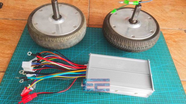
500W Ebike Brushless Motor Controller wiring explanation, Hoverboard Motors Test- In this article, you will learn how to use this 36V to 48Volts 500W Ebike or Electric Bike Brushless Dc Motor Controller with the Hoverboard 350 Watts BLDC motors. Basically, this article is about the wiring explanation of the Brushless Motor Controller. I will explain how to use each and every wire with a practical demonstration. You can also watch the video tutorial given at the end of this article.
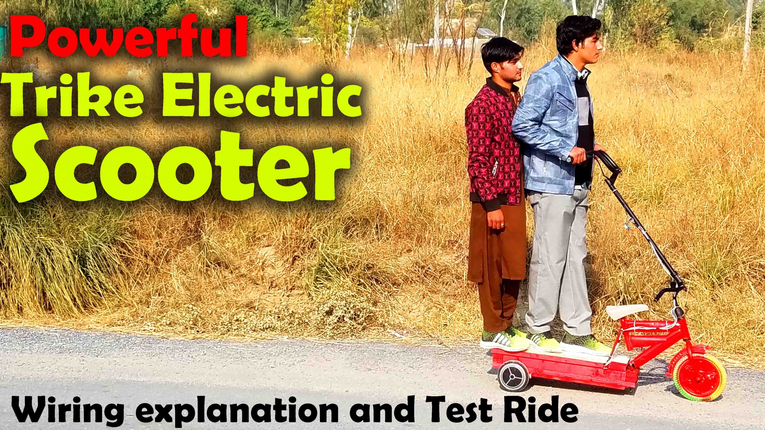
Read my article on how to make Trike Electric Bike using 500Watts BLDC Motor controllers and Hoverboard Motors. In this article, I have explained how to control two BLDC motors using only one throttle handle.
I will also explain how to use the Ebike throttle handle to control the speed and the buttons to switch ON and switch OFF the control system and how to switch among 3 different speeds. So, this article is going to be very informative and I will try my level best to clear all your confusion. Before, I am going to explain anything first a few words about the sponsor.
Altium Designer:

Altium Designer is the world’s most trusted PCB design system. Altium Designer enables engineers to effortlessly connect with every facet of the electronics design process. Over 35 years of innovation and development focused on a truly unified design environment makes it the most widely used PCB design solution. With Altium Designer you can create PCB designs with an intuitive and powerful interface that connects you to every aspect of the electronics design process. Route it your way through any angle, tune for the delay, Push, Slide, and Walkaround faster than ever. Interact and collaborate with mechanical designers like never before in a photo-realistic, 3D design environment. If you want to get started with the Altium designer, you can click on the get started.
Don’t get confused or worried if you see these lots of wire, because more wires means more functions, and seriously this Ebike Brushless Motor Controller has got many functions including the Switch ON and OFF, Motor Direction Control programming, Anti-theft system, Brake, Cruise control system, Low, medium, and high speed selection, Motor Reverse, Motor speed controlling using Ebike throttle handle of any type, Hall sensor connection, etc. We will take a closer look at each one and we will practically connect all these wires. Without any further delay let’s get started!!!
Amazon Links:
500W 36/48V Brushless Motor Controller
Yaegoo 500W 36 to 48V Brushless Motor Controller
Disclosure: These are affiliate links. As an Amazon Associate I earn from qualifying purchases.
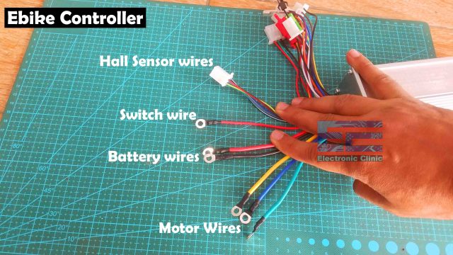
Ebike BLDC Motor Controller:
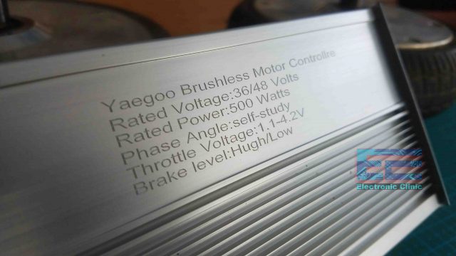
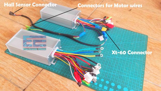
Here I have this Yaegoo Ebike Brushless Motor Controller. The rated voltage is 36 to 48 Volts. The rated power is 500 Watts with phase angle self-study and the throttle voltage is from 1.1 to 4.2 volts. So, with this Ebike Brushless Motor Controller you can control almost all types of BLDC motors which are up to 500 Watts and 36 to 48 volts.
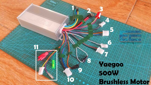
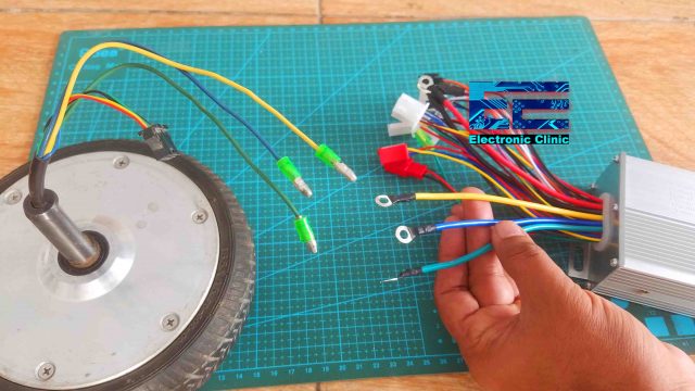
- Motor three phases Green, Blue, and Yellow.
- The two thick Red and Black wires are the power supply wires, the other think red wire is the switch wire which needs to be connected with the main voltage wire.
- Anti-theft wires, Red wire is the main voltage wire while the Yellow and Blue wires are the signal wires.
- BLDC Motor Reverse wires. These are Black and Grey color.
- Hall Sensor Wires.
- Brake wires.
- Throttle wires.
- Motor direction programming wires.
- Cruise control system wires.
- Speed selection wires.
- These 4 sets of wires carries the system voltage. By system voltage I mean the battery main voltage.
We will talk about these in detail.
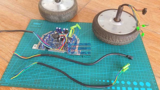
Previously, I salvaged these 350 watts BLDC motors from a dead Hoverboard along with this circuit which has lots of wires which I will reuse today.
BLDC motor 3 phases:
If you take a look at the motor wires it has these three wires Green, Blue, and Yellow. The same wires you will also find on the Ebike Brushless Motor Controller, we have these three thick wires Green, Blue, and Yellow. You will find the same colors on almost all types of the Ebike controllers.
To connect the motor all you need is to connect the Motor Green wire with the controller Green wire, Motor Blue wire with the controller Blue wire, and similarly the Motor Yellow wire with the Controller Yellow wire. We will do connections in a minute.
Hall Sensor Wires:
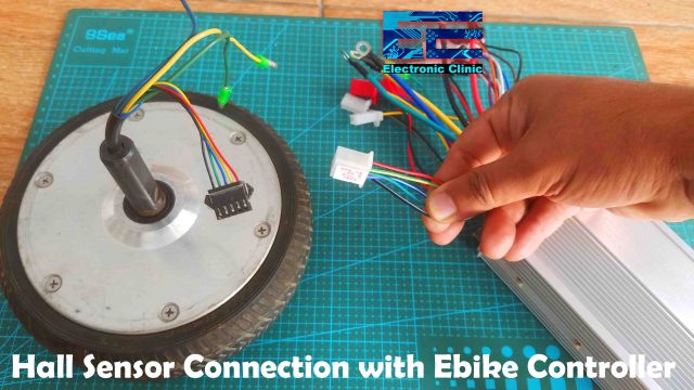
On the motor you can see these wires which are the hall sensor wires. These are mostly 5 wires with colors Red, Yellow, Blue, Green, and Black. You can neglect any extra wire. Sometimes there are 6 wires. So, any other color wire other than the Red, Yellow, Blue, Green, and Black simply ignore it. Anyway, these 5 wires are need to be connected with the Hall sensor wires on the Ebike controller.
On the Ebike controller I have only this one connector with 5 wires. On this connector Chinese is written, so I used the Google translator and I confirmed it, so these wires are the Hall Sensor wires. These wires have got the same colors Red, Yellow, Blue, Green, and Black. These are color coded which makes it extremely easier to connect. All you need is to connect the same colors. Red with Red, Yellow with the Yellow, Blue with the Blue, Green with the Green, and finally Black with the Black wire.
Power Supply Wires:
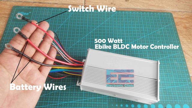
These two thick Red and Black color wires are the power supply wires and these are need to be connected with the 36 volts battery pack.
Switch Wire:
This other red wire is the switch wire which activates and de-activates the entire control system. When this wire is connected with the battery voltage it activates the control system and when disconnected the control system is de-activated. Now, you have two options you can connect this wire with this thick red wire and your control system will be activated permanently. Or you can connect this thin red wire with a switch and you can activate and de-activate the control system whenever you want. I will connect it with the throttle handle switch.
So far, we have covered the Motor three phases, the power supply wires, the switch wire, and the hall sensor wires. Now, it’s time to practically start connecting these wires.
Brushless Motor Controller Wiring:
The wire connectors on the Motor and on the Ebike controller are completely different and are hard to connect, I don’t want to solder these wires. I will cut these connectors and will connect it with the wires which I salvaged from the Hoverboard control board.
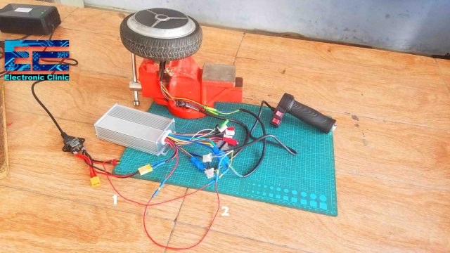
I will also cut the connectors from the battery wires and will connect the XT-60 connector and this way I can easily connect and disconnect a battery.
I have these two Electric Bike Brushless Motor Controllers. I modified this one Ebike controller which now I can easily connect with the Hoverboard BLDC Motor. First I am going to connect the motor wires, I am just connecting the same color wires together. Next I am going to connect the Hall Sensor connector, and Finally, I am going to connect the Power supply. Right now I don’t have a battery pack, but I have a 36 to 48 volts battery charger which I am going to use for the testing.
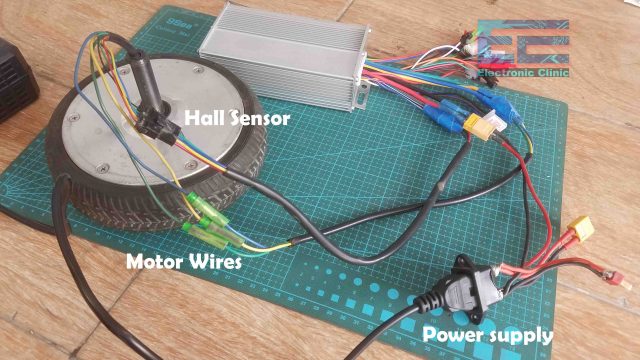
So, we have this basic setup completed. The motor 3 phases are connected, the hall sensor is connected and the power supply is connected.
Throttle Wires:
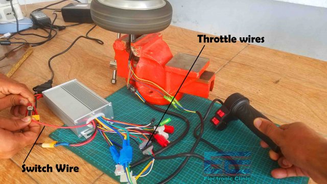
Now, to control the BLDC motor we need to find the throttle wires which are always Red, Green, and Black.
The same color wires you will also find on the throttle handle. I had different connectors on both the sides so that’s why I soldered male and female headers and now I can easily connect the throttle handle.
Now, with all this basic setup I can start controlling the BLDC motor and this is what I am going to demonstrate now.
So, let’s go through all these connections one more time to avoid any confusion. My Power supply is connected, the BLDC motor three phases are connected, the Hall sensor is connected, and the Throttle handle is connected.
When this red color switch wire”switch wire” is not connected with the system voltage which is the battery main voltage, the control system will remain de-activated, and you won’t be able to control the speed of the BLDC motor using the throttle handle. But when I connect the switch wire with the battery voltage then I can start controlling the motor. It’s just that simple. As I explained earlier you can permanently connect this wire”switch wire” with the battery voltage main wire, or you can connect this wire with a switch to manually activate and de-activate the control system. So, let’s go ahead and connect this wire with a switch.
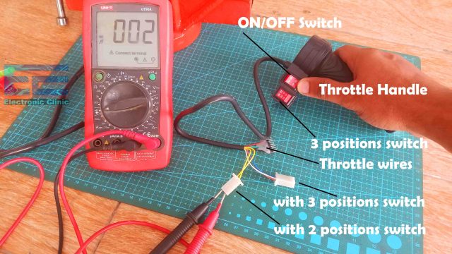
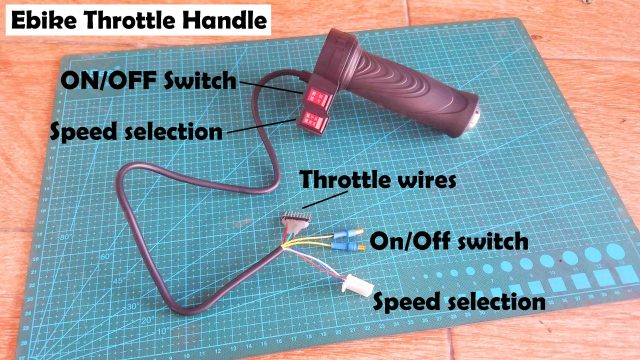
On the throttle handle you can see we have these two buttons or switches. This one is a simple two positions switch and the other one is a 3 positions switch. So, we are going to use this two positions switch. This is just a simple ON/OFF switch which you can confirm by using a digital Multimeter. Set beep on the digital Multimeter and connect the two test leads with the two wires, now when you press the button you should hear the beep sound. So we can use this button to connect and disconnect the battery voltage with the switch wire. So, let’s do the wiring.
Connect the voltage wire with the one side and connect the other side with the Red color switch wire. Now you can use this button to activate and de-active the control system.
I have marked these two wires with numbers 1 and 2. You can clearly see the wire number 1 is connected with the 36/48volts and one wire of the on/off switch, while the wire number 2 is connected between the switch wire and the other wire of the ON/OFF switch. So, this ON/OFF switch on the throttle handle simply short the two wires and this way the main system voltage is connected with the switch wire.
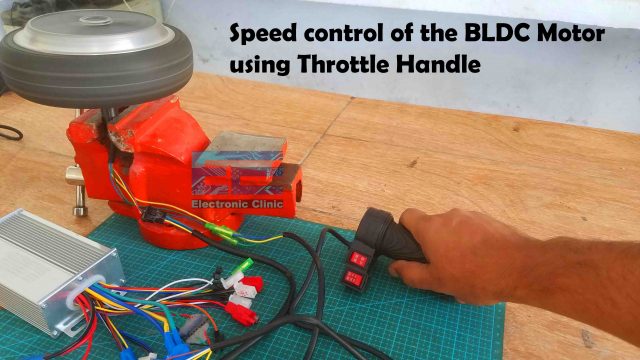
Now you can clearly see, the switch is ON and I am controlling the speed of the BLDC Motor using the throttle handle.
Motor Direction Programming:
Next, we are going to talk about the motor direction control. We can actually program it. Right now you can see the motor is rotating in this direction “will in the image you can’t see the direction, but in the video you will clearly see”, and what if you want to change the direction?
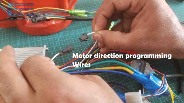
For this we have these two wires which can be used to program the direction of rotation of the BLDC motor. To program it, all you need is to connect these two wires while the switch is ON and the motor will immediately start rotating in the other direction… Now, first disconnect the two wires and then turn OFF the switch… Now, the control system will remember in which direction the motor was rotating. Now you can turn ON the switch and start controlling the motor, but this time the motor will be spinning in the other direction… Now, if again you want to change the direction of rotation, you can repeat the same steps…these wires are only used when you are programming the direction; these wires have no other use and are left unconnected.
Speed Limit:
Next, we are going to talk about the speed limit.
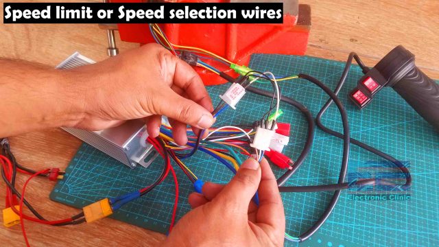
We have this connector with the Blue, Brown, and Black wires. Blue and Brown wires are the signal wires while the Black wire is the ground wire. We can use these wires to set the low, medium, and maximum speed. When these wires are not connected the motor spins at a medium speed.
On the throttle handle we have this 3 positions switch, it has this connector with Blue, White, and Brown wires. On this connector the white wire is the ground wire. Connect the Black wire with the White wire… connect the Blue wire with the Blue wire… and finally, connect the Brown wire with the Brown wire… Now using the 3 positions switch you can set the speed limit…
If you are using a throttle handle which has no three positions switch then you can simply leave this connector unconnected or if you have to set the speed limit then all you can do is simply connect the black wire with the Blue or Brown wire to set the speed limit. Now, this can be useful when you are making an electric scooter or bicycle for the kids. You can set low speed permanently.
Brake Wires:
These Black and White wires are the brake wires. When these two wires are connected the motor will stop spinning.
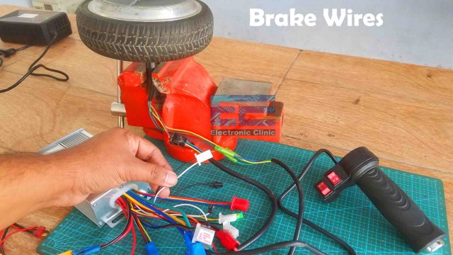
To test this, simple use the throttle handle to increase the speed of the BLDC motor and then short the white and black wires together, it will stop the motor. It can be used with the mechanical brake in a way that when the brake is applied the two wires are get connected, so this way even if the switch is on or if the motor is spinning at high speed through the throttle handle, the control system will ignore the throttle handle and the brake will be implemented. This will protect the motor from any damage. Imagine when you hold the throttle and meanwhile you applied the mechanical braked what will happen?
BLDC Motor Reverse wires:
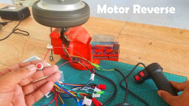
These Black and Grey wires are the BLDC motor reverse wires. So, when these wires are connected together the motor will start spinning in the reverse direction. Now, this can be very useful when you are building an electric car or go kart, just press the button and reverse the car. Press the button and apply the throttle and the motor will start spinning in the reverse direction.
Anti-theft Wires:
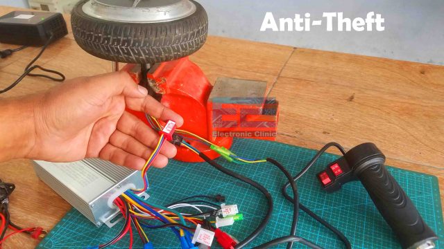
This connector is for the Anti-theft. The Red wire has the battery voltage. Blue wire is the signal wire and the Yellow wire is the ground wire. So, to enable the anti-theft, simply connect the Blue and Yellow wires together… While the anti-theft is enabled, even if the switch is ON the motor won’t start. To use this you can secretly install a button or you can make your own Bluetooth based relay board and then you can use your cell phone to enable and disable the anti-theft function on your electric scooter or electric bike.
Cruise Control System:
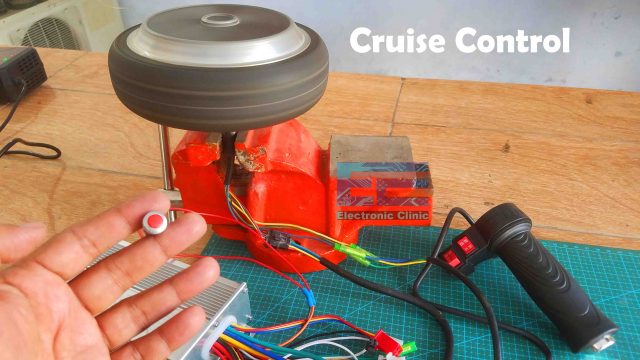
These Black and Orange color wires are the Cruise control system wires. You can think of it as the handsfree system. It simply locks the motor speed. To demonstrate this I connected a pushbutton with these two wires. As you know using the throttle handle we can select any speed, let’s say I want to move with this speed and I don’t want to hold the throttle handle at all the times, so what I can do, I will simply press the push button and it will lock the motor speed and now I can remove my hand and the motor will continue to spin at the same speed… This is simply amazing. Now to de-activate the cruise control system, simply rotate the throttle handle or press the pushbutton one more time.
Finally, the remaining 4 sets of wire carries the system voltage which you can use to power up the lights and other electronic circuits. If there is any confusion you can watch the video tutorial given below. Don’t forget to subscribe my YouTube channel. You can support me by liking and sharing the video.
Watch Video Tutorial:

Discover more from Electronic Clinic
Subscribe to get the latest posts sent to your email.


This is a great explanation but can you run two motors off one controller ?
Can you use two motors off one controller
I have a 6th hall wire and it is white. Do you know what is used for ?
You can.
“Hover 1 helix” (I do not own in any regard) They have it set up with 2 wheels 1 logic board /controller. And 2 information boards. (I donot suggest doing this. Im an elecrician of 17 years) I modified mine. Added a battery pack and converted it to use 1 board. I have one for a spare i also put a small fan on the board to cool it. Hope that help your question
Hello Shahzada Fahad,
Thank you for your easy to understand explanation, I especially liked your recommendation of an anti theft device by relay board and blue tooth (I may do this in future)
My question is what happens if you have no switch wire?
My controller
https://www.ebay.com/itm/115591433726
Thank you very much!
Bill
How do i connect this same motor to run in clockwise direction with a 36v adapter with just black and red supply wires?