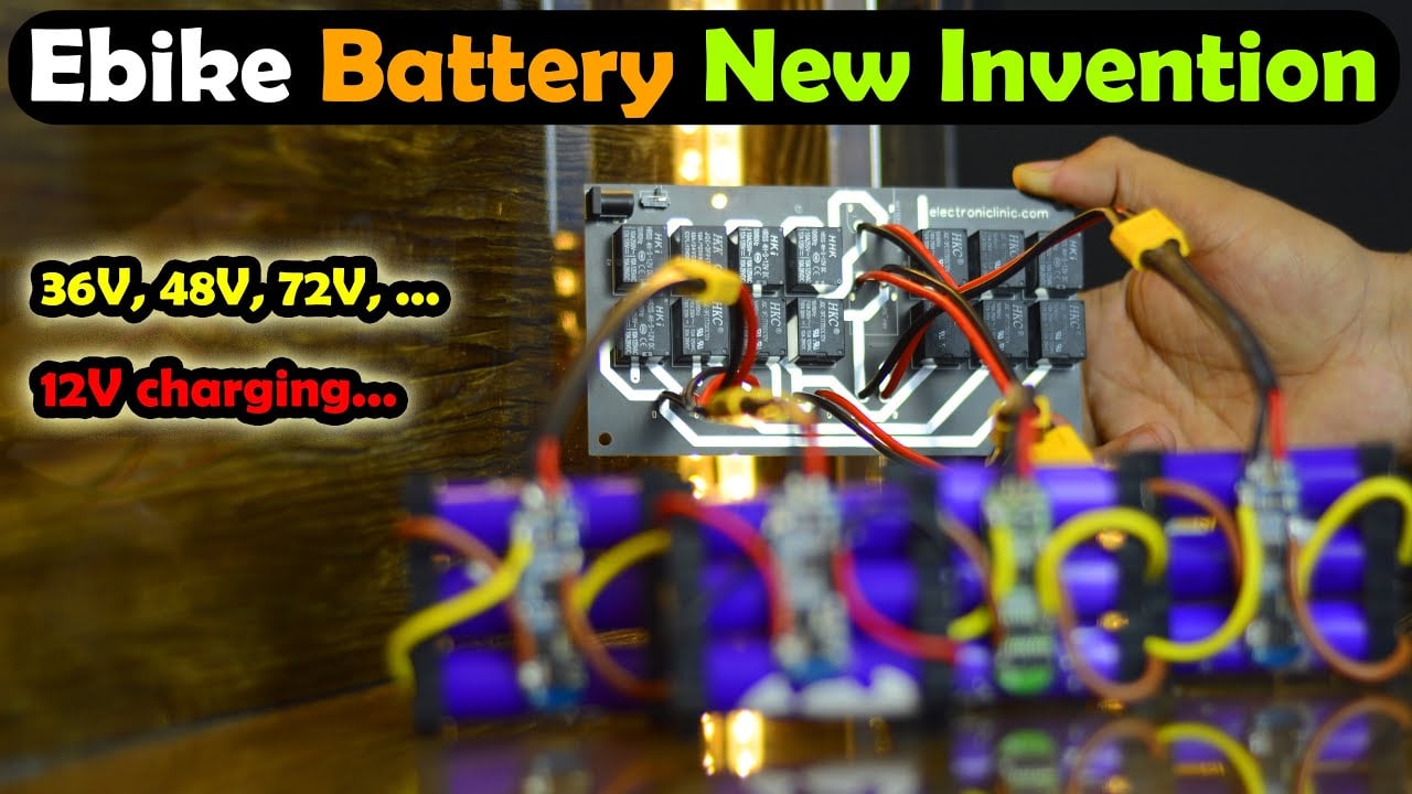
Ebike Battery New Invention, 36V, 48V, and 72V Ebike Battery
36V, 48V, and 72V Ebike Battery charging with 12V
Last Updated on September 21, 2024 by Engr. Shahzada Fahad
Table of Contents
Ebike Battery New Invention:
Ebike Battery New Invention, 36V, 48V, and 72V Ebike Battery– This Ebike Battery New Invention is going to blow your mind; because using this circuit you can make 36V, 48V, 72V, or even a higher voltage Ebike battery. And I am going to share with you every bit of information, it’s designing, Proteus simulation, soldering, and practical testing. I know you might be thinking; why have I connected 4 battery packs? Why not a single battery pack? Is it cost-effective? Well, you will get answers to all your questions. So, let me start by telling you why I needed to make this in the first place?
Amazon Links:
Disclosure: These are affiliate links. As an Amazon Associate I earn from qualifying purchases.
Large battery packs like these are very expensive and for beginners, it’s hard to make a 36V or 48V, or 72V Ebike battery. Because connecting these so many lithium Ion Batteries in series and parallel combinations and then connecting them to a single BMS “Battery Management System” is the hardest job. I myself, when I built my first Trike Electric Scooter for performing some experiments; I used 4 Lead Acid batteries in series to get 48 volts. Of course, these were expensive and too heavy.
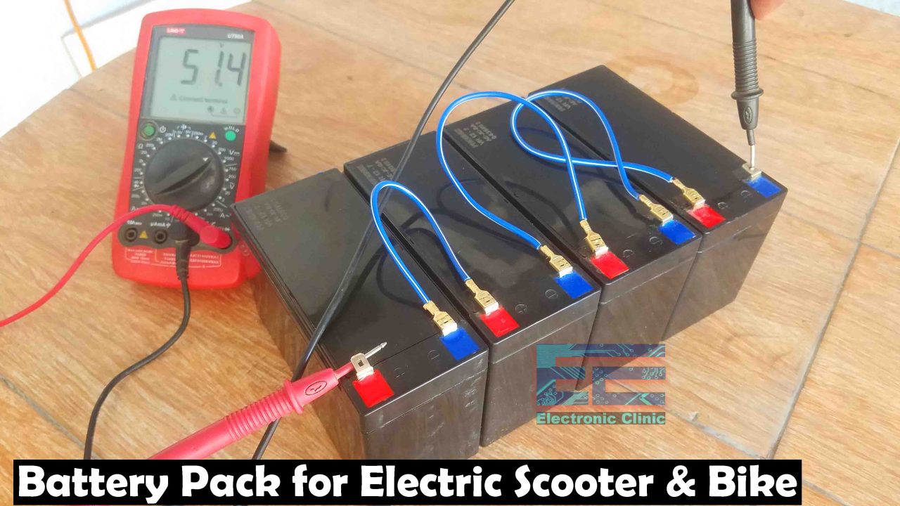
Anyhow, at that time this was the easiest solution that I could think of. Even with this easiest solution, the next issue which I faced was charging this 48V battery pack. So, I bought myself a 48V charger which is expensive and not easily available like 12V adaptors.
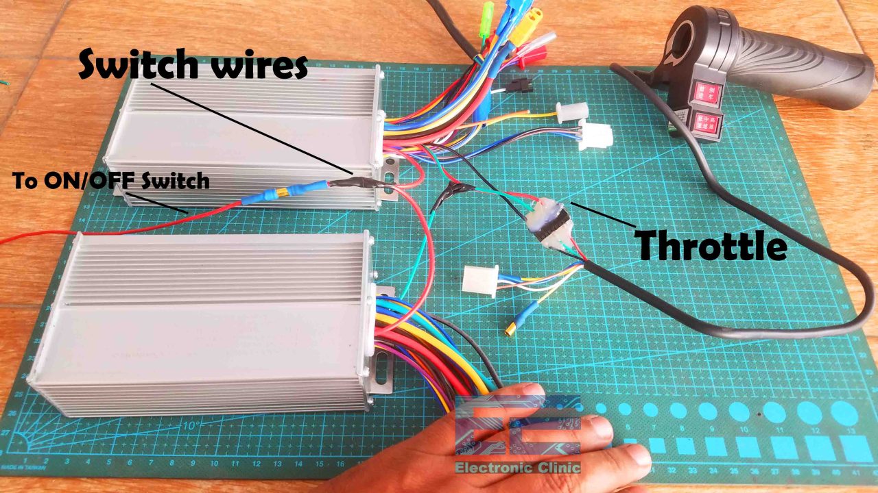
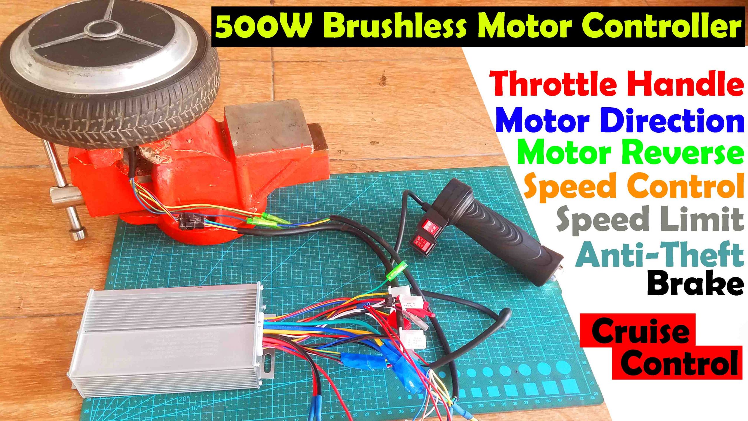
I ordered this online and then I had to wait for 3 days. Anyway, I performed all my experiments, first I started with a single Hoverboard BrushlessMotor, I successfully controlled it using a throttle handle and then using two 500Watts controllers I controlled two Brushless motors using the same throttle handle.
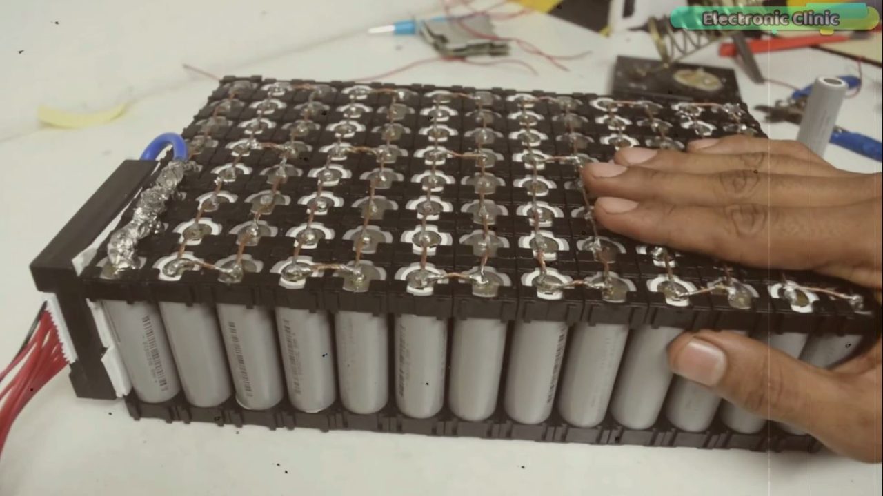
Next, I studied different Battery management system modules. And I built myself 3S and 4S Lithium Ion Battery Packs as these were easy to start withand moreover at that time I only needed 3S and 4S battery packs.
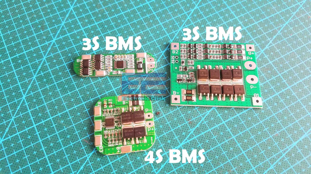
You can read my article on how to make 3S and 4S lithium Ion Battery packs, I have pretty much explained everything the connections diagram, welding using my designed spot welding machine and I have also explained how to do soldering if in case you don’t have a spot welding machine. So, if you are just starting with Lithium Ion battery packs then you should read my previous articles.

Anyway, after practicing for a while; finally, I was ready to make a 4S lithium Ion Battery pack for my Racing Drone as I was tired of using Lipo batteries. Lipo Batteries could hardly give me 5 to 6 minutes of flight time while my designed 4S lithium Ion battery pack gave me 30 minutes of flight time.
Based on my previous knowledge and experience, I built this 48V battery pack. This is cost-effective and can be easily built by anyone, and this 48V battery pack can be charged using a 12V adopter or a solar panel.
If you make a large 48V battery pack like this then you will need a 13S BMSwhich is available in the range of 3000 to 4200Rs on Pakistani online stores and it’s also quite expensive on Amazon. While on the other hand 3S and 4S BMSmodules are quite cheap. I am going to need four3S BMS modules which will cost me only 1600Rs or 7.17 USD. So, it will save me 2600Rs. And if you purchase these 3S BMS modules on Amazon then it will save you 50USD. Even if you search for the cheapest 13S BMS modulestill you will be saving yourself a lot of money.
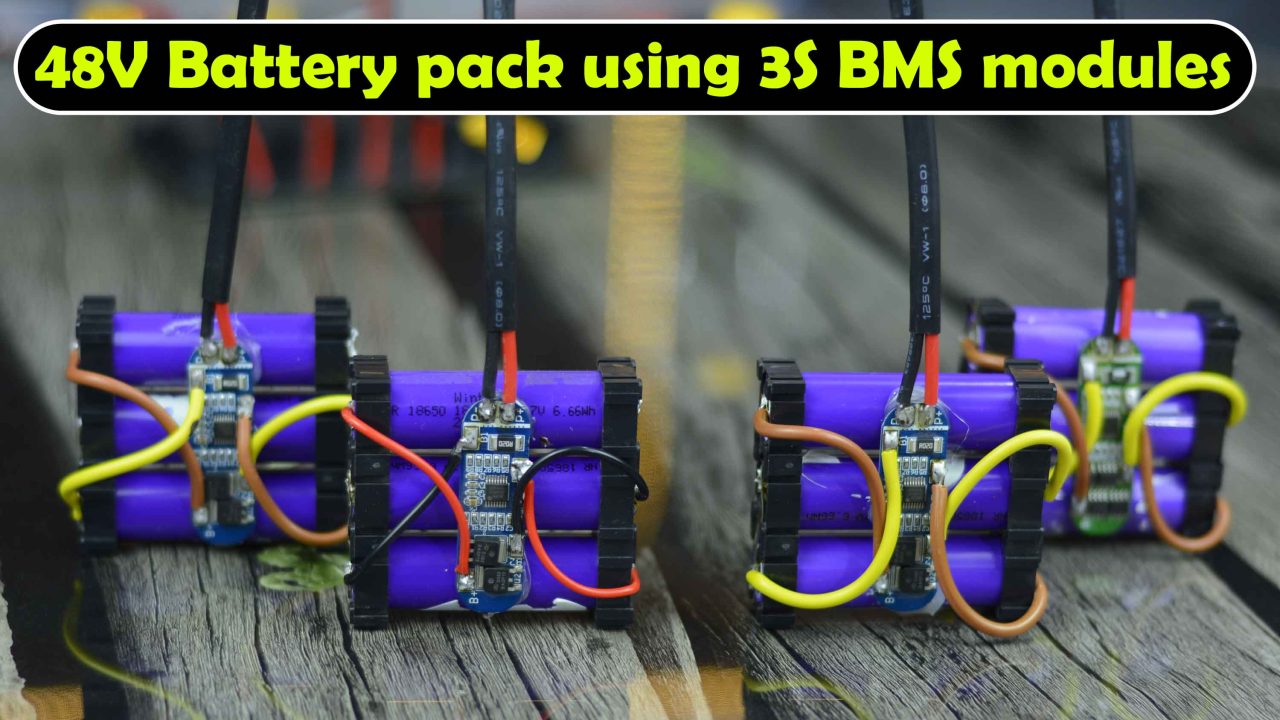
So, using these 3S BMS modules I built myself these 3S Lithium Ion Battery Packs. You can read my article on how to make 3S and 4S lithium Ion Battery packs using 3S and 4S BMS modules. Anyway, now I can connect these 4 battery packs in Series to get 48 volts.
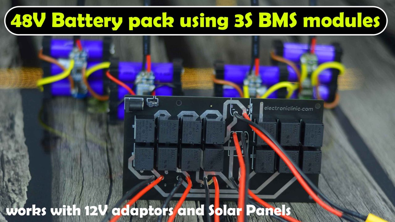
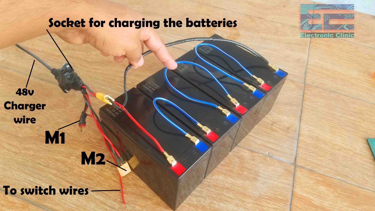
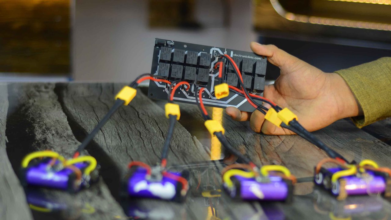
For this I designed this Semi-automatic control circuit. Its job is to connect all these batteries in series when needed to power up the Electric Bike or Electric Scooter and to charge the battery packs using a low-cost 12V adaptor. You don’t need a 50V or a high volt charger. A 12V and 3 to 4 amps adaptor is more than enough or if you want you can also use a solar panel. Now, you might be thinking how am I charging a 48V battery pack with a 12V adaptor? Well, it’s simple let me explain this by connecting all the 4 battery packs.
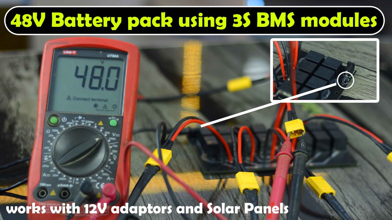
I have designed this circuit in a way that when this switch is OFF, all the batteries are connected in Series, and on the output, I get 48 volts.
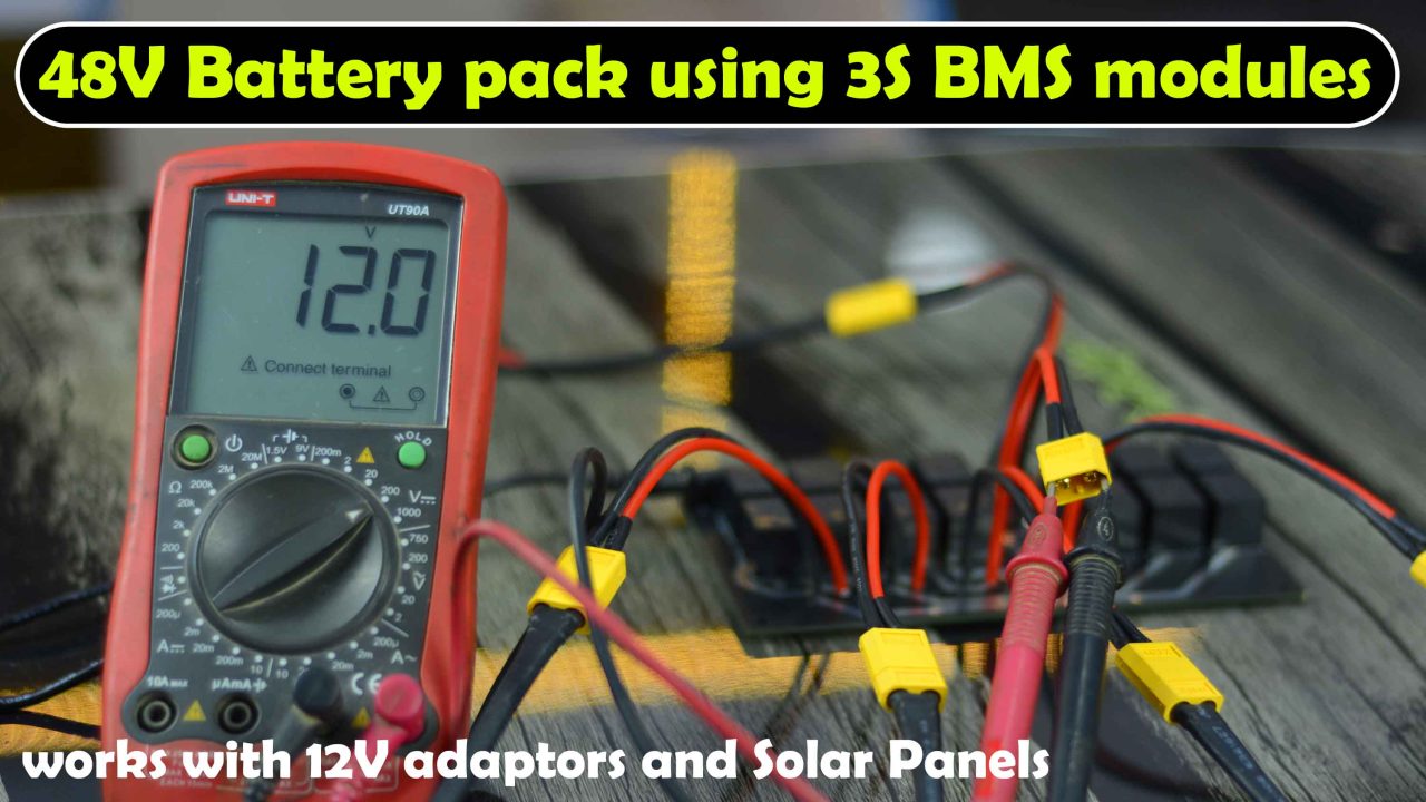
And when I turn on this switch then all the batteries are connected in parallel. Now, I can use my 12V adaptor or a solar panel to charge all the batteries. At the same time, you can either charge the batteries or use them to power up the Ebike. This limitation is on the BMS side, I have already explained this in my previous video and article.
Anyway, this is a fully working prototype model. If you don’t like using the relays, then you can use power MOSFETs to implement the same concept. This circuit works with 1s, 2s, 3s, 4s, 5s, 6s, 7s, 8s, 9s, 10s, 11s, 12s, 13s, 14s, and so on. It depends on you how much voltage you need on the output.
When it comes to troubleshooting of this 48V battery pack it’s very easy. You can individually check each battery pack and if there is something wrong you can replace that battery pack with a new one or you can simply replace the faulty cell and you are good to go.
While on the other hand if one or more cells are damaged in a large battery pack then you will need to de-solder all the cells to find the faulty cells, which is really a tedious job.
Now, you know the advantages of this new 48V Ebike battery system, and now I am going to explain its simulation, PCB designing using Altium Designer, Online order placement on JLCPCB, Soldering, and practical testing. So, first, let’s start with the simulation.
48V Battery Pack Proteus Simulation:
Download Ebike Battery Simulation
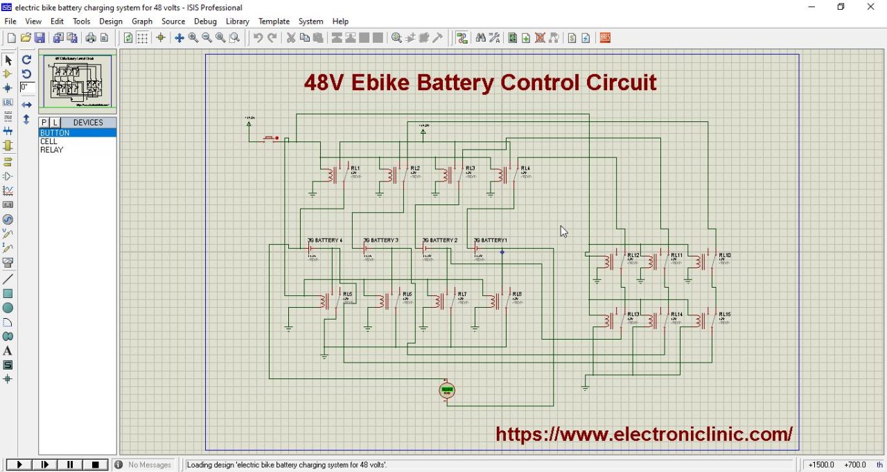
Before designing the PCB, I designed this simulation in Proteus. Let me play this simulation.
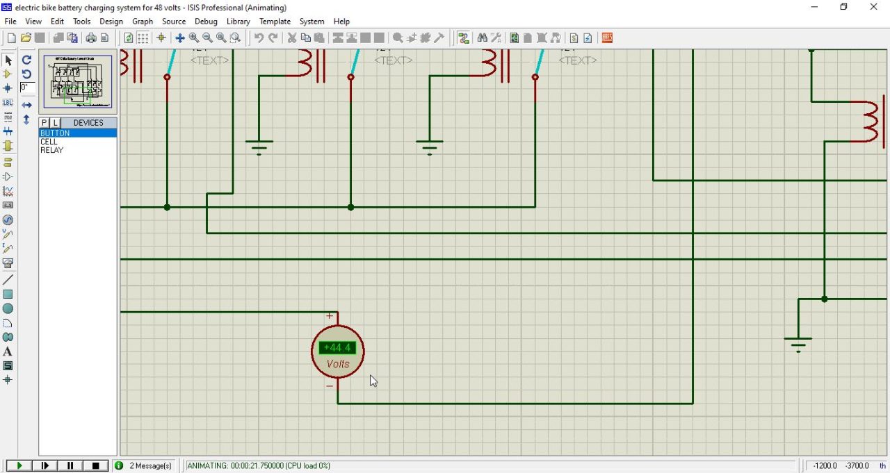
when the button is OFF the circuit is completely dead and on the output it gives 48 volts, right now you can see 44.4 volts but when the batteries are completely charged you will see 48 volts, I already demonstrated this. So, when the button is OFF the circuit consumes no electricity and you get full output as all the battery packs are connected in series.
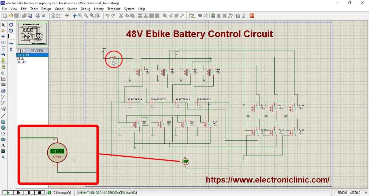
When the switch is turned ON, all the batteries are connected in parallel and on the output you will see 11.1 volts. This voltage may vary depending on how much charge is available. Anyway, when the switch is ON simply connect your 12V adapter or solar panel to charge all the 4 lithium ion battery packs. So, after successfully implementing this idea in Proteus, then I switched over to Altium Designer for designing the PCB.
48V Battery Pack PCB designing in Altium Designer:
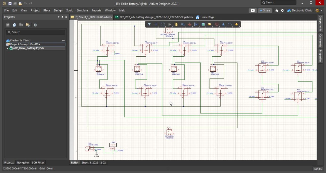
Before creating the schematic and designing the PCB in Altium Designer, first I started off by searching the components on the world’s fastest components search engine Octopart. I selected the desired components with footprint models and used them for creating the schematic as per the simulation. I already have a very detailed video on how to make a schematic and PCB using Altium Designer.Anyway, then I switched over to the PCB designing document, I defined the PCB board size and re-arranged all the components.
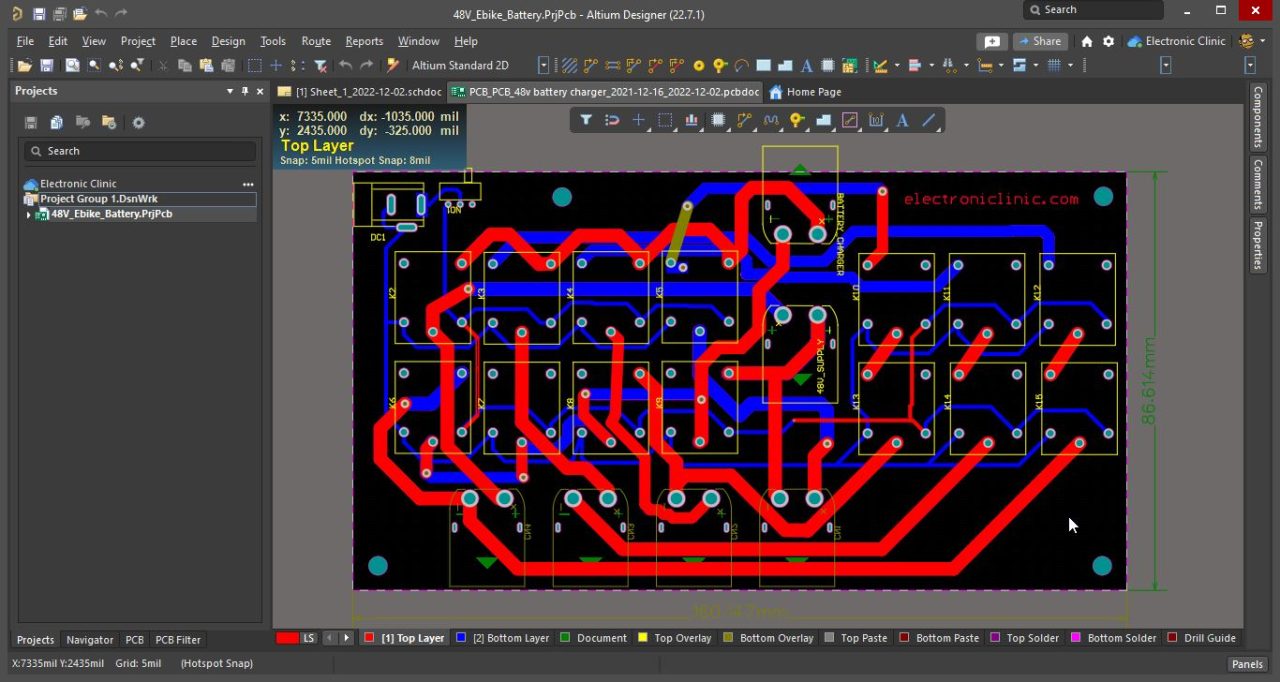
Using Altium Designer you can automatically route all the wires. But I did it manually. I increased the width of the wires and I also applied solder to the top and bottom traces to increase the current carrying capacity as most of the current will be following through these copper traces.
I have used a total of six XT60 connectors. These 4 connectors on the bottom side are used to connect the four battery packs. From the middle one, we get the output to power up the Electric bike or Electric Scooter. And the one on the top is used to charge all the four battery packs using a 12V adaptor.
Finally, before generating the Gerber files, I activated the 3D layout mode by clicking on number 3 on the keyboard. I double checked all the connections and once satisfied. I again activated the 2D layout mode by clicking on number 2 on the keyboard. Finally, I was ready to generate the Gerber files.
Generate Gerber Files using Altium Designer:
For this click on the file menu and then go to Fabrication Outputs and click on the Gerber Files.
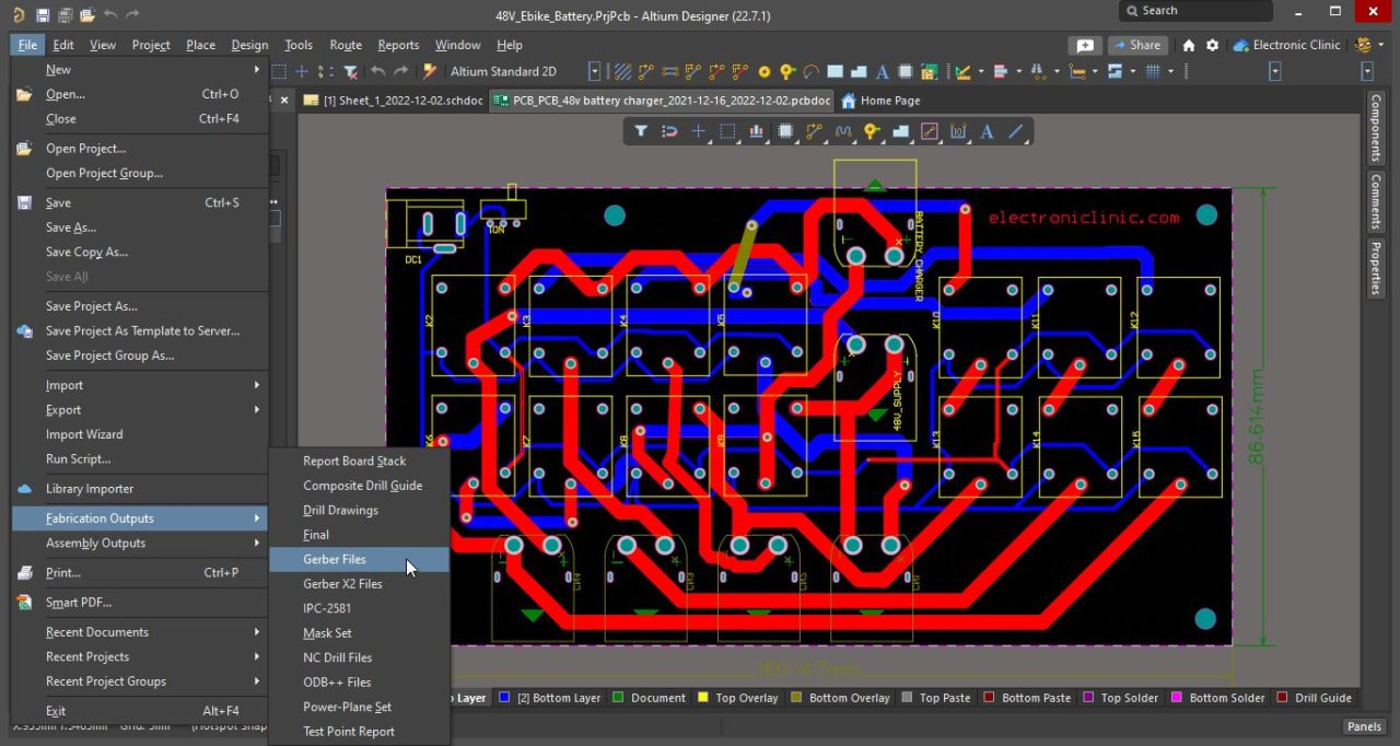
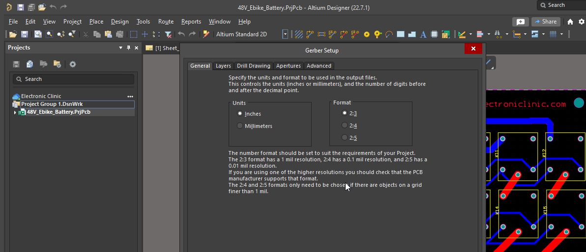
On the units tab select Inches and on the Format tab select 2:3.
Then click on the Layers tab, by default no layers are selected, so click on the Plot Layers and select Used On.

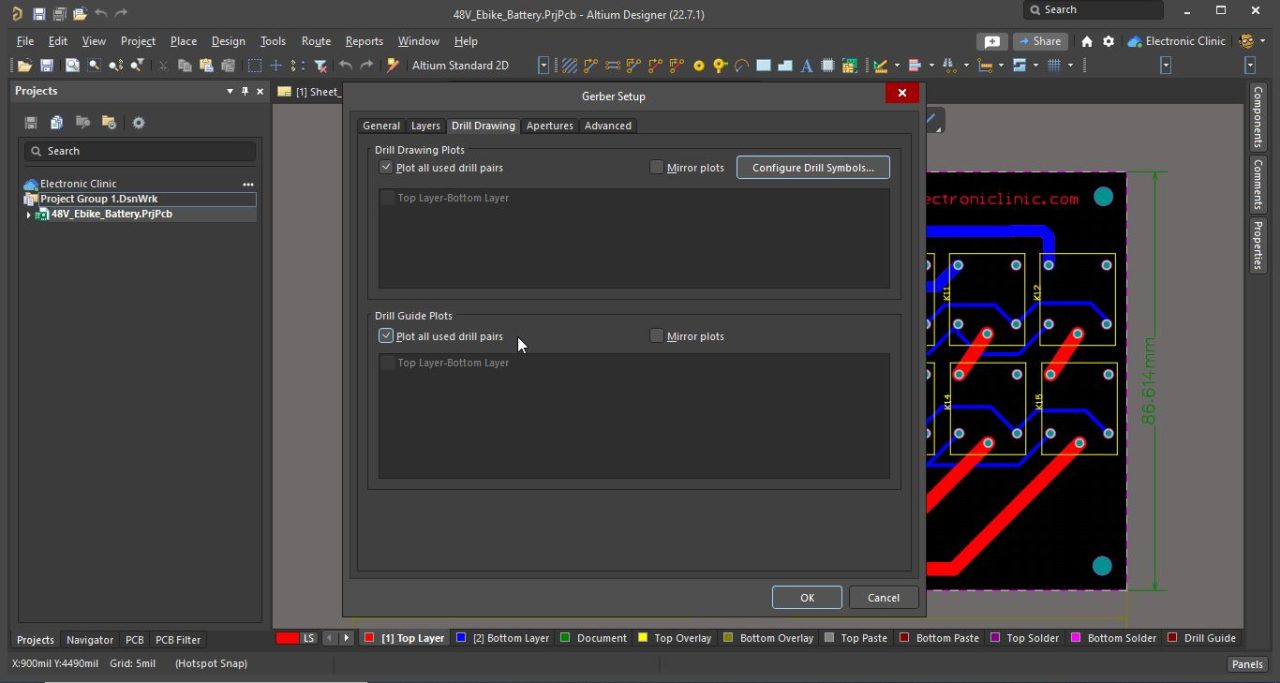
Then click on the Drill Drawing tab and select Plot all used drill pairs in both sections.
Finally, click on the Ok button to generate the Gerber files.
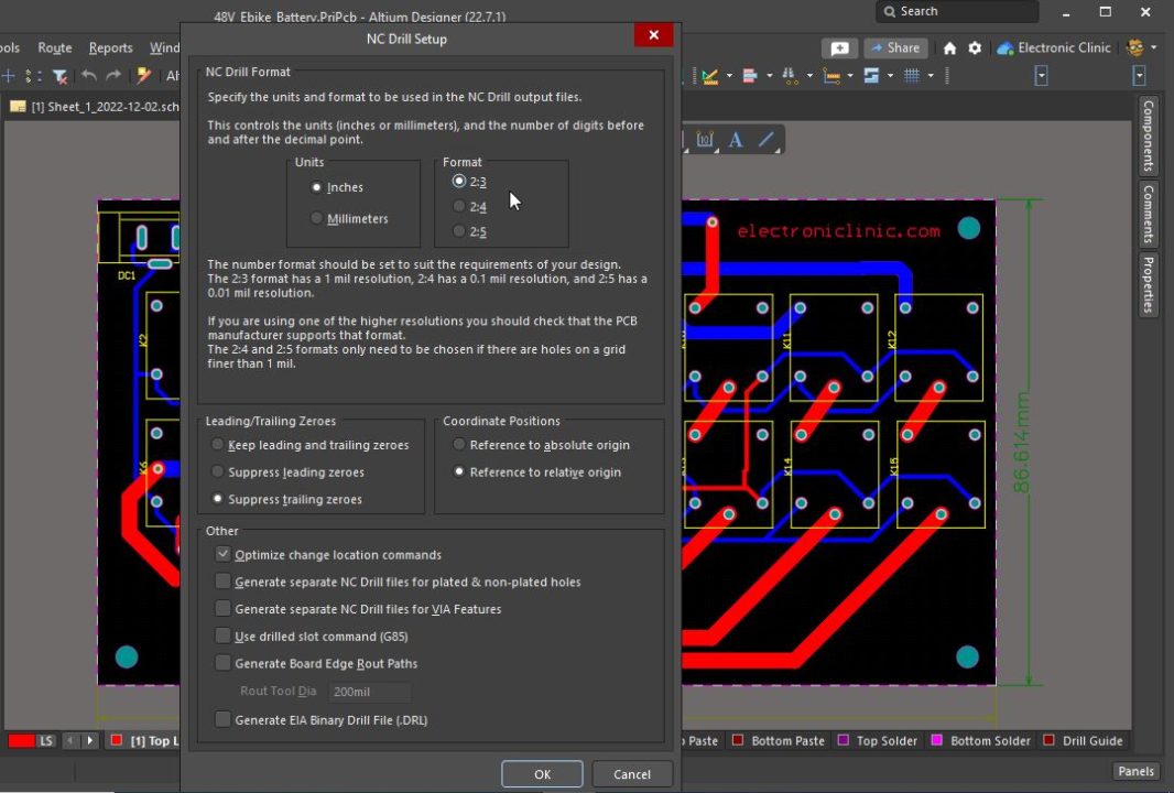
Next, you will also need to generate the NC drill files. For this go to the File Menu and then to Fabrication Outputs and select NC Drill Files.
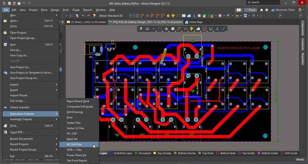
Select inches and Format as 2:3. Then click on the OK button to generate the NC Drill Files.
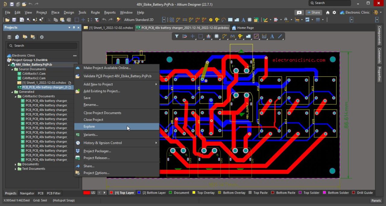
Now, I have the PCB Gerber files and the NC Drill Files. Right click on the project name and select explore this will open the project folder.
Open the Project Outputs folder, now, these are the output files that we need to send to the PCB manufacturing company.
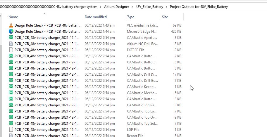
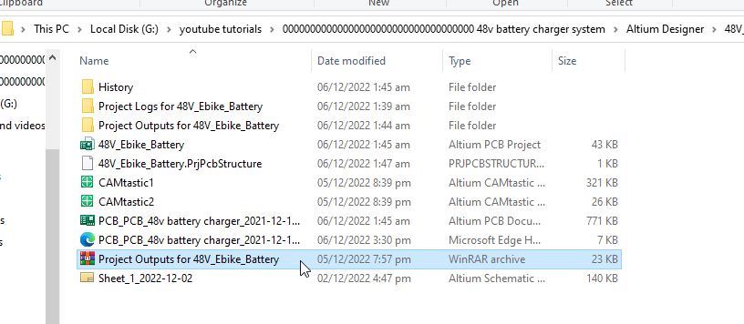
Convert your Project Outputs folder to WinRAR before you send it to the PCB manufacturing company. As you can see in the image below.
Online Order Placement on JLCPCB:
For the Online order placement I am going to open the JLCPCB official website.They offer extremely cheap prices, you only need to pay 2 dollars for 1 and 2 layers PCBs of 100x100mm size.

For the same price, you can also order 4 and 6 layers PCBs of 50x50mm size. 5 PCBs for only 2 dollars it’s quite affordable. Besides this JLCPCB also offers PCB Assembly and 3D Printing Services. Anyway, drag and drop the PCB Gerber files WinRAR folder or Click on the Add Gerber File Button.

It automatically detects the number of layers and the board dimensions. Select the number of PCBs you want to order, you can change other details as per your requirement, in my case I am going to change the PCB color and everything else I will leave to their default values.Now, I am going to click on Save to Cart button.
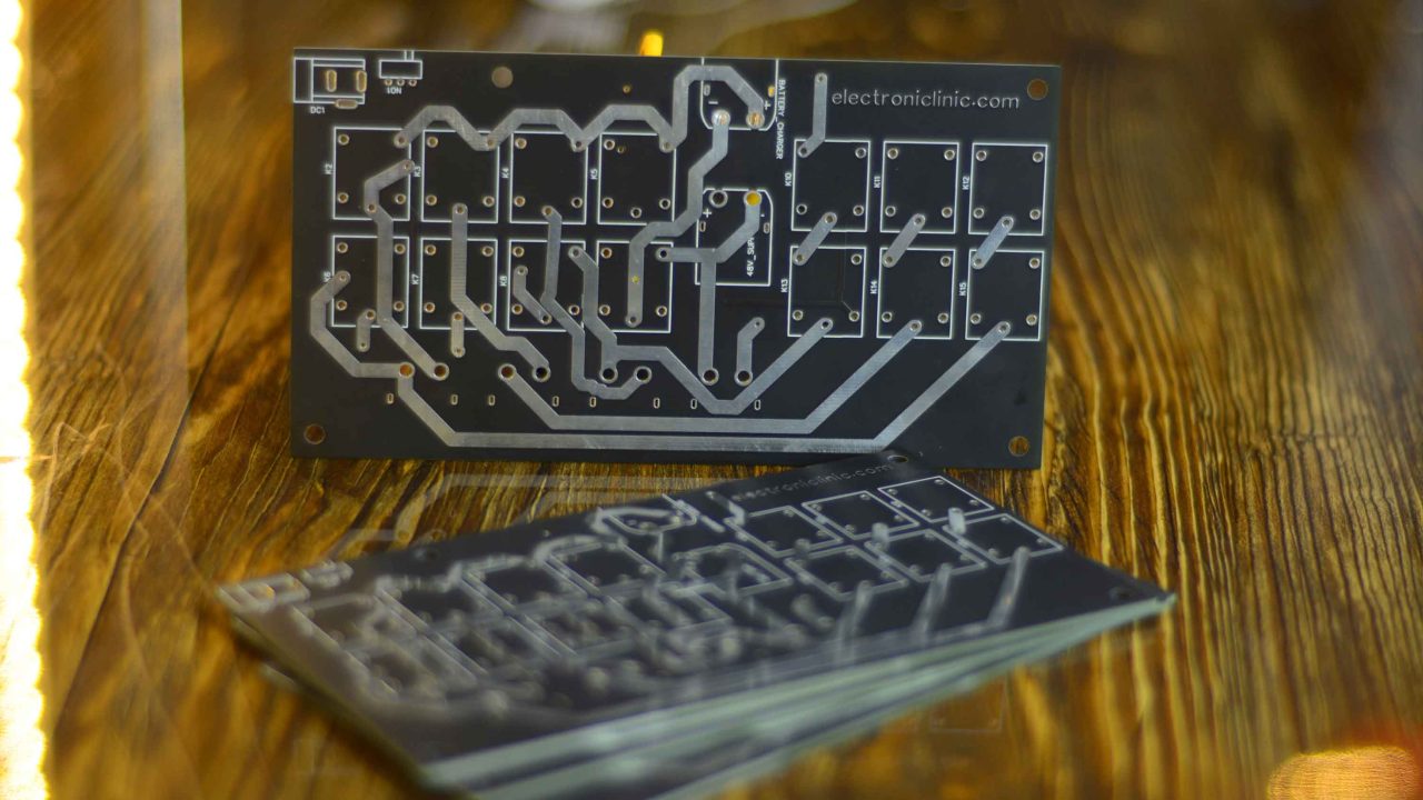
These are the PCBs I received from JLCPCB. As you can see the quality is really great. The silkscreen is quite clear and the Black Solder mask looks amazing.
The components placement and soldering:
For the components placement and soldering watch the video tutorial on my YouTube channel Electronic Clinic or click on the link given at the end of this article. For the soldering I used the ATETool AE689 Soldering Station.
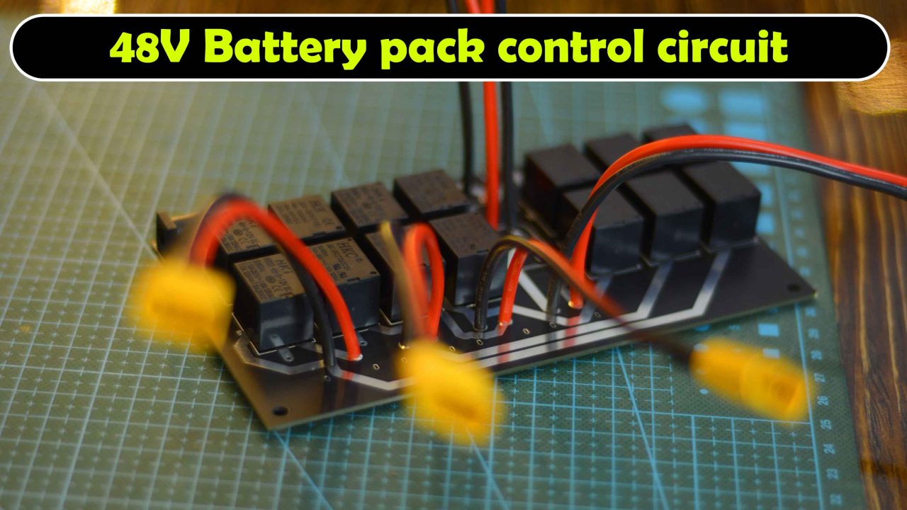
After completing the soldering, I double-checked all the connections using my Andonstar digital microscope. Anyway, you can see I am done with the soldering and as you can see I have also soldered all the 6 XT60 connectors. Now, I am going to connect a 12V adaptor to check if all the relays are working. Great! by turning ON and turning OFF the switch I am able to control all the relays.
Practical Testing:
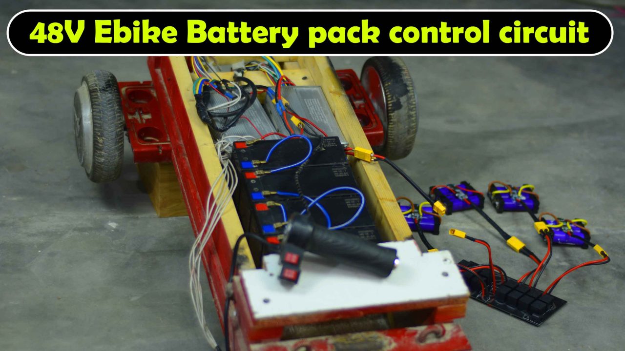
The 500 watts Brushless DC motor controllers wiring I have already explained in my previous article on the Trike Electric Scooter. I am using the same 500 watts controllers, the same throttle handle, and the same Hoverboard motors. The only difference is, this time I am using a 48V Lithium Ion Battery Pack. So, let’s go ahead turn on the switch, and start controlling the motors.
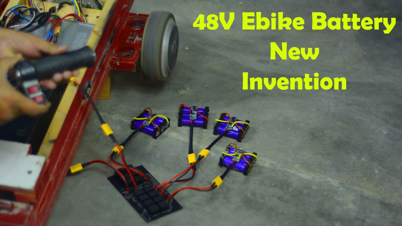
This is simply amazing. I just built myself the cheapest 48V battery pack using low-cost 3S BMS modules. And I can charge this 48V battery pack using a 12V adaptor or a Solar Panel. And one more thing, if you want more current and more backup time then you can connect multiple lithium Ion batteries in parallel. So, that’s all for now.
Watch Video Tutorial:
Discover more from Electronic Clinic
Subscribe to get the latest posts sent to your email.


Hello, I saw your project and I liked it very much, thank you very much for sharing it with people; I have a request from you, it is very simple for you but I could not do it. If you have the circuit diagram of the 6 battery, 12 volt and 72 volt version of this circuit, I would be grateful if you could share it with me.