Arduino GSM Module based Home Automation, Sim900A GSM module
Last Updated on August 16, 2024 by Engr. Shahzada Fahad
Table of Contents
Arduino GSM Module based Home Automation:
Arduino GSM Module based Home Automation, Sim900A GSM module- In today’s article, we are going to make the World’s most secured GSM based Home Automation system using Arduino and Sim900a GSM Module. You can use Arduino Nano or Arduino Uno.

If I use a simple command like this then anyone can control the home appliances or other highly sensitive loads using their cell phones. Because, there is no check who is sending the control command. An automation system like this is useless if it has no security.
So, I came up with an idea of adding a password in the control command.
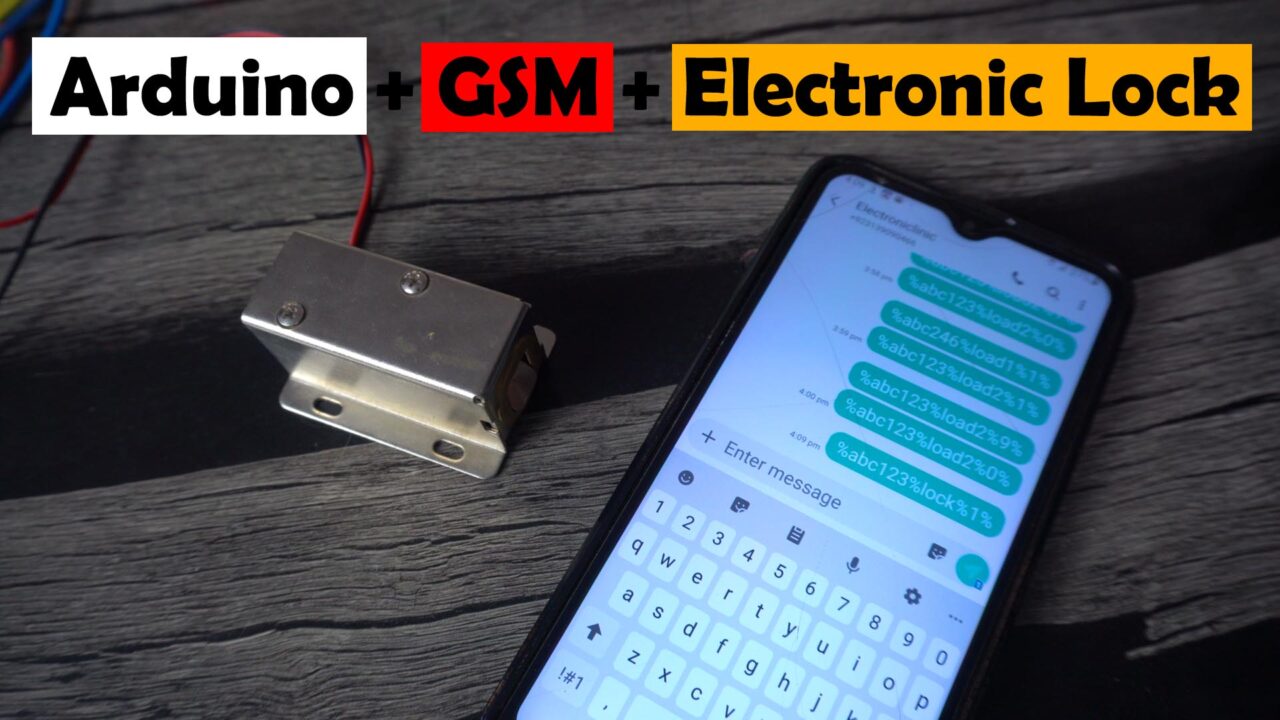
This password can consist of letters, numbers, and special characters. Without a password, nobody would be able to control anything. Because, each time you want to Turn On or Turn OFF a specific load, you will have to enter the password. You can set an extremely strong password and then nobody would be able to control anything. This is the type of GSM based Home Automation that you can totally rely on. Let me demonstrate this for you.
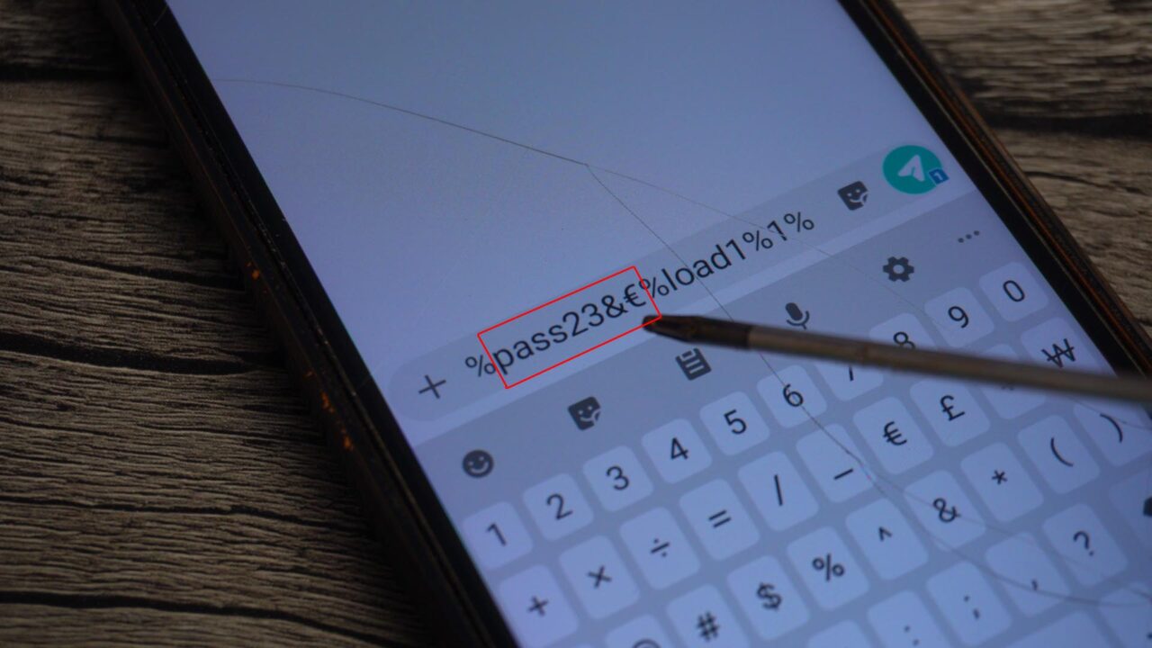
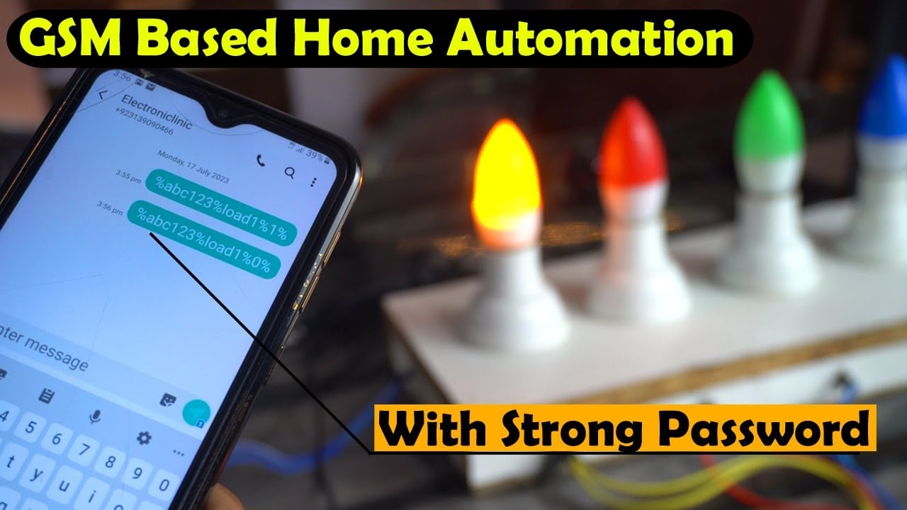
For demonstration purposes, I have selected abc123 as the password, then I selected the load, and then 1 or 0 as a control signal to Turn ON or Turn OFF that load.
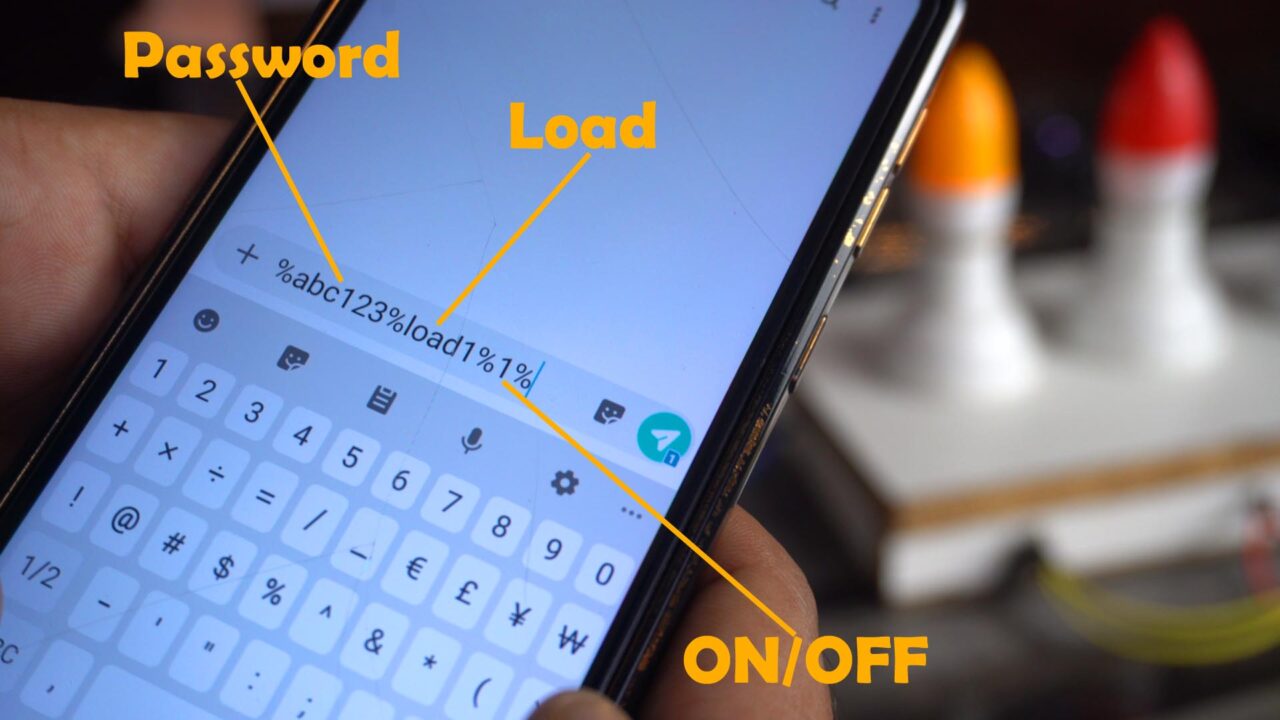
You might have noticed I used percentage sign; I am doing this because when the Arduino receives this message. Then the Arduino can easily split this message using % sign as the delimiter. Anyway, the message is ready, and I am going to send it to the Arduino.

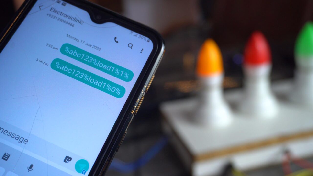
This is amazing, isn’t it?
Now, to turn OFF the same load, I will have to type the same control command but this time I am going to send 0 as the control signal to turn OFF the Load1.
The same way, I can control Load2 and let me also tell, instead of writing load1 and load2, you can also write the load names, bulb1, bulb2, etc. And if I am going to type a wrong password, nothing is going to happen.

I also have this Electronic Door Lock connected to the Arduino. And to control this Lock I am using the same password, but this time instead of using load as the name, I am using the name lock, and 1 or 0 to open or close the Electronic Door Lock.
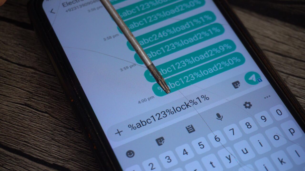
Anyway, I am going to send this message, and let’s see if it’s going to open the Door Lock.
Great, I am also able to control the Electronic Lock. Now, you can also build yourself the mostly highly secured Locker. There are more than a million ways you can use this idea. I am sure by now, you might have got an idea of how does this system work. So, without any further delay let’s get started!!!
Amazon Links:
Arduino Nano USB-C Type (Recommended)
*Disclosure: These are affiliate links. As an Amazon Associate I earn from qualifying purchases.
Sim900a GSM Module:
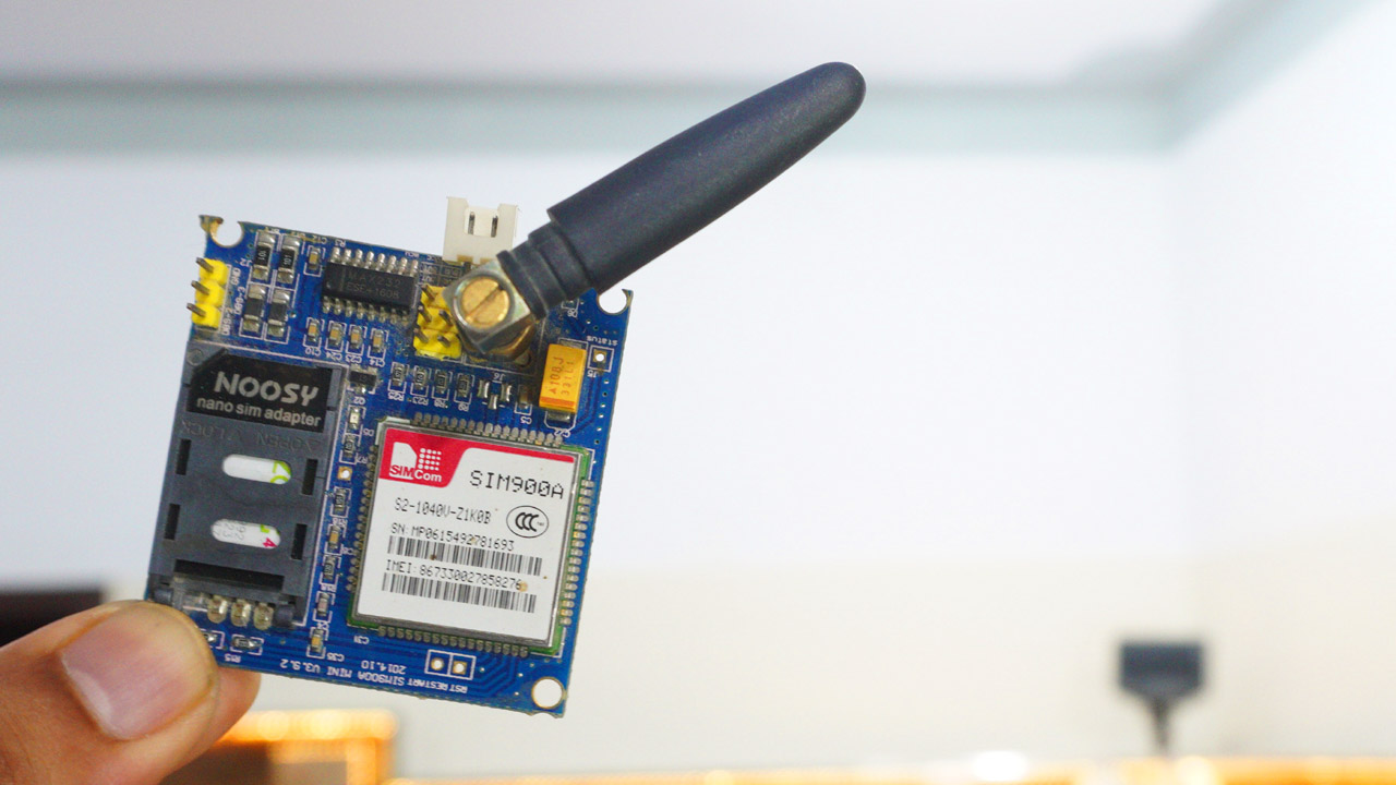
This is the GSM Sim900A mini Module. The first thing that you will notice about this GSM module is that, it has no onboard voltage regulator, so be very careful while applying the voltage; Because voltages greater than 5 volts can easily damage this module. Ideal voltage for this GSM module is 4.7v but you can easily power up this GSM Sim900A module using a 5v and 2A adaptor. if you don’t have a 5v adaptor then you can make yourself power 5V and 3A power supply. I have a detailed article on how to build yourself a 5V and 3A power supply.
There are a few things that I really like about this GSM sim900A module which are
This is the cheapest GSM module available on the Market.
Another cool thing is, it can be easily interfaced with 5V supported controller boards like Arduino Uno, Arduino mega, Arduino Nano etc and also with 3.3v controller boards like Nodemcu ESP8266 Wifi Module and ESP32 etc. The GSM Sim900A module interfacing with Nodemcu ESP8266 and ESP32, I have already explained in my previous videos.
Anyway, I have also a detailed article on the GSM Sim900a module explaining its
Key features
Functional diagram
Pins description
Its applications
How to use it
Its pinout and AT commands.
Now, let’s go ahead and take a look at the circuit diagram.
Arduino GSM Based Home Automation Circuit:
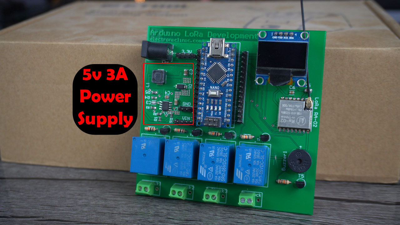
As usual, I am using my Arduino Nano and LoRa based development board. This development board has the advantage of having this 5V and 3A power supply which is more than enough to power up the Arduino and the GSM module.
This development board also has 5V SPDT type relays. So, this development board is ideal for testing this project. And for now, forget about the onboard LoRa module and the 5V Buzzer. Only concentrate on the connections I am about to explain.
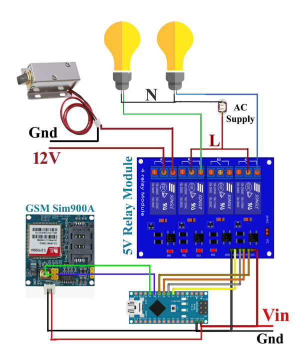
Connect the power supply pins of the GSM Sim900a module to the regulated 5v and 3A power supply. The 5V and GND wires from the 5V and 3A power supply are connected to the Arduino Vin and Gnd pins.

Connect the GSM module TXD 5V pin to the Arduino digital pin D9 and connect the RXD 5V pin to the Arduino digital pin D10.
The 4 channel relay module connected to the Arduino digital pins 4, 5, 6, and 7. And if you want to make your own relay module then you can follow the circuit diagram given below.
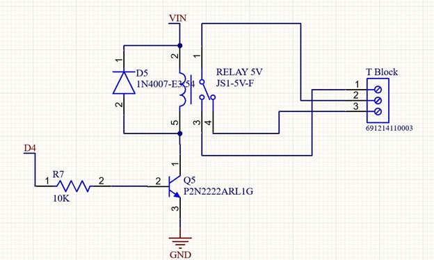
You can also read my article on different types of relays and how to use them.
So, that’s all about the connections. Now, let’s go ahead and take a look at the programming.
Altium Designer, Altium 365, & Octopart:
Altium Designer is the world’s most trusted PCB design system. Altium Designer enables engineers to effortlessly connect with every facet of the electronics design process. Over 35 years of innovation and development focused on a truly unified design environment makes it the most widely used PCB design solution. With Altium Designer you can create PCB designs with an intuitive and powerful interface that connects you to every aspect of the electronics design process. Route it your way through any angle, tune for the delay, Push, Slide, and Walkaround faster than ever.
Easily work together with your mechanical team and forget about the days of swapping design files. Every design change stays in sync between Altium Designer and SOLIDWORKS, PTC Creo, Autodesk Inventor, Autodesk Fusion 360, or Siemens NX*.
Interact and collaborate with mechanical designers like never before in a photo-realistic, 3D design environment.
One of the best things about Altium Designer is that you can share your designs with your team members using Altium 365. They can check your design, leave comments, and if there are any issues, they can fix them from anywhere in the world. Altium Designer also uses the world’s fastest components search engine, Octopart, so you won’t have any difficulty in searching for components.
Altium Designer, Altium 365, and Octopart—unleashes the full potential of electronics design by seamlessly integrating design tools, collaboration platforms, and component databases. Together, they offer engineers a comprehensive and synchronized experience, leading to improved productivity, reduced errors, and accelerated innovation in the world of electronics design.
Arduino GSM Based Home Automation Programming:
|
1 2 3 4 5 6 7 8 9 10 11 12 13 14 15 16 17 18 19 20 21 22 23 24 25 26 27 28 29 30 31 32 33 34 35 36 37 38 39 40 41 42 43 44 45 46 47 48 49 50 51 52 53 54 55 56 57 58 59 60 61 62 63 64 65 66 67 68 69 70 71 72 73 74 75 76 77 78 79 80 81 82 83 84 85 86 87 88 89 90 91 92 93 94 95 96 97 98 99 100 101 102 103 104 105 |
#include <SoftwareSerial.h> SoftwareSerial SIM900(9, 10); // TXpin=9 RXpin=10 int relay1=4; int relay2=5; int relay3=6; int relay4=7; String passcode="abc123"; String incoming = ""; void setup() { Serial.begin(9600); pinMode(relay1,OUTPUT); pinMode(relay2,OUTPUT); pinMode(relay3,OUTPUT); pinMode(relay4,OUTPUT); SIM900.begin(9600); // original 19200 randomSeed(analogRead(0)); SIM900.print("AT+CMGF=1\r"); // set SMS mode to text delay(1000); SIM900.print("AT+CNMI=2,2,0,0,0\r"); // blurt out contents of new SMS upon receipt to the GSM shield's serial out delay(1000); SIM900.println("AT+CMGD=1,4"); // delete all SMS delay(5000); Serial.println("Ready..."); } void loop() { if(SIM900.available() >0) { incoming=SIM900.readString(); Serial.println(incoming); String fulldata = getValue(incoming, '%', 0); String password = getValue(incoming, '%', 1); //contains password String load= getValue(incoming, '%', 2); //contains load number String loadstatus= getValue(incoming, '%', 3);// contains on and off state Serial.print("value 1: "); Serial.println(password); Serial.print("value 2: "); Serial.println(load); Serial.print("value 3: "); Serial.println(loadstatus); int loadvalue = loadstatus.toInt(); if((password==passcode)&&(load=="load1")&&(loadvalue==1)) { digitalWrite(relay1,HIGH); } else if((password==passcode)&&(load=="load1")&&(loadvalue==0)) { digitalWrite(relay1,LOW); } else if((password==passcode)&&(load=="load2")&&(loadvalue==1)) { digitalWrite(relay2,HIGH); } else if((password==passcode)&&(load=="load2")&&(loadvalue==0)) { digitalWrite(relay2,LOW); } else if((password==passcode)&&(load=="load3")&&(loadvalue==1)) { digitalWrite(relay3,HIGH); } else if((password==passcode)&&(load=="load3")&&(loadvalue==0)) { digitalWrite(relay3,LOW); } else if((password==passcode)&&(load=="lock")&&(loadvalue==1)) { digitalWrite(relay4,HIGH); } else if((password==passcode)&&(load=="lock")&&(loadvalue==0)) { digitalWrite(relay4,LOW); } delay(20); } } String getValue(String data, char separator, int index) { int found = 0; int strIndex[] = { 0, -1 }; int maxIndex = data.length() - 1; for (int i = 0; i <= maxIndex && found <= index; i++) { if (data.charAt(i) == separator || i == maxIndex) { found++; strIndex[0] = strIndex[1] + 1; strIndex[1] = (i == maxIndex) ? i+1 : i; } } return found > index ? data.substring(strIndex[0], strIndex[1]) : ""; } |
I started off by adding the SoftwareSerial.h header file. With the help of this library I can defined multiple serial ports. As you can see using the SoftwareSerial I have defined another serial port using the Arduino pins 9 and 10. I could also connect the GSM module to the Arduino default Serial port, but I used it for the debugging purposes.
4 relays are connected to the Arduino pins 4, 5, 6, and 7.
I also defined a variable passcode of the type String, so that I can use a combination of letters, numbers, and characters. So, my password is “abc123”. If I want to change my password then I can simply change this passcode over here.
I also defined a variable for storing the message.
Code in the void setup() function is exactly the same, as used in my previous GSM based security system. So, let’s go to the loop() function.
We simply check if a message is received then store the entire string message in the variable incoming, and then using the % sign as the delimiter we split the message, and store the corresponding values in variables password, load, and loadstatus.
And then I have defined multiple conditions to turn ON and turn OFF the desired loads.
The getValue() function is used to split the message using any character as the delimiter. So, that’s all about the programming.
For the step by step explanation watch the video tutorial and don’t forget to like, share, and subscribe.
Watch Video Tutorial:
Discover more from Electronic Clinic
Subscribe to get the latest posts sent to your email.


