ESP8266 Led Brightness control using Blynk and Arduino IoT Cloud
Last Updated on September 15, 2024 by Engr. Shahzada Fahad
Table of Contents
ESP8266 LED Brightness Control:
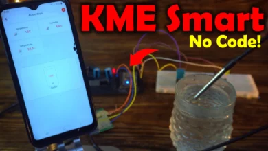
ESP8266 Led Brightness control using Blynk and Arduino IoT Cloud- In this article, you will learn how to control the brightness of LED using the Blynk application and Arduino IoT Cloud. First we will do it using the Blynk application and then we will do it with it using the Arduino IoT cloud. Controlling the Brightness of LED! Seriously? You may think of it as a very basic project, but trust me, once you learn how to control the Led brightness then you can control the speed of anything e.g speed of a DC motor, stepper motor, brushless motor, etc. Since we are using ESP8266 Nodemcu module with Blynk and Arduino IoT Cloud so we can control the LED brightness from anywhere in the world. The reason, I decided to start with the LED is because LEDs can be easily arranged, and moreover, I don’t want to complicate things.
Note: this old version of the Blynk app is no more functional. For the blynk mobile App setup and Blynk.cloud dashboard setup ready my article on the New Blynk V2.0. In this article I have explained how to migrate your projects from Blynk 1.0 to the new Blynk V2.0. You can also watch the video.
Amazon Links:
Disclosure: These are affiliate links. As an Amazon Associate I earn from qualifying purchases.
Led interfacing with ESP8266 Nodemcu:
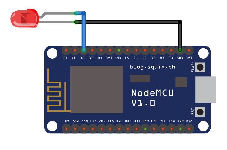
Now to make the circuit we will perform the following steps:
- Connect the anode of the led which is the positive terminal of the led with the digital pin D2. We can also use the built-in led of the NodeMCU which is D0.
- Connect the cathode of the led which is the negative terminal of the led with the ground.
- It’s good to use a 330-ohm current limiting resistor with any of the two legs of the LED.
Designing Blynk app for controlling LED brightness:
First of all we will install the Blynk app in the mobile if it is not installed. Once you have downloaded and installed the Blynk application; then you can open the Blynk application.
Now click on the New Project

After clicking on the New project we will select the name of the new project which is “Led control” and in the device select the NodeMCU and in the connection type select the Wi-Fi and click on the create.

When you click on the Create button an authentication token will be sent on your registered email ide.

Now after that we will add the slider we can select the horizontal or vertical slider. So we will select the horizontal slider and set its dimensions.

Now we will add the gauge; again go to the widget box and select the gauge.

Insert the gauge.
Now click on the slider and select the pin which you are using as we are using the virtual pin so we will select the virtual pin V0 and click on the OK.

Then set its range from 0 to 255.

Then select the gauge and select the pin which is virtual pin V1.

Now again set its value from 0 to 255

In push select 1 second

Now our app is completed

ESP8266 LED brightness control code:
One thing to remember while writing the code the SSID is the name of the Wi-Fi connection or router and pass is the password of the Wi-Fi router.
Complete code:
|
1 2 3 4 5 6 7 8 9 10 11 12 13 14 15 16 17 18 19 20 21 22 23 24 25 26 27 28 29 30 31 32 33 34 |
#define BLYNK_PRINT Serial #include <ESP8266WiFi.h> #include <BlynkSimpleEsp8266.h> // You should get Auth Token in the Blynk App. // Go to the Project Settings (nut icon). char auth[] = "2ro_L9gmugpg6FfbtZ4Il5QMxJqlHY34"; // Your WiFi credentials. // Set password to "" for open networks. char ssid[] = "AndroidAP3DEC"; char pass[] = "123456"; void setup() { // Debug console Serial.begin(9600); Blynk.begin(auth, ssid, pass); // You can also specify server: //Blynk.begin(auth, ssid, pass, "blynk-cloud.com", 80); //Blynk.begin(auth, ssid, pass, IPAddress(192,168,1,100), 8080); } void loop() { Blynk.run(); } BLYNK_WRITE(V0) { int pinValue = param.asInt(); // assigning incoming value from pin V1 to a variable // You can also use: // String i = param.asStr(); // double d = param.asDouble(); analogWrite(D0, pinValue); Blynk.virtualWrite(V1, pinValue); Serial.print("V0 Slider value is: "); Serial.println(pinValue); } |
Then upload the code to the NodeMCU ESP8266, open the Blynk application in the Mobile, and by changing the value of the slider you will be able to change the brightness of the led.
LED brightness control using Arduino IoT Cloud:
Now we will control the same LED brightness using the Arduino IoT cloud. So in order to control the led we will first create the application; so we will perform the following steps:
First we will create the variable of integer type with the name led

Now the led variable is created and now we will configure the device

Now, we will select the device so click on the select device and then select the third party device and in the select type device we will select the ESP8266 and select NodeMCU 1.0 and click on the continue button.

Then we will give a name to the device, in our case we are giving the name My_Node_MCU and click on the next button.

Now in order to make the device ready to use we will click on the download button and save the security id and secret key which will be used in network connection. If its hard for you to follow the steps then you can read my getting started article on the Arduino IoT Cloud.
After that we will configure the network; so click on the network button to give the SSID which is the name of the Wifi which we are using and give the password and paste the secret key which we have copied in the add device and click on the save button.
Designing the dashboard on Arduino IoT Cloud:
Now we will click on the dashboard and click on the add button to insert the slider and link it with the led variable.

Then insert the gauge and link it with led button.

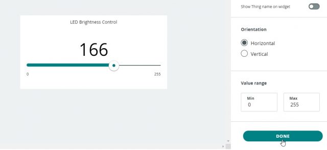
Then we will set the limit for slider and gauge just click on the slider and write the minimum and maximum limits which are:

Finally, our Arduino IoT Cloud Dashboard is ready.
ESP8266 LED Brightness Control Arduino IoT Cloud Code:
Now in order to upload the code we will click on the sketch to write the code
|
1 2 3 4 5 6 7 8 9 10 11 12 13 14 15 16 17 18 19 20 21 22 23 24 25 26 27 28 29 30 31 32 33 34 35 36 37 38 39 40 41 42 43 44 45 46 47 48 49 50 51 52 53 54 55 56 57 58 |
/* Sketch generated by the Arduino IoT Cloud Thing "Untitled" https://create.arduino.cc/cloud/things/cadb10bb-abca-4fc1-a5bf-c0b9c97d386a Arduino IoT Cloud Variables description The following variables are automatically generated and updated when changes are made to the Thing int led; Variables which are marked as READ/WRITE in the Cloud Thing will also have functions which are called when their values are changed from the Dashboard. These functions are generated with the Thing and added at the end of this sketch. */ #include "thingProperties.h" #define LED D0 void setup() { // Initialize serial and wait for port to open: Serial.begin(9600); // This delay gives the chance to wait for a Serial Monitor without blocking if none is found delay(1500); pinMode(LED, OUTPUT); // LED pin as output. // Defined in thingProperties.h initProperties(); // Connect to Arduino IoT Cloud ArduinoCloud.begin(ArduinoIoTPreferredConnection); /* The following function allows you to obtain more information related to the state of network and IoT Cloud connection and errors the higher number the more granular information you’ll get. The default is 0 (only errors). Maximum is 4 */ setDebugMessageLevel(2); ArduinoCloud.printDebugInfo(); } void loop() { ArduinoCloud.update(); // Your code here } void onLedChange() { // Do something // this command will be used to control the led through slider analogWrite(D0,led); Serial.print("Slider value is: "); Serial.println(led); } |
To upload the code, you will have to select the board type and the port number, I have already talked about this in my previous articles on the Arduino IoT Cloud. So, once you have uploaded the code then you can use the Slider to control the brightness of LED.
Discover more from Electronic Clinic
Subscribe to get the latest posts sent to your email.