Exclusive OR gate (XOR) Working Principle & Circuit Diagram
Last Updated on September 19, 2022 by Engr. Shahzada Fahad
Table of Contents
Exclusive OR gate (XOR)
The exclusive OR gate is also sometimes known as “any but not all gate” and its represented by XOR in short. Exclusive is a specific type of OR gate. A high or 1 output is received on this gate when inputs are on inter – inverted levels (for example output from a two – input XOR is possible when one of its input is low or on zero level while the other input is high or on level 1). It means that zero output results from the gate at a time when all of its inputs are on the same level (e.g. 00 or 11). In other words, when any one of the inputs being provided on gate is high or 1, the output is high or 1.
The best method to understand operation of a XOR gate is that out of its whole inputs, this gate produces high output by means of odd numbered high inputs (e.g.1, 3, 5 etc.) only, whereas this gate provides low or zero output through its even numbered (2, 4, 6 etc.) high inputs from its entire inputs. (that’s if 1 or 3 inputs are high on the input side, it delivers high output, whereas if 2 or 4 inputs on the input side are high or on level 1, the gate provides zero output). This gate is widely used as a digital comparator in so many digital techniques.
| Output is high when both inputs are at opposite level (i.e. any one input is low and other input is high) |
Or
| Output is low when both inputs are at the same level (i.e. both inputs are low or both inputs are high |
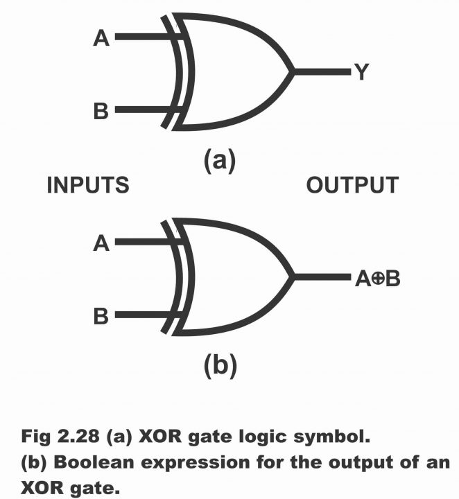
In figure 2.28, the logic or electronic symbol of XOR gate has been depicted. It is evident from the figure that an extra or additional line has been drawn on the input side of the XOR gate, which is a distinct symbol of an exclusive gate.
Figure 2.28 (a). XOR gate logic symbol (b). Boolean expression for the output of an XOR gate
Boolean Expression
This gate operates under following Boolean expression
A XOR B = C
Or
| A ꚛ B = C |
In figure (b), the Boolean expression of XOR gate has been demonstrated on the output side of the gate. There is no difference between the Boolean equations of OR gate and XOR gate, with the only exception that in case of XOR gate, a small circle is made around the (+) sign between A and B, which means exclusive OR (XOR). The circle around + sign is also known as a detector, because output is received from the gate only when both inputs are different.
Truth Table
In figure 2.29, truth table of XOR gate has been represented alongside truth table of OR gate. Towards the right of this table on the output column, output of OR gate has also been given along with output of XOR gate, so that a comparison of both the outputs could be made. The points discussed above can easily be corroborated through study of this truth table. That’s output from this gate is high only when both inputs are mutually on opposite levels (in other words, when first input is low and the other is high, or when the first input is high and other is low, we get high output). This has been demonstrated via lines 2 and 3 as mentioned in the table. However, when both inputs are on the same level (as first and fourth lines of the table), we always get a low output.
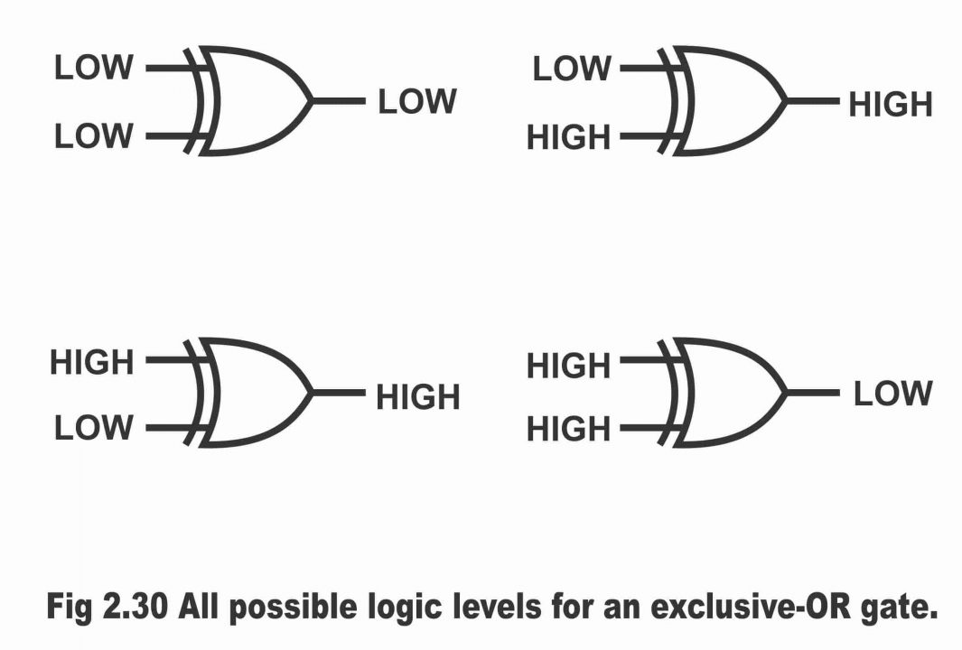
Figure 2.30 – All possible logic levels for an exclusive – OR gate
Previous Topic: Logic NAND Gate Working Principle & Circuit Diagram
Next Topic: Exclusive NOR Gate or XNOR Working Principle & Circuit Diagram
For electronics and programming-related projects visit my YouTube channel.
Discover more from Electronic Clinic
Subscribe to get the latest posts sent to your email.


