How to make Electric Bike Motor Controller using Arduino
Last Updated on August 23, 2024 by Engr. Shahzada Fahad
Electric Bike Motor Controller Description:
In this tutorial, you will learn how to make your own Electric Bike Motor controller using Arduino, mc33151 Mosfet driver, and N-Channel IRF1404 Power Mosfets. After watching this video you will be able to design your own High Power Electric Bike motor controller. In this Tutorial, I am also going to explain why maximum motor drivers get fail. Watch my Video Tutorial in which I used the same Electric Bike Motor Controller, Smart Electric Bike.
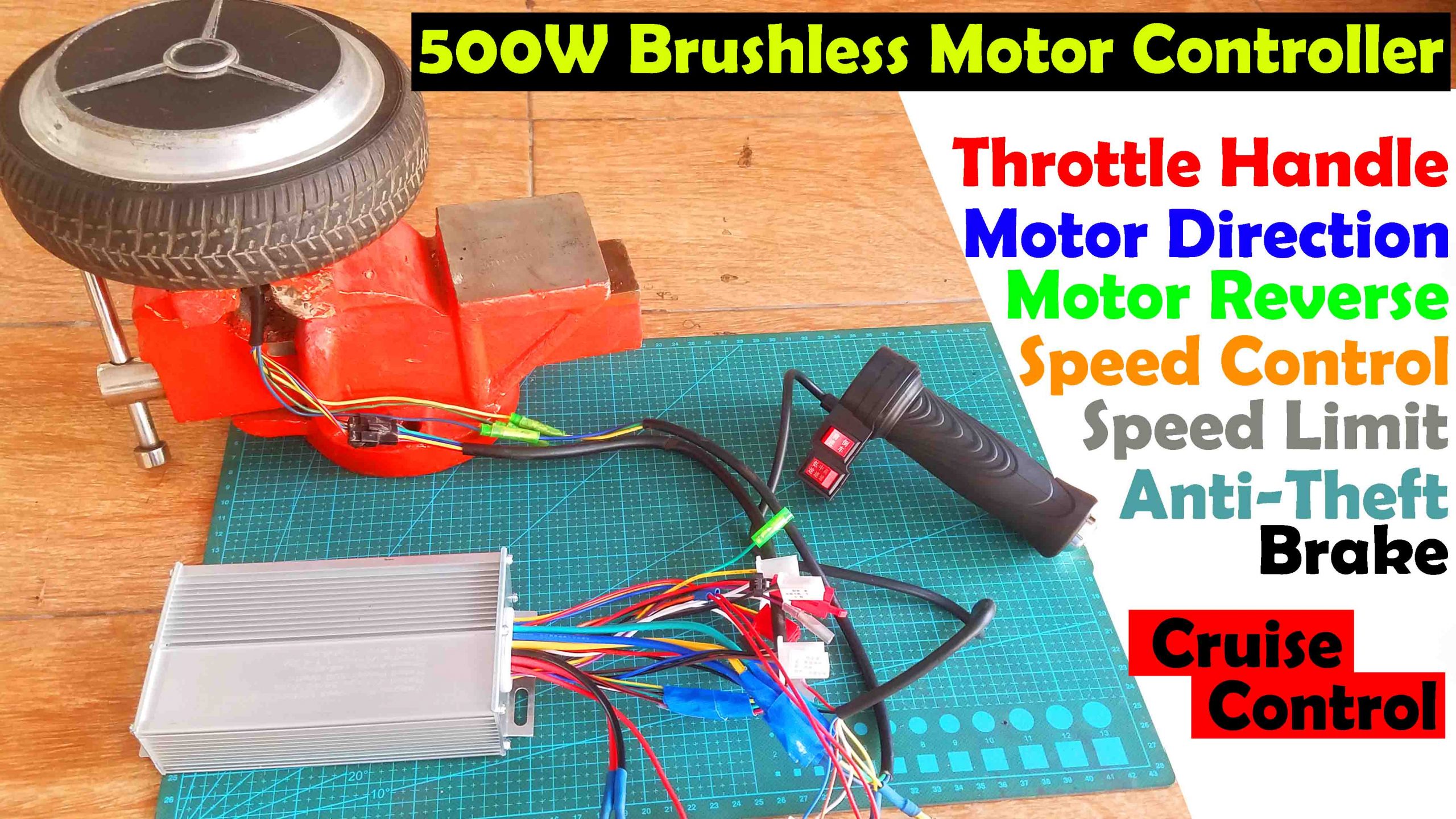
Using only one Mosfet to control a motor is very easy, but when it comes to parallel MOSFETs the things really get complex. So today I am going to practically show you how to use MOSFETs in parallel to control a 24v 500Watt Electric Bike Motor. Without any further delay, let’s get started!!!!!
If in case you want to check my latest work on
Salvage Hoverboard Motors from a dead Hoverboard
500 watts Ebike BLDC Motor Wiring
How to make a Trike Electric Scooter using Hoverboard motors and 500 Watt Motor controllers
Amazon Links:
24v 500 Watt Electric Bike Motor:
IRF1404 N-channel Power MOSFETs:
Disclosure: These are affiliate links. As an Amazon Associate I earn from qualifying purchases.
Why do we think it’s hard to design a High Power Motor Driver?
And spend a lot of money on purchasing the Motor drivers. While in reality, it’s very easy if you follow my instructions you can even make a 1000 watt motor driver or even more. Now let me explain why we get failed when it comes to high power motor drivers. In theory, we studied to handle more current we need to connect the Mosfets drains together and also the Mosfets sources together. But in practice, this is not enough.
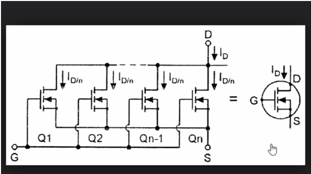
If you search on the Google you will find the same exact thing and it never works. More than 90% of the guys are talking about the same thing and trust me in the begging I have done it and it has never worked. If you follow these connections one Mosfet really gets hot while the other Mosfets stay cool. The purpose of connecting the MOSFETs in parallel is to increase the current handling capability of the driver which is only possible if the current is equally divided among the Mosfets. So with these connections only it’s impossible to use MOSFETs in parallel. Don’t even try these circuits because it will never work.
Let’s make a fully working Motor Driver?
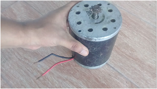
I have this 24v 500 Watt electric bike Motor. To control this motor I am going to use two 1404 N-channel Power MOSFETs in parallel. If you look at the datasheet of the 1404 Mosfet you will find the first leg is the Gate, 2nd one is the Drain and the third one is the Source. Drain to Source voltage is 40 volts. As my Motor is 24volts so this is best for me. If your motor is let’s say 48 volts then you can select any other Mosfet which can handle voltages greater than 40 volts while the rest will remain the same. This Mosfet has a drain current of 202A. this is the Absolute maximum rating when the temperature is 25C. This is really hard to maintain.
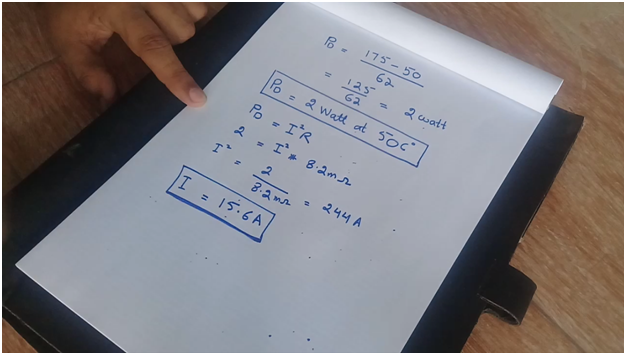
So, after performing my calculation for an extreme ambient temperature of 50C. The calculated value that I got was 15.6 amps, which is not enough to run my 500W electric bike motor. So I decided to use two MOSFETs in parallel. To control these Mosfets I am going to use MC33151. If you study the datasheet of the MC33151 you will find it’s a two-channel MOSFETs driver, which means you can control two Power MOSFETs at the same time and is most commonly used in motor controllers.
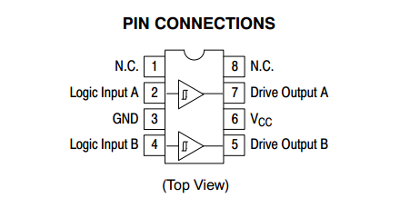
The MC33151 MOSFETs driver has a total of 8 pins. Pin number 1 is not connected, pin number 2 is the logic input A, Pin number 3 is the Ground, Pin number 4 is the logic input B, pin number 5 is Drive output B, pin number 6 is the VCC, pin number 7 is the drive output A and pin number 8 is not connected.
In this tutorial, I am not using any Heat sink with the Mosfets due to the temperature testing, but you must use a large Heat sink. Now let’s have a look at the complete Circuit Diagram.
Electric Bike Motor Controller Circuit Diagram:
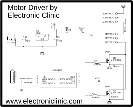
This schematic is designed in the Cadsoft Eagle 9.1.0 version. If you want to learn how to make a schematic and PCB then watch my Tutorial.
The MC33151 library can be downloaded by clicking on the download.
Download MC33151 Library:MC33152
First, let’s start with the Power Supply.
This Power Supply is based on the famous LM7812 voltage regulator. J1 is the female power jack and this is where we connect 12 volts from the battery or solar panel. Two 470uf capacitors are connected at the input and output of the voltage regulator. 1 kilo-ohm resistor is connected in series with the 2.5v led. This is a current limiting resistor. the output of this voltage regulator is connected with the VCC pin of the MC33151 MOSFET driver.
Pin number 2 and pin 4 which are the logic input A and logic input B are connected together and will be connected with the PWM pin of the Arduino or Mega. Pin number 5 and pin number 7 are used to control the MOSFETs. As you can see the Drains are connected together and the sources of both the MOSFETs are also connected together. over here we connect the motor while over here we connect the 24volts. Before making the PCB I tested this circuit on a breadboard…. after I was satisfied with the result, then I designed a PCB, I have already sent my PCB Gerber files to the PCBWay company. But for now, let’s do it on the Vero board. All the connections are 100% as per the circuit diagram already explained.
Soldering:
For Soldering Watch Video Tutorial given at the end.
Electric Bike Motor Controller Programming:
|
1 2 3 4 5 6 7 8 9 10 11 12 13 14 |
int resistor = A0; int PWMV = 3; void setup() { Serial.begin(9600); pinMode(PWMV, OUTPUT); pinMode(resistor, INPUT); } void loop() { int data = analogRead(resistor); data = map(data,0,1023,0,255); analogWrite(PWMV, data); } |
This is a very simple and basic program. A variable resistor is connected with the analog pin A0 of the Arduino. Pin number 3 of the Arduino which is the PWM pin will be used to control both the MOSFETs. The PWMV is set to output while the resistor is set to input. in the void loop function we simply read the variable resistor, then using the map function to limit the value from 0 to 255 and then we finally use the analogWirte function which you are quite familiar with.
I have already uploaded this program, let’s watch this project in action. During the testing, I put some load on the motor to check if both the MOSFETs get hot….while touching the MOSFETs I could feel the same temperature which means that both the MOSFETs are in operation and can divide the current. When MOSFETs are connected in parallel they must share approximately the same amount of current. Before you practically install this Motor driver make sure to use a large heat sink. In a future tutorial, I will implement this circuit on a PCB board and will practically install this in an Electric Bike.
Watch Video Tutorial:
Discover more from Electronic Clinic
Subscribe to get the latest posts sent to your email.


Will this work for a 250w 30v motor?
What’s the speed of the motor
Now do one for a 36V BLDC motor. It’s a lot harder than you think it will be.