IoT Door Sensor Reed Switch based Security System using Nodemcu ESP8266
Last Updated on September 21, 2024 by Engr. Shahzada Fahad
IoT Door Sensor Project Description:
IoT Door Sensor Reed Switch based Security System using Nodemcu ESP8266- In this tutorial; you will learn how to make an IoT based Door Security system using a Magnetic Reed Switch, Nodemcu ESP8266 Wifi Module, and Blynk application. Each time the door is opened or closed a notification message is sent to the desired application. When the door is closed the right side LED is turned ON and when the door is opened the left side LED is turned ON.
The Nodemcu ESP8266 Wifi Module programming is done in such a way that it sends only one notification message when the door is opened or the door is closed, which became possible by using a flag in the programming. So, in this tutorial, you will also learn how to use a flag in the programming to stop the unnecessary repetition of code.
Even if this application is running in the background still you will be able to receive the notifications. This project can be used for monitoring the lockers, Cupboards, garage door, and this project can also be used in advanced level projects like monitoring the Car bonnet, Doors, etc. In fact, this project can be used anywhere where you need the magnetic Reed Switch. We can also name this project as the IoT Reed Switch.
Note: For the practical demonstration watch video Tutorial give at the end of this article.
In this tutorial, we will cover
- Complete Circuit Diagram
- Interfacing
- Blynk Application designing
- Program explanation and finally
- Testing
Without any further delay let’s get started!!!
Amazon Links:
Please Note: these are affiliate links. I may make a commission if you buy the components through these links. I would appreciate your support in this way!
Circuit Diagram of the IoT Door Sensor “Reed Switch”:

This Schematic is designed in CadeSoft Eagle 9.1.0 version. If you want to learn how to make a schematic and PCB, then watch my video tutorial.
First of all, let’s start with the Power Supply which is used to power up the Nodemcu Module. This Power Supply is based on the famous LM7805 voltage regulator. J1 is the Female Power Jack and this is where we connect a 12v adaptor, battery, or a Solar panel. Two 470uf decoupling capacitors are connected at the input and output sides of the 7805 voltage regulator. A 330-ohm resistor is connected in series with a 2.5v LED. This is a current limiting resistor. The output of the voltage regulator is connected with the Vin pin of the Nodemcu ESP8266 Wifi module and the GND of the power supply is also connected with the ground of the Nodemcu Module.
A magnetic Reed Switch is connected in series with a 10k resistor. This is a Pull Up resistor. When the two contacts of the Reed Switch are open it gives 3 volts to the digital pin D0 of the Nodemcu Module. On the other hand, when the two contacts of the Magnetic Reed Switch are closed, then GND is given as a signal to the digital pin D0 of the Nodemcu Module.
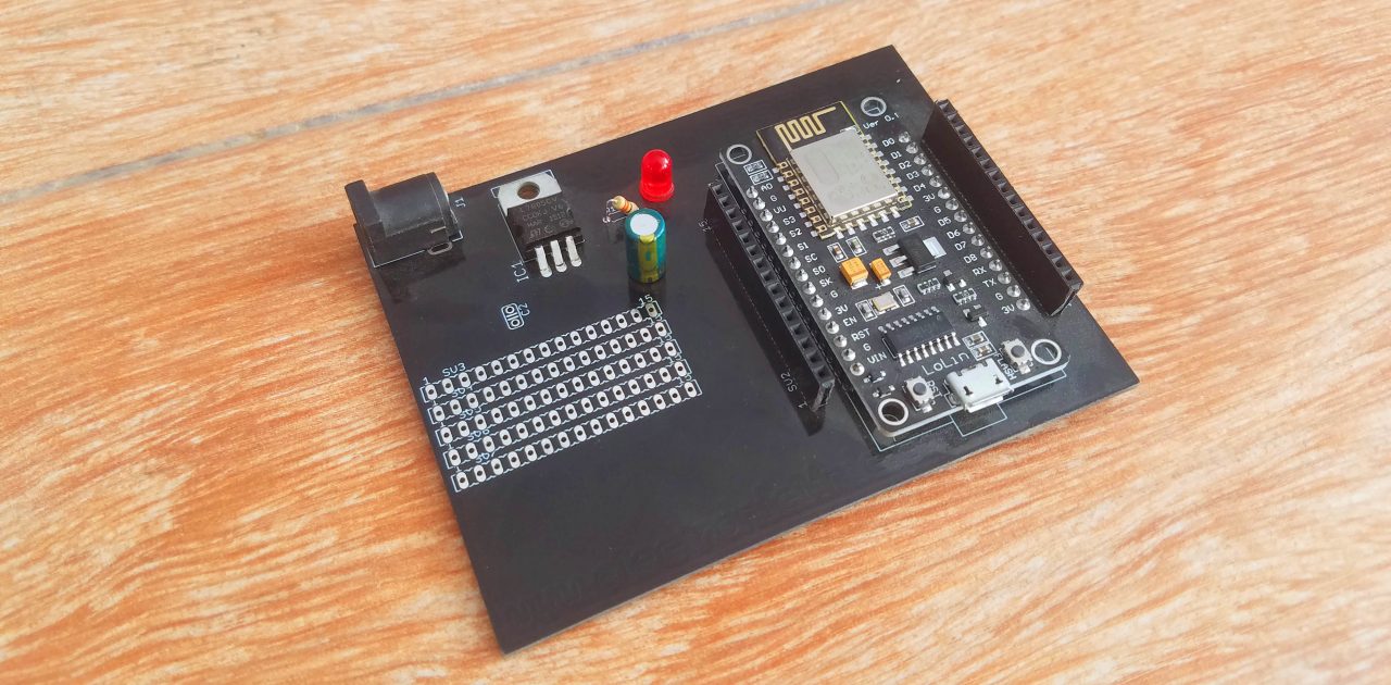
This is the Final Nodemcu Power Supply Circuit board after soldering, the PCB designing, online order placement, and soldering are already explained in my previous tutorial. The link is given in the related projects section.

For the easy interfacing, I am going to fix the Magnetic Reed Switch and the 10k resistor on the Vero Board. Step by Step soldering is explained in the video Tutorial available at the end of this article.
Reed Switch Interfacing with Nodemcu ESP8266:

As you can see, a 10k resistor is connected in series with the Normally Open type Magnetic Reed Switch. The upper leg of the resistor is connected with the 3 volts while the lower leg of the Magnetic Reed Switch is connected with the GND. A wire from the middle of the 10k resistor and Magnetic Reed Switch is connected with the Digital pin D0 of the Nodemcu Module.

I tested the hardware and once I was satisfied with everything, I fixed the Nodemcu circuit board on the wall. The Reed switch on the door frame and the permanent Magnet on the Door. The Magnet is the movable part while the Reed Switch stays in place.
Note: this old version of the Blynk app is no more functional. For the blynk mobile App setup and Blynk.cloud dashboard setup ready my article on the New Blynk V2.0. In this article I have explained how to migrate your projects from Blynk 1.0 to the new Blynk V2.0. You can also watch the video.
Blynk Application Designing for the IoT Door Sensor:
You can watch a video tutorial give at the end of this article or you can follow the following steps.
- First of all, Open the Blynk application…
- Click on the new project and enter the project name as IoT Door Security …
- Click on the choose device and select Nodemcu…
- Make sure you set the connection type to WIFI…
- Finally, click on the create button, an authentication token will be sent on your email ID which will be then used in the programming. Simply copy and paste it in the programming…
- Now click on the screen and search for the LED and add it…
- Click again on the screen and add another LED…
- Click again on the screen and this time search for the notification widget and add it…
- Click on the first LED set the name as Door Open and select the virtual pin V2…
- Now click on the 2nd LED to set the name as Door Close and select virtual pin V3…
That’s it. Our application is ready, and now let’s discusses the Nodemcu programming.
IoT Door Sensor Nodemcu Programming:
|
1 2 3 4 5 6 7 8 9 10 11 12 13 14 15 16 17 18 19 20 21 22 23 24 25 26 27 28 29 30 31 32 33 34 35 36 37 38 39 40 41 42 43 44 45 46 47 48 49 50 51 52 53 54 55 56 57 58 59 60 61 62 63 64 65 66 67 68 69 70 71 72 |
#define BLYNK_PRINT Serial #include <ESP8266WiFi.h> #include <BlynkSimpleEsp8266.h> #include <SoftwareSerial.h> #include <SimpleTimer.h> char auth[] = "Q73mBD0LcPCXZucsHgScapeYswG4zZki"; // Your WiFi credentials. // Set password to "" for open networks. char ssid[] = "ZONG MBB-E8231-6E63"; char pass[] = "electroniclinic"; SimpleTimer timer; // This function sends Arduino's up time every second to Virtual Pin (1). // In the app, Widget's reading frequency should be set to PUSH. This means // that you define how often to send data to Blynk App. void myTimerEvent() { // You can send any value at any time. // Please don't send more that 10 values per second. Blynk.virtualWrite(V1, millis() / 1000); } int reed_s = D0; // Reed sensor int flag = 0; void setup() { // Debug console Serial.begin(9600); Blynk.begin(auth, ssid, pass); pinMode(reed_s, INPUT_PULLUP); timer.setInterval(1000L,sensorvalue1); } void loop() { Blynk.run(); timer.run(); // Initiates BlynkTimer } void sensorvalue1() { if((digitalRead(reed_s) == LOW) && ( flag == 0 )) { Blynk.virtualWrite(V2,0 ); //turns off the led Blynk.virtualWrite(V3,255 ); // turns on the led Blynk.notify("Door Closed!!!"); flag = 1; } if((digitalRead(reed_s) == HIGH) && ( flag == 1) ) { Blynk.virtualWrite(V2,255 ); // turns on the led Blynk.virtualWrite(V3,0 ); // turns off the led Blynk.notify("Door Opened!!!"); flag = 0; } } |
IoT Door Sensor Program Explanation:
All the libraries used in this project can be downloaded by clicking on the link below.
Download Libraries
If you are using the Nodemcu Module for the first time then I recommend first watch my getting started tutorials on the Nodemcu ESP8266 Wifi Module, which explains how to install the Nodemcu board, how to fix some of the most common errors and how to download the blynk library. Visit my YouTube channel “Electronic Clinic” and search for the Nodemcu playlist.
char auth[] = “Q73mBD0LcPCXZucsHgScapeYswG4zZki”;
This is the authentication token, which was sent via email. I simply copied and paste it over here.
char ssid[] = “ZONG MBB-E8231-6E63”;
char pass[] = “electroniclinic”;
This is the name and password of the wifi router.
void myTimerEvent()
{
// You can send any value at any time.
// Please don’t send more that 10 values per second.
Blynk.virtualWrite(V1, millis() / 1000);
}
This is the same function I have been using in almost all of my IoT based projects based on the Nodemcu module.
int reed_s = D0; // Reed sensor
The Magnetic Reed Sensor is connected with the digital pin D0 of the Nodemcu ESP8266 Wifi Module.
int flag = 0;
The variable flag which is of the type integer is used as the flag.
void setup()
{
// Debug console
Serial.begin(9600);
Blynk.begin(auth, ssid, pass);
pinMode(reed_s, INPUT_PULLUP);
timer.setInterval(1000L,sensorvalue1);
}
In the void setup function I activated the Serial communication using the Serial.begin function and selected 9600 as the baud rate.
The blynk.begin function takes three arguments as the input the authorization, ssid and password.
Then I set the reed sensor as the input.
Sensorvalue1 is a user defined function. this function is called every 1 second.
void loop()
{
Blynk.run();
timer.run(); // Initiates BlynkTimer
}
Then starts the void loop function; inside the void loop function we have only two functions blynk.run and timer.run.
As I said earlier sensorvalue1 is a user defined function. This function has no return type and does not take any arguments as the input.
if((digitalRead(reed_s) == LOW) && ( flag == 0 ))
{
Blynk.virtualWrite(V2,0 ); //turns off the led
Blynk.virtualWrite(V3,255 ); // turns on the led
Blynk.notify(“Door Closed!!!”);
flag = 1;
}
This condition checks if the door is closed and the flag is zero. Then turn off the door open led and turn on the door closed led and send a notification message and finally change the flag status from 0 to 1.
if((digitalRead(reed_s) == HIGH) && ( flag == 1) )
{
Blynk.virtualWrite(V2,255 ); // turns on the led
Blynk.virtualWrite(V3,0 ); // turns off the led
Blynk.notify(“Door Opened!!!”);
flag = 0;
}
This condition checks if the door is open and the flag status is 1. Then turn on the door open led, turn OFF the door closed LED, send a notification message and finally change the flag status.
Watch Video Tutorial:
Discover more from Electronic Clinic
Subscribe to get the latest posts sent to your email.

Hello sir , it is possible to use ESP 12 F instead of Nodemcu?
Thank you for sharing this, Marcus!
I appreciate your encouragement and ideas, and look forward to renewing my efforts to engage my readers.