Matlab Arduino to Control an Led using Serial communication
Last Updated on August 17, 2024 by Engr. Shahzada Fahad
Table of Contents
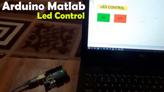
Controlling led using Arduino and MATLAB GUI:
Matlab Arduino to Control an Led using Serial communication- As a beginner, the very first project that almost everyone starts with is to control an LED using Arduino, because it’s simple to understand how to turn ON and turn OFF any IO pin. In this tutorial, we will do the same thing that is we will control an LED but this time we will use the GUI application designed in MATLAB. GUI stands for Graphical User Interface. Unlike other programming languages like “VB.net, Visual C++, C#, Python, etc” in Matlab we can also design GUIs. Another best thing is you don’t need the Arduino code, the Matlab GUI will do everything. You gonna love this, you don’t even need to write a single line of code in Arduino. All you need is to connect the LED with the Arduino and then connect the Arduino with the Computer or Laptop and you are good to go.
But, initially, you will need to install the Matlab support package for Arduino hardware, because without it you won’t be able to control the Arduino board. You can also read my article on how to install the Matlab software and how to start using it.
The reason I am starting with the LED is that an LED can be easily arranged. If you don’t have the LED then you can use the Arduino’s onboard LED connected with the digital pin 13. Anyways, in this tutorial, we will connect the LED with pin 3 of the Arduino. If you are able to control an LED then you can control a Transistor, Mosfet, or a relay, etc, and this way you can control higher loads. For easy understanding I will add only two button, one button will be used to turn ON the LED and the other button will be used to turn OFF the LED. Without any further delay let’s get started!!!
Amazon Links:
Arduino Nano USB-C Type (Recommended)
*Disclosure: These are affiliate links. As an Amazon Associate I earn from qualifying purchases.
LED interfacing with Arduino:
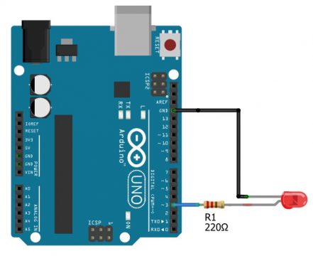
The Anode side of the LED is connected with pin 3 of the Arduino through a 220-ohm current limiting resistor. You can also use a 330-ohm resistor. Read more about the current limiting resistor. The cathode side of the LED is connected with the ground. That’s all about the connection. Serioulsy this is the simplest cirucit that we can start with.
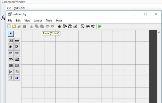
Matlab GUI Designing for Arduino:
Once your hardware is setup. Then Open the Matlab Software and to make the GUI application simply type guide in the command window and press enter this will open the untitled.fig. This is your form where you can add buttons, labels, check boxes etc.
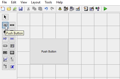
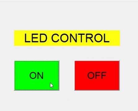
GUI window will appear, now we will create two buttons which will be used to turn ON and turn OFF the LED. So we will click the push button and drag to the size.
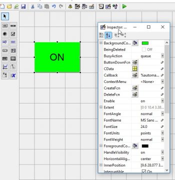
Now click on the button and a new window will open, which will show the properties of the button, in which we can change the color of the button and give a title to the button. As this button will be used to turn ON the LED, we will give it title ON and select the color green for this button and in the Tag section we will write on.
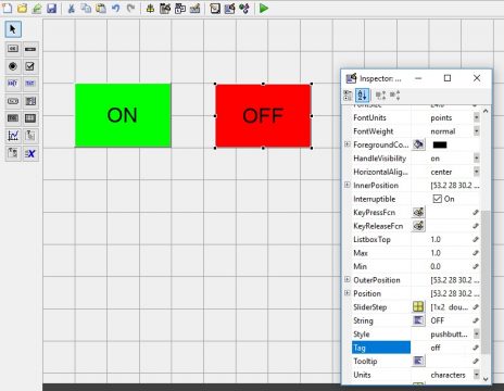
Similarly, we will insert another push button which we gonna be using for turning OFF the LED. We can insert another push button or just copy the ON button and paste it. Now we will change the color of the button to red and change the title to OFF and also change the Tag to off.
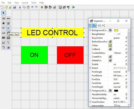
Now, to add a label simply click on the label “static text” and click on the GUI, then go ahead resize the label, write the text you want to display. In my case I will start with the “LED CONTROL” text. You can add multiple labels as per your requirement.
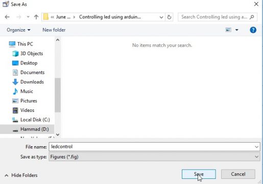
Now we will save the project, go to the file menu > click on the save and select the location where you want to save the file.
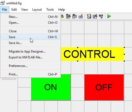
Now give the name ledcontrol to the project and click on the save button.
After saving the file the code will open

Now we have to declare all the functions that we are going to use so before that we need to declare some variables that we are going to use.
|
1 2 3 4 5 6 7 8 9 10 11 12 13 |
function varargout = ledcontrol_OutputFcn(hObject, eventdata, handles) % varargout cell array for returning output args (see VARARGOUT); % hObject handle to figure % eventdata reserved - to be defined in a future version of MATLAB % handles structure with handles and user data (see GUIDATA) % Get default command line output from handles structure varargout{1} = handles.output; |
A function called clear all and global “a” so this is the variable I am going to use for my Arduino.
|
1 2 3 |
clear all; global a; a = arduino; |
Now we will declare the function, when you press the push button “ON” what tasks to do and type that global a and when you press the ON button the LED has to turn ON. for that we need to write a function called writeDigitalPin my digital pin in the “a” comma that is the this is available to be used for Arduino. So that is a reason I am using a comma the pin that I connected my LED is D3 comma and a value is 1.
|
1 2 3 4 5 6 7 8 9 |
function on_Callback(hObject, eventdata, handles) % hObject handle to on (see GCBO) % eventdata reserved - to be defined in a future version of MATLAB % handles structure with handles and user data (see GUIDATA) global a; writeDigitalPin(a,'D3',1); |
Now when we will click on the turn off button the led will turn off now for the off button we will write the function
|
1 2 3 4 5 6 7 8 9 |
function off_Callback(hObject, eventdata, handles) % hObject handle to off (see GCBO) % eventdata reserved - to be defined in a future version of MATLAB % handles structure with handles and user data (see GUIDATA) global a; writeDigitalPin(a,'D3',0); |
Now the code is completed and we will check our program first we will save the code and then click on the run button. When we will click on the run button the led will turn ON and when we click on the turn off the led will turn OFF.
Copy the following code, or you can download the ledcontrol.fig and ledcontrol.m files.
Arduino Matlab GUI Complete code:
|
1 2 3 4 5 6 7 8 9 10 11 12 13 14 15 16 17 18 19 20 21 22 23 24 25 26 27 28 29 30 31 32 33 34 35 36 37 38 39 40 41 42 43 44 45 46 47 48 49 50 51 52 53 54 55 56 57 58 59 60 61 62 63 64 65 66 67 68 69 70 71 72 73 74 75 76 77 78 79 80 81 82 83 84 85 86 87 88 89 90 91 92 93 94 95 96 97 98 99 100 101 102 103 104 105 106 107 108 109 110 111 112 113 114 115 116 117 118 119 120 121 122 123 124 125 126 127 128 129 130 131 132 133 134 135 136 137 138 139 140 |
function varargout = ledcontrol(varargin) % LEDCONTROL MATLAB code for ledcontrol.fig % LEDCONTROL, by itself, creates a new LEDCONTROL or raises the existing % singleton*. % % H = LEDCONTROL returns the handle to a new LEDCONTROL or the handle to % the existing singleton*. % % LEDCONTROL('CALLBACK',hObject,eventData,handles,...) calls the local % function named CALLBACK in LEDCONTROL.M with the given input arguments. % % LEDCONTROL('Property','Value',...) creates a new LEDCONTROL or raises the % existing singleton*. Starting from the left, property value pairs are % applied to the GUI before ledcontrol_OpeningFcn gets called. An % unrecognized property name or invalid value makes property application % stop. All inputs are passed to ledcontrol_OpeningFcn via varargin. % % *See GUI Options on GUIDE's Tools menu. Choose "GUI allows only one % instance to run (singleton)". % % See also: GUIDE, GUIDATA, GUIHANDLES % Edit the above text to modify the response to help ledcontrol % Last Modified by GUIDE v2.5 15-Jun-2021 13:48:36 % Begin initialization code - DO NOT EDIT gui_Singleton = 1; gui_State = struct('gui_Name', mfilename, ... 'gui_Singleton', gui_Singleton, ... 'gui_OpeningFcn', @ledcontrol_OpeningFcn, ... 'gui_OutputFcn', @ledcontrol_OutputFcn, ... 'gui_LayoutFcn', [] , ... 'gui_Callback', []); if nargin && ischar(varargin{1}) gui_State.gui_Callback = str2func(varargin{1}); end if nargout [varargout{1:nargout}] = gui_mainfcn(gui_State, varargin{:}); else gui_mainfcn(gui_State, varargin{:}); end % End initialization code - DO NOT EDIT % --- Executes just before ledcontrol is made visible. function ledcontrol_OpeningFcn(hObject, eventdata, handles, varargin) % This function has no output args, see OutputFcn. % hObject handle to figure % eventdata reserved - to be defined in a future version of MATLAB % handles structure with handles and user data (see GUIDATA) % varargin command line arguments to ledcontrol (see VARARGIN) % Choose default command line output for ledcontrol handles.output = hObject; % Update handles structure guidata(hObject, handles); % UIWAIT makes ledcontrol wait for user response (see UIRESUME) % uiwait(handles.figure1); % --- Outputs from this function are returned to the command line. function varargout = ledcontrol_OutputFcn(hObject, eventdata, handles) % varargout cell array for returning output args (see VARARGOUT); % hObject handle to figure % eventdata reserved - to be defined in a future version of MATLAB % handles structure with handles and user data (see GUIDATA) % Get default command line output from handles structure varargout{1} = handles.output; clear all; global a; a = arduino; % --- Executes on button press in on. function on_Callback(hObject, eventdata, handles) % hObject handle to on (see GCBO) % eventdata reserved - to be defined in a future version of MATLAB % handles structure with handles and user data (see GUIDATA) global a; writeDigitalPin(a,'D13',1); % --- Executes on button press in off. function off_Callback(hObject, eventdata, handles) % hObject handle to off (see GCBO) % eventdata reserved - to be defined in a future version of MATLAB % handles structure with handles and user data (see GUIDATA) global a; writeDigitalPin(a,'D13',0); |
Final Testing:
Now all you need is to connect the Arduino with the Laptop or Computer and run the GUI by clicking on the play button. The Matlab will automatically detect the comport and as I said earlier you don’t need the Arduino code. Anyway, when you have run your Matlab GUI, you should be able to control the LED using the two push buttons ON and OFF. Watch the demonstration video given below. In the video I am controlling the onboard led connected with pin13 of the Arduino.
Watch Video Tutorial:
Discover more from Electronic Clinic
Subscribe to get the latest posts sent to your email.


