Multiplexer in Digital Electronics, Block Diagram, Designing, and Logic Diagram
Table of Contents
Multiplexer Description:
Multiplexer- Multiplexing is the process of combining the different communication channels and transfer it over a single transmission medium is called multiplexing. Three types of multiplexing techniques are used
- FDM (Frequency Division Multiplexing)
- TDM (Time Division Multiplexing)
- STDM (Statistical Time Division Multiplexing)
A multiplexer is a combinational logic circuit that receives 2n input lines and convert it into a single output line. The selection of the particular line depends upon the selection line. Who’s bit combination determines the selected line.
If we have 2n input lines then n is the selection lines.
Multiplexer Block Diagram:
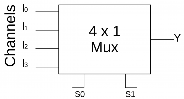
Block diagram of the 4×1 Multiplexer is given below
Designing Steps:
- Problem Design: 4×1 Mux
- The number of available inputs 4
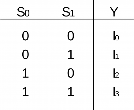
- Let the input channels are represented by I0, I1, I2, and I3; and the output is represented by the Y. The selection lines are represented by S0 and S1.
- Truth Table
-
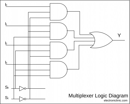
Multiplexer Logical Diagram
As you can see clearly a multiplexer logic diagram simply consists of 2 Not Gates, 4 AND Gates, and 1 OR Gate. The outputs of all the AND gates are added using a single OR Gate.
Amazon Purchase Links:
Adafruit TCA9548A I2C Multiplexer[ADA2717]
16 channel Analog Digital Multiplexer
*Please Note: These are affiliate links. I may make a commission if you buy the components through these links. I would appreciate your support in this way!
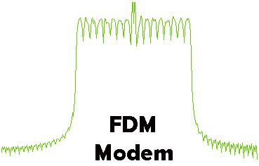
FDM (Frequency Division Multiplexing)
In telecommunications, frequency-division multiplexing (FDM) is a technique by which the total bandwidth available in a communication medium is divided into a series of non-overlapping frequency bands, each of which is used to carry a separate signal. This allows a single transmission medium such as a cable or optical fiber to be shared by multiple independent signals. Another use is to carry separate serial bits or segments of a higher rate signal in parallel.
The most natural example of frequency-division multiplexing is radio and television broadcasting, in which multiple radio signals at different frequencies pass through the air at the same time. Another example is cable television, in which many television channels are carried simultaneously on a single cable. FDM is also used by telephone systems to transmit multiple telephone calls through high capacity trunklines, communications satellites to transmit multiple channels of data on uplink and downlink radio beams, and broadband DSL modems to transmit large amounts of computer data through twisted pair telephone lines, among many other uses.
An analogous technique called wavelength division multiplexing is used in fiber-optic communication, in which multiple channels of data are transmitted over a single optical fiber using different wavelengths (frequencies) of light.
Frequency Division Multiplexing Working
The multiple separate information (modulation) signals that are sent over an FDM system, such as the video signals of the television channels that are sent over a cable TV system, are called baseband signals. At the source end, for each frequency channel, an electronic oscillator generates a carrier signal, a steady oscillating waveform at a single frequency that serves to “carry” information. The carrier is much higher in frequency than the baseband signal. The carrier signal and the baseband signal are combined in a modulator circuit. The modulator alters some aspect of the carrier signal, such as its amplitude, frequency, or phase, with the baseband signal, “piggybacking” the data onto the carrier.
The result of modulating (mixing) the carrier with the baseband signal is to generate sub-frequencies near the carrier frequency, at the sum (fC + fB) and difference (fC − fB) of the frequencies. The information from the modulated signal is carried in sidebands on each side of the carrier frequency. Therefore, all the information carried by the channel is in a narrow band of frequencies clustered around the carrier frequency, this is called the passband of the channel.
Similarly, additional baseband signals are used to modulate carriers at other frequencies, creating other channels of information. The carriers are spaced far enough apart in frequency that the band of frequencies occupied by each channel, the passbands of the separate channels, do not overlap. All the channels are sent through the transmission medium, such as a coaxial cable, optical fiber, or through the air using a radio transmitter. As long as the channel frequencies are spaced far enough apart that none of the passbands overlap, the separate channels will not interfere with each other. Thus the available bandwidth is divided into “slots” or channels, each of which can carry a separate modulated signal.
For example, the coaxial cable used by cable television systems has a bandwidth of about 1000 MHz, but the passband of each television channel is only 6 MHz wide, so there is room for many channels on the cable (in modern digital cable systems each channel in turn is subdivided into subchannels and can carry up to 10 digital television channels).
At the destination end of the cable or fiber, or the radio receiver, for each channel a local oscillator produces a signal at the carrier frequency of that channel, that is mixed with the incoming modulated signal. The frequencies subtract, producing the baseband signal for that channel again. This is called demodulation. The resulting baseband signal is filtered out of the other frequencies and output to the user.
TDM (Time Division Multiplexing)
Time-division multiplexing (TDM) is a method of transmitting and receiving independent signals over a common signal path by means of synchronized switches at each end of the transmission line so that each signal appears on the line only a fraction of time in an alternating pattern. It is a communication process that transmit 2 or more digital signals or analogue signals over a common channel. It is used when the bit rate of the transmission medium exceeds that of the signal to be transmitted. This form of signal multiplexing was developed in telecommunications for telegraphy systems in the late 19th century, but found its most common application in digital telephony in the second half of the 20th century.
Time Division Multiplexing History
Time-division multiplexing was first developed for applications in telegraphy to route multiple transmissions simultaneously over a single transmission line. In the 1870s, Émile Baudot developed a time-multiplexing system of multiple Hughes telegraph machines.
In 1944, the British Army used the Wireless Set No. 10 to multiplex 10 telephone conversations over a microwave relay as far as 50 miles. This allowed commanders in the field to keep in contact with the staff in England across the English Channel.
In 1953 a 24-channel TDM was placed in commercial operation by RCA Communications to send audio information between RCA’s facility on Broad Street, New York, their transmitting station at Rocky Point and the receiving station at Riverhead, Long Island, New York. The communication was by a microwave system throughout Long Island. The experimental TDM system was developed by RCA Laboratories between 1950 and 1953.
Time Division Multiplexing Technology
Time-division multiplexing is used primarily for digital signals, but may be applied in analog multiplexing in which two or more signals or bit streams are transferred appearing simultaneously as sub-channels in one communication channel, but are physically taking turns on the channel. The time domain is divided into several recurrent time slots of fixed length, one for each sub-channel. A sample byte or data block of sub-channel 1 is transmitted during time slot 1, sub-channel 2 during time slot 2, etc. One TDM frame consists of one time slot per sub-channel plus a synchronization channel and sometimes error correction channel before the synchronization. After the last sub-channel, error correction, and synchronization, the cycle starts all over again with a new frame, starting with the second sample, byte or data block from sub-channel 1, etc.
Time Division Multiplexing Application Examples
The plesiochronous digital hierarchy (PDH) system, also known as the PCM system, for digital transmission of several telephone calls over the same four-wire copper cable (T-carrier or E-carrier) or fiber cable in the circuit switched digital telephone network
The synchronous digital hierarchy (SDH)/synchronous optical networking (SONET) network transmission standards that have replaced PDH.
The Basic Rate Interface and Primary Rate Interface for the Integrated Services Digital Network (ISDN).
The RIFF (WAV) audio standard interleaves left and right stereo signals on a per-sample basis
TDM can be further extended into the time-division multiple access (TDMA) scheme, where several stations connected to the same physical medium, for example sharing the same frequency channel, can communicate. Application examples include:
The GSM telephone system
The Tactical Data Links Link 16 and Link 22
STDM (Statistical Time Division Multiplexing)
Statistical multiplexing is a type of communication link sharing, very similar to dynamic bandwidth allocation (DBA). In statistical multiplexing, a communication channel is divided into an arbitrary number of variable bitrate digital channels or data streams. The link sharing is adapted to the instantaneous traffic demands of the data streams that are transferred over each channel. This is an alternative to creating a fixed sharing of a link, such as in general time division multiplexing (TDM) and frequency division multiplexing (FDM). When performed correctly, statistical multiplexing can provide a link utilization improvement, called the statistical multiplexing gain.
Statistical multiplexing is facilitated through packet mode or packet-oriented communication, which among others is utilized in packet switched computer networks. Each stream is divided into packets that normally are delivered asynchronously in a first-come first-served fashion. In alternative fashion, the packets may be delivered according to some scheduling discipline for fair queuing or differentiated and/or guaranteed quality of service.
Statistical multiplexing of an analog channel, for example a wireless channel, is also facilitated through the following schemes:
Random frequency-hopping orthogonal frequency division multiple access (RFH-OFDMA)
Code-division multiple access (CDMA), where different amount of spreading codes or spreading factors can be assigned to different users.
Statistical multiplexing normally implies “on-demand” service rather than one that preallocates resources for each data stream. Statistical multiplexing schemes do not control user data transmissions.
Statistical multiplexing
In digital audio and video broadcasting, for example, a statistical multiplexer is a content aggregating device that allows broadcasters to provide the greatest number of audio or video services for a given bandwidth by sharing a pool of fixed bandwidth among multiple services or streams of varying bitrates. The multiplexer allocates to each service the bandwidth required for its real-time needs so that services with complex scenes receive more bandwidth than services with less complex ones. This bandwidth sharing technique produces the best video quality at the lowest possible aggregate bandwidth.
Examples of statistical multiplexers include the Imagine Communications (RGB Networks) BNPXr product line, Harmonic Inc. ProStream, Electra and VOS product families or the Motorola (Terayon) DM6400 and TMIR.
Usage of Statistical Time Division Multiplexing
Examples of statistical multiplexing are:
The MPEG transport stream for digital TV transmission. Statistical multiplexing is used to allow several video, audio and data streams of different data rates to be transmitted over a bandwidth-limited channel (see Statistical multiplexer). The packets have constant lengths. The channel number is denoted Program ID (PID).
The UDP and TCP protocols, where data streams from several application processes are multiplexed together. The packets may have varying lengths. The port numbers constitute channel identification numbers (and also address information).
The X.25 and Frame relay packet-switching protocols, where the packets have varying lengths, and the channel number is denoted virtual connection identifier (VCI). The international collection of X.25 providers, using the X.25 protocol suite was colloquially known as “the Packet switched network” in the 1980s and into the beginning of the 1990s.
The Asynchronous Transfer Mode packet-switched protocol, where the packets have fixed length. The channel identification number consists of a virtual connection identifier (VCI) and a Virtual Path Identifier (VPI).
Demultiplexer.


