Demultiplexer in Digital Electronics: Block Diagram, Truth Table, & Logic Diagram
Table of Contents
Description:
A Demultiplexer or Demux in digital electronics is a circuit that takes a single input line and routes it to one of several digital output lines. A Demultiplexer of 2n outputs has n select lines, which are used to select which output line to send the input. A Demultiplexer is also called a data distributor.
Demultiplexers in digital electronics can be used to implement general-purpose logic. By setting the input to true, the Demux behaves as a decoder.
A Decoder with an enable input can function as a Demultiplexer. A Demultiplexer is a circuit that receives information on a single line and transmits this information on one of 2n possible output lines. The selection of a specific output line is controlled by the bit values combination of n selection lines determined.
The reverse of the digital Demultiplexer is the digital multiplexer.
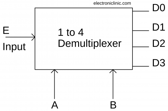
1 to 4 Demultiplexer Block Diagram:
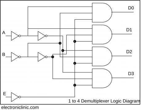
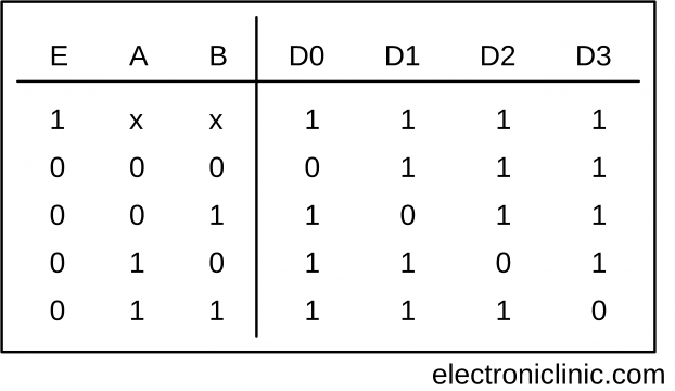
A 1 to 4 Demultiplexer uses 2 select lines (A, B) to determine which one of the 4 outputs (D0 – D3) is routed from the input (E). Its characteristics can be described in the following simplified truth table.
1 to 4 Demultiplexer Truth Table:
1 to 4 Demultiplexer Logic Diagram:
List of ICs which provide Demultiplexing
| IC No. (7400) | IC No. (4000) | Function | Output State |
| 74139 | Dual 1:4 demux. | Output is inverted input | |
| 74156 | Dual 1:4 demux. | Output is open collector | |
| 74138 | 1:8 demux. | Output is inverted input | |
| 74238 | 1:8 demux. | ||
| 74154 | 1:16 demux. | Output is inverted input | |
| 74159 | CD4514/15 | 1:16 demux. | Output is open collector and same as input |
Some of the most commonly used electronic components and tools available on Amazon.
*Please Note: These are affiliate links. I may make a commission if you buy the components through these links. I would appreciate your support in this way!
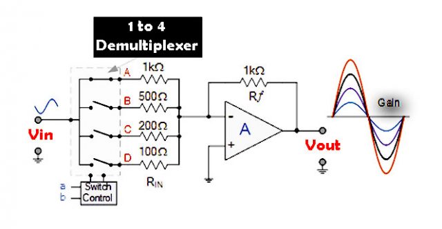
Digitally Adjustable Amplifier Gain
The circuit above illustrates how to provide digitally-controlled adjustable/variable op-amp gain using a Demultiplexer. The voltage gain of the inverting operational amplifier is dependent upon the ratio between the input resistor, RIN and its feedback resistor, Rƒ as determined in the Op-amp tutorials.
The digitally controlled analogue switches of the Demultiplexer select an input resistor to vary the value of Rin. The combination of these resistors will determine the overall voltage gain of the amplifier, (Av). Then the voltage gain of the inverting operational amplifier can be adjusted digitally simply by selecting the appropriate input resistor combination.
Standard Demultiplexer IC packages available are the TTL 74LS138 1 to 8-output Demultiplexer, the TTL 74LS139 Dual 1-to-4 output Demultiplexer or the CMOS CD4514 1-to-16 output Demultiplexer.
Another type of Demultiplexer is the 24-pin, 74LS154 which is a 4-bit to 16-line Demultiplexer/decoder. Here the individual output positions are selected using a 4-bit binary coded input. Like multiplexers, Demultiplexers can also be cascaded together to form higher order Demultiplexers.
Unlike multiplexers which convert data from a single data line to multiple lines and Demultiplexers which convert multiple lines to a single data line, there are devices available which convert data to and from multiple lines and in the next tutorial about combinational logic devices, we will look at Encoders which convert multiple input lines into multiple output lines, converting the data from one form to another.
Use of Multiplexer and Demultiplexer:
These applications include the following: Communication System – Multiplexer and Demultiplexer both are used in communication systems to carry out the process of data transmission. A De-multiplexer receives the output signals from the multiplexer; and, at the receiver end, it converts them back to the original form.
Other Digital Electronics Related Topics:
Subtractor in Digital Electronics
SOP and Digital Logic Designing
Karnaugh Map in Digital Electronics
Logic Gates in Digital Electronics
