Subtractor in Digital Electronics, Half Subtractor and Full Subtractor
Subtractor:
A combinational circuit that performs the subtractions of bits is called a Subtractor. There are two types of Subtractors.
- Half Subtractor
- Full Subtractor
-
Half Subtractor:
A combinational circuit that performs the subtraction of two bits is called Half Subtractor. It receives two inputs and produces two outputs Difference and Borrow. The block diagram of the Half Subtractor is given as
Half Subtractor Block diagram:
Designing of a Half Subtractor:
The designing of the half Subtractor involves the following steps.
- Problem: Subtraction of two bits
- The number of available inputs 2.
- The input and output variables are assigned letter symbols. Let we represent the inputs by A and B, and the outputs Difference and Borrow by D and B.
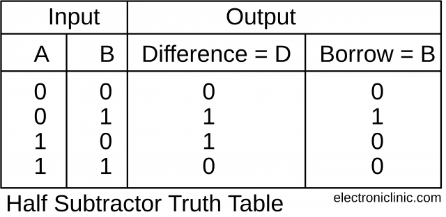
- Half Subtractor Truth Table:
- Simplified Boolean function:
It cannot be further simplified so,
-
Half Subtractor Logical Diagram:
The logical diagram for the difference can be obtained by using the exclusive OR-Gate.
Amazon Purchase Links:
CD4000 Series KIT IC Cabinet Kit, Series 4000 CMOS
Digital Logic Gates 200 Exploration Kit
74LS Series KIT 420 Piece 74LS Logic Series Component Kit
Other Tools and Components:
Super Starter kit for Beginners
PCB small portable drill machines
*Please Note: These are affiliate links. I may make a commission if you buy the components through these links. I would appreciate your support in this way!
Full Subtractor:
A combinational circuit that performs the subtraction of three bits is called a Full Subtractor. It receives three inputs and produces two outputs Difference and Borrow. The Block Diagram of the Full Subtractor is as follows.
Full Subtractor Block Diagram:
The designing of the Full Subtractor involves the following steps.
- Problem: Subtraction of three bits
- The number of available inputs are 3.
- The input and output variables are assigned letter symbols. Let we represent the inputs by A, B, and C; and the outputs Difference and Borrow by D and B.
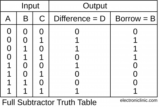
- Full Subtractor Truth Table:
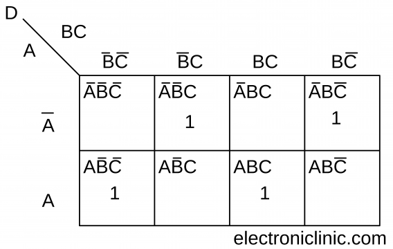
- Simplified Boolean Function of the Full Subtractor:
Simplifying the above Boolean function by using the Karnaugh Map K.Map
The full Subtractor function cannot be further simplified.
-
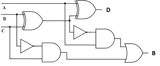
Full Subtractor Logical Diagram:
The half subtractors designed can be used in the construction of full subtractors. When the two half subtractors are cascaded together such that the Difference output generated at the first stage is connected to the second subtractor as the input.
Initially, the inputs A and B are applied to the left-most circuit. Based on the functionality it generates Difference and Borrows as output. At the right circuit that is the second stage of Half subtractor Difference and the Borrow in, a bit is applied as the input. After processing, the output bit named as Difference is generated. But the borrow bit is produced in both the stages is applied to the OR gate to obtain the final Borrow out.

