Codes in digital electronics, BCD, Excess-3, Error Detection, ASCII, Gray Code
Table of Contents
Description:
Codes in Digital Electronics– In this article we will talk about different Codes “BCD Code, Excess-3 Code, Error Detecting Code, ASCII code, and Gray Code/ Reflected Code” used in digital electronics.
Code:
Code is used to represent some type of information. In computers and digital circuits, the different codes are used to represent the information or data.
BCD Code in Digital Electronics:
BCD stands for Binary Coded Decimal. This code is used to represent a decimal number into a binary number. In BCD each number is expressed in 4-bits i.e. a string of nibble. Let me give you an example. Let’s say, for example, we want to convert a decimal number 2945 to BCD number.
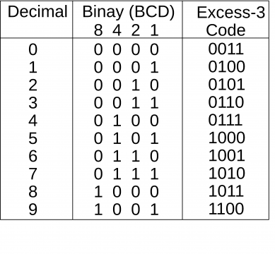
We will simply start with a truth table, consisting of the decimal numbers and their equivalent Binary (BCD) codes.
BCD Codes Table:
Now we can write the binary (BCD) equivalent codes of each number.
2 = 0010
9 = 1001
4 = 0100
5 = 0101
So,
(2945)Decimal = (0010100101000101)BCD
BCD numbers are useful for the places where decimal information are transferred into or out of a digital system. For example the circuit inside the pocket calculators can process BCD numbers, because you enter a decimal number through a keypad, and see the decimal result on the display. Other examples of the BCD systems are electronic counters, digital clocks, Medical equipments, Electronic voltmeters, etc.
The following table shows the BCD numbers.
From 10 to 15 it is considered as the don’t care, because if we want to enter (10) with the keyboard or keypad, first we press 1 who’s binary value is sent and then we press 0, a binary value of zero is sent. So that’s why in BCD we consider numbers and their codes from 0 to 9.
Excess-3 Code in Digital Electronics:
A decimal code that has been used in some old computers is the Excess-3 code. This is an unweighted code; its code assignment is obtained from the corresponding value of BCD after the addition of 3.
The following table shows the representation/conversion of the BCD code into Excess-3 code.
For 0: Add 0000 with 0011(3)
For 1: Add 0001 with 0011
Similarly for the remaining.
BCD code conversion into 8 4 -2 -1 code:
Let’s start with a truth table.
From 1 to 4 we consider 2 on the right side and for numbers greater than 4 we consider 2 on the left side. Let me give you an example. Let’s say we want to convert 2 into 2 4 2 1 code. As 2 is less than 4 so will consider 2 which is on the right side. So the binary value will be
From the truth table you can see
2 = 1000 and
2 = 0010
As I said earlier, if the number is less than 4 then we will consider the 2 which is on the right side. So, the correct value is 0010.
Let’s convert 8 into 2 4 2 1 code.
From the truth table, as 8 is greater than 4, so this time we will consider 2 which is on the left side. So the binary value will be 1110. Similarly for the other numbers.
Error Detecting Code in Digital Electronics:
Convert (23)10 in 8 4 -2 -1
2 = 0110
3 = 0101
(23)10 = (01100101)2
Are you confused, how this is done?
Let’s start with a very simple example,
Convert 2 into 8 4 -2 -1.
If you look in the truth table, we find that if we add 4 and -2 we get 2.
4 + (-2)
4 – 2 = 2
So we ON the 4 and -2 and we get
2 = 0110
Similarly let’s convert 7 into 8 4 -2 -1 code
In the truth table you can see if we add 8 and -1 we get 7. So the binary equivalent value will be
7 = 1001
And similarly for the other decimal numbers, this way how easily decimal numbers can be converted into BCD code, and 8 4 -2 -1 code.
Error Detecting Code in Digital Electronics:
Data/information is transmitted in the form of binary numbers (1 or 0) through some form of communication medium, such as wires or Radio waves. During this transmission errors can occur in the binary information i.e. ( 0 to 1 or 1 to zero) 0 may become 1 or 1 may become 0. An error detecting code can be used to detect errors during transmission. The detected error cannot be corrected, but its presence is indicated.
This is done with the help of Parity bit. A parity bit is an extra bit included with a message for the purpose of detecting errors and making the total number of 1’s either odd or even. We have two types of parity bits Odd Parity and Even Parity.
Odd Parity:
The total number of 1’s in an odd must be odd.
Even Parity:
The total number of 1’s in an even parity must be even.
From one location to another location, the parity bit is handled as follows.
On the sending side, the message ( in this case the first four bits) is applied to a parity generator, where the required parity bit is generated. The message including the parity bit is transferred to its destination.
On the receiving end, all the incoming bits are applied to a “Parity Checker”, the parity bit is inhaled by the parity checker and the message is transferred to the destination.
The following Truth Table shows the Parity Bit generation.
Gray Code / Reflected Code:
Gray Code / Reflected Code is also called as the 1 bit shift. In Gray code first of all, the decimal number is converted into the BCD, then after performing some process Gray Code / Reflected Code is obtained.
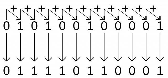
Digital systems can be designed to process data in discrete form only. Many physical systems supply continuous output data. This data must be converted into digital or discrete form before they are applied to a digital system. Continuous or Analog information is converted into digital form by means of an analog to digital converter. It is some time convenient to use the reflected code to represent the digital data converted from the analog data. The advantage of the reflected code over pure binary numbers is that a number in reflected code changes by only one bit as it proceeds from one number to the next.In reflected code first of all, the given decimal number is converted into the BCD. Suppose we have to convert a decimal number 521 into Gray Code, the process will be,
- First of all, we convert the 521 into BCD.
As per the very first truth table given above.
5 = 0101
2 = 0010
1 = 0001
So,
(521)10 = 010100100001
- Then we write the first digit as it is and then adding the every next digit with the previous one. If the carry is generated it’s discarded.
So the Gray Code / Reflected Code of the number 521 is 011110110001.
ASCII Code:
ASCII stands for the American standard code for information interchange. ASCII has been adopted by several American computer manufacturers as their computer’s internal code. ASCII is of two types ASCII-7 and ASCII-8.
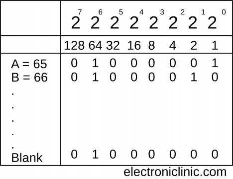
ASCII-7 is a 7-bit code that allows 128 (2)7 different characters. The first three bits are used as zone bits and the last 4-bits indicate the digit.
ASCII-8 is an extended version of ASCII-7. It is an 8-bit code that is, it uses eight bits to represent a letter or a punctuation mark. Eight bits are called a byte. A binary code with eight digits, such as 1001 10112, can be stored in one byte of computer memory.
Possible combinations 28 = 256
From 0 to 255.
I hope you have learned something from this article.


