NRF24L01 Multiple Transmitters and Single Receiver for Sensor Monitoring using Arduino
Last Updated on August 17, 2024 by Engr. Shahzada Fahad
Table of Contents
NRF24L01 Multiple Transmitters, Description:
NRF24L01 Multiple Transmitters and Single Receiver– Using the NRF24L01 transceiver modules you can monitor and control different processes.
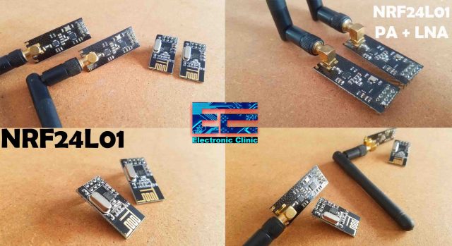
You can either use a pair of the long-range NRF24L01 PA + LNA transceiver modules, or you can use a pair of the short-range NRF24L01 Transceiver modules. You can also make a pair by using the NRF24L01 PA+LNA with the regular small size NRF24L01 transceiver module. The communication between the two NRF24L01 Transceiver modules is very simple as explained in my previous 4 tutorials.
In Tutorial1 I explained how to make a long range 12V battery voltage monitoring system using a pair of NRF24L01 Transceiver modules with the HC05 Bluetooth module. I was able to monitor the voltage of a 12V battery using my android cell phone application.
In tutorial2, I designed a long range industrial temperature monitoring system and this time instead of using the android cell phone application, I displayed the temperature values on the Oled Display module. In this project as well I just used a pair of NRF24L01 Transceiver modules and only one Temperature Sensor. So, all I want to say is that it’s very simple to use a pair of NRF24L01 Transceiver modules and a single sensor. But there might be situations when you need to monitor multiple sensors.
So in my third tutorial, I explained how to connect multiple sensors with the Transmitter side Arduino and displayed the values on the Serial monitor on the Receiver side Arduino. In this tutorial, I have explained how to use an array to store all the sensor values and then how to access each sensor value on the receiver side. In this tutorial as well I just used a pair of NRF24L01 Transceiver modules, but this time I used multiple sensors on the transmitter side instead of using one sensor. In this tutorial, I also explained how to send a string message.
In my 4th tutorial, I used a pair of the long range NRF24LO1 PA+LNA transceiver modules for controlling the RC Jet Plane. I was able to control the up-down and left-right movement of the RC plane. I was also able to control the speed of the Brushless DC motor. In this tutorial, I used multiple sensors on the transmitter side to control the RC jet plane.
Things get a little complicated when it comes to multiple NRF24L01 transmitters and a single receiver. This is what I am going to explain in this article, but first a few words about the Sponsor.
About the Sponsor, PCBWay:

High quality & Only 24 Hours Build time
The PCB boards used in this project are sponsored by the PCBWay Company. Only 5 dollars for 10 PCBs and 30 dollars in total for 20 PCBs Assembly. Besides this PCBWay also provides a great variety of services including Aluminum PCB, Rigid-Flex, Metal Core, flexible, High Frequency, High-TG, Thick-Copper, HDI, and LED PCBs. The sign up process hardly takes 1 minute and you are welcomed with a 5 dollars welcome bonus, what are you waiting for go and get your first prototype order for free.
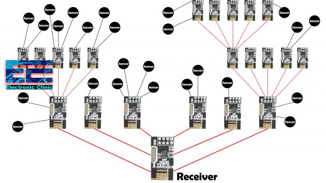
As I said earlier, things get a little complicated when it comes to multiple sensors connected with multiple transmitters. The sensors values from the multiple transmitters based on the NRF24L01 Transceiver modules are sent to the single receiver. Now, at the receiver side, you should know exactly which value belongs to which sensor and from which transmitter the sensor value is received. The red lines represent the wireless communication link.
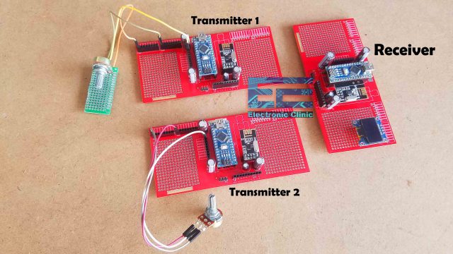
The transmitter1 and receiver circuits were used in the Long-range industrial temperature monitoring system. Now to explain the idea of how to use multiple NRF24L01 transmitters with a single receiver I made another Transmitter2 circuit. For demonstration purposes, I will use only two transmitters, but you can increase the number of transmitters which I will later explain in this article. So, as you can see both the transmitters are exactly the same. I have connected two potentiometers which I will use as the sensors. You can also increase the number of sensors as I have already used an array in the programming which can be used to store values of the multiple sensors.
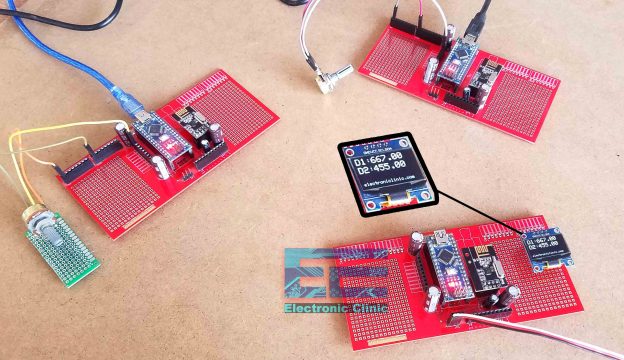
The two transmitters and the receiver circuit are powered up to check how these transmitters communicate with the receiver. D1 is the value coming from the Transmitter number1 and D2 is the values coming from the transmitter number2. The reason I am using potentiometers because they can be easily found in any electronics shop. Anyhow, I know exactly which value is coming from the Transmitter number1 and which value is coming from the transmitter number2. The question is how Arduino knows this? It’s very simple, along with the sensor value I also send the header value. The header values of both the transmitters are different. I am using a header value of 231 for the transmitter1 and 434 for the transmitter2, these header values remain constant through the communication. I will explain this in the programming section.
Next, I did the same exact thing using the RF24Network library which can be used to make a complete network.
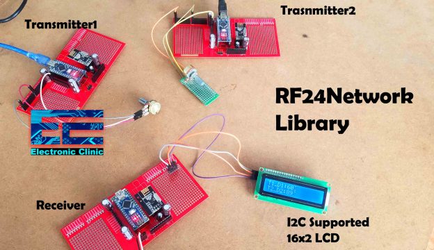
This time I displayed the values on the i2c supported 16×2 LCD. If you have more than six NRF24L01 Transceiver modules and you want to perform one way or two-way communication then I highly recommend using the RF24Network Library. Now, you know exactly what you are going to learn after reading this article. Without any further delay let’s get started!!!
Amazon Purchase Links:
Arduino Nano USB-C Type (Recommended)
*Disclosure: These are affiliate links. As an Amazon Associate I earn from qualifying purchases.
NRF24L01 Wireless Network Topology:
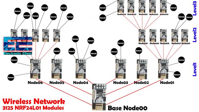
You might be thinking about the maximum number of NRF24L01 Transceiver modules that can be used in a wireless sensor network. A single NRF24L01 module can actively listen up to 6 other modules at the same time.
Where one node is the base, and all other nodes are children of either that node or of another. Each node can have up to 5 children, and this can go 5 levels deep, which means we can create a network of total 3125 nodes. Each node must be defined with a 15-bit address, which precisely describes the position of the node within the tree.
To keep things simpler I will only stick to the level 1. You can use 6 transmitters at the same time to which you can connect multiple sensors. Now let’s take a look at the circuit diagrams.
NRF24L01 Multiple Transmitters, Circuit Diagrams:
NRF24L01 Transmitter1, circuit Diagram:

This is the circuit diagram of the transmitter1 which is very simple. A potentiometer is connected with the Analog pin A0. A decoupling capacitor of 10uf is connected with the VCC and GND pins of the NRF24L01 module. The VCC and GND pins are connected with the Arduino’s 3.3V and GND pins. CE is connected with Pin9, CSN is connected with Pin10, SCK is connected with 13, MOSI is connected with Pin11, and the MISO pin is connected with Pin12 of the Arduino.
NRF24L01 Transmitter2, circuit Diagram:
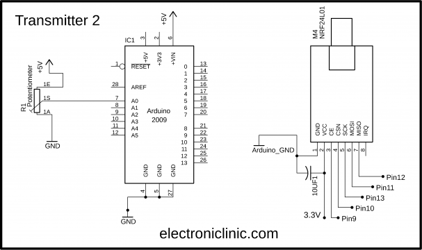
This is the circuit diagram of the transmitter2 which is exactly the same. The same way you can make 4 more transmitter circuits, and if you want you can also increase the number of sensors. Now, let’s take a look at the receiver circuit diagram.
NRF24L01 Receiver Circuit Diagram:
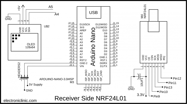
The NRF24L01 connection with the Arduino remains exactly the same. An I2C supported 128×64 Oled display module is connected with the Arduino. The SCL and SDA pins of the Oled display module are connected with the A5 and A4 pins while the VCC and GND pins of the display module are connected with the 5V and GND pins of the Arduino. I also added male headers for connecting the 5V regulated power supply.
The PCB designing and soldering I have already explained in my previous tutorial based on the long range wireless industrial temperature monitoring system. Now, let’s take a look at the programming.
NRF24L01 Multiple Transmitters and Single Receiver, Arduino Codes:
As usual before you start the programming first of all, make sure you download all the necessary libraries. Both the codes are exactly the same except these two values stored at the 0 location in the array. So, let’s take a look at the transmitter 1 programming.
NRF24L01 Transmitter1 Arduino Code:
|
1 2 3 4 5 6 7 8 9 10 11 12 13 14 15 16 17 18 19 20 21 22 23 24 25 26 27 28 29 30 31 32 33 34 35 36 |
//Transmitter1 coding for the nrf24L01 radio transceiver. //https://www.electroniclinic.com/ #include <SPI.h> #include <nRF24L01.h> #include <RF24.h> #define CE_PIN 9 #define CSN_PIN 10 const uint64_t pipe = 0xE8E8F0F0E1LL; RF24 radio(CE_PIN, CSN_PIN); float data[4]; // depending on the number of sensors you want to use int vresistor = A0; int vrdata; void setup() { Serial.begin(9600); radio.begin(); radio.openWritingPipe(pipe); pinMode(vresistor,INPUT); } void loop() { // read the value at analog input vrdata = analogRead(vresistor); data[0] = 231; // code to identify the transmitter. data[1] = vrdata; radio.write( data, sizeof(data) ); } |
Code explanation:
Maximum of the code I have already explained in my previous tutorials. I defined this array float data[4]; for storing the sensors values and the header. At location 0, I will store the header and at location 1, 2, and 3, I can store the sensors values, if you are using more sensors then you can simply increase the array size. Currently, I am using only one sensor which is connected with the Analog pin A0.
We simply read the Analog pin A0 and store the value in variable vrdata. Next, in the data array at location 0, I store the number 231 which will act as the code to identify the transmitter1 and then at location 1 in the data array we store the sensor value. If you have other sensor then store the value at location 2, and so on. Finally, we send the data array. Now let’s take a look the code of transmitter 2.
NRF24L01 Transmitter2 Arduino Code:
|
1 2 3 4 5 6 7 8 9 10 11 12 13 14 15 16 17 18 19 20 21 22 23 24 25 26 27 28 29 30 31 32 33 34 35 36 37 |
//Transmitter2 coding for the nrf24L01 radio transceiver. //https://www.electroniclinic.com/ #include <SPI.h> #include <nRF24L01.h> #include <RF24.h> #define CE_PIN 9 #define CSN_PIN 10 const uint64_t pipe = 0xE8E8F0F0E1LL; RF24 radio(CE_PIN, CSN_PIN); float data[4]; // depending on the number of sensors you want to use int vresistor = A0; int vrdata; void setup() { Serial.begin(9600); radio.begin(); radio.openWritingPipe(pipe); pinMode(vresistor,INPUT); } void loop() { // read the value at analog input vrdata = analogRead(vresistor); data[0] = 434; // code to identify the transmitter. data[1] = vrdata; radio.write( data, sizeof(data) ); } |
Code Explanation:
The transmitter2 code is exactly the same, except the value stored at location 1 which is 434. Now, if you have another transmitter all you need is to use a different number. Make sure to use different header values otherwise the receiver won’t be able to identify from which transmitter its receiving the data. Now, let’s take a look at the receiver side programming.
NRF24L01 Receiver Arduino Code:
|
1 2 3 4 5 6 7 8 9 10 11 12 13 14 15 16 17 18 19 20 21 22 23 24 25 26 27 28 29 30 31 32 33 34 35 36 37 38 39 40 41 42 43 44 45 46 47 48 49 50 51 52 53 54 55 56 57 58 59 60 61 62 63 64 65 66 67 68 69 70 71 72 73 74 75 76 77 78 79 80 81 82 83 84 85 86 87 88 89 90 91 92 93 94 95 96 97 98 99 100 101 102 103 104 105 106 107 108 109 110 111 112 113 114 115 116 117 118 119 120 121 122 123 124 125 126 127 128 129 130 131 132 133 134 135 136 137 138 139 140 141 142 143 144 145 |
//Receiver coding for the nrf24L01 radio transceiver. //https://www.electroniclinic.com/ // Download Libraries: //https://www.electroniclinic.com/arduino-libraries-download-and-projects-they-are-used-in-project-codes/ #include <Wire.h> #include <Adafruit_GFX.h> #include <Adafruit_SSD1306.h> #include <SPI.h> #include <nRF24L01.h> #include <RF24.h> #define CE_PIN 9 #define CSN_PIN 10 const uint64_t pipe = 0xE8E8F0F0E1LL; RF24 radio(CE_PIN, CSN_PIN); float data[4]; // depending on the number of sensors used unsigned long lastReceiveTime = 0; unsigned long currentTime = 0; float data1; float data2; #define SCREEN_WIDTH 128 // OLED display width, in pixels #define SCREEN_HEIGHT 64 // OLED display height, in pixels // Declaration for an SSD1306 display connected to I2C (SDA, SCL pins) #define OLED_RESET -1 // Reset pin # (or -1 if sharing Arduino reset pin) Adafruit_SSD1306 display(SCREEN_WIDTH, SCREEN_HEIGHT, &Wire, OLED_RESET); void setup() { Serial.begin(9600); delay(1000); Serial.println("Nrf24L01 Receiver Starting"); radio.begin(); radio.openReadingPipe(1,pipe); radio.startListening(); resetData(); display.begin(SSD1306_SWITCHCAPVCC, 0x3C); delay(2000); display.clearDisplay(); display.setTextColor(WHITE); } void loop() { if ( radio.available() ) { bool done = false; while (!done) { done = radio.read( data, sizeof(data) ); lastReceiveTime = millis(); // At this moment we have received the data if (data[0] == 231) // header { data1 = data[1]; Oled_display(); } if (data[0] == 434) // header { data2 = data[1]; Oled_display(); } delay(100); } } else { currentTime = millis(); if ( currentTime - lastReceiveTime > 1000 ) { // If current time is more then 1 second since we have recived the last data, that means we have lost connection resetData(); } } } void resetData() { display.clearDisplay(); display.setTextSize(2); display.setCursor(0,0); display.print("Connection"); display.setTextSize(3); display.setCursor(0, 28); display.print("Lost"); display.setTextSize(1); display.setCursor(0, 56); display.print("www.electroniclinic.com"); display.display(); } void Oled_display() { display.clearDisplay(); display.setTextSize(2); display.setCursor(0,0); display.print("D1:"); display.setTextSize(2); display.setCursor(35, 0); display.print(data1); display.setTextSize(2); display.setCursor(0,20); display.print("D2:"); display.setTextSize(2); display.setCursor(35, 20); display.print(data2); display.setTextSize(1); display.setCursor(0, 56); display.print("www.electroniclinic.com"); display.display(); } |
Code Explanation:
I added libraries for the Oled display module. I defined a data array of the same size and type. I also defined two variables data1 and data2 that are used to store the values coming from transmitter1 and transmitter2. All the other instructions I have already explained in my previous tutorial based on the long range wireless industrial temperature monitoring system. So, after the data is received then we use these two conditions to check whether the data received belongs to Transmitter1 or transmitter2. If the Arduino see 231 at location 0 the sensor value is stored in data1 and is then displayed on the Oled display module. If the Arduino see 434 at location 0 the sensor value is stored in data2 and is then displayed on the Oled display module.
Then finally some instruction used to check if the connection is lost and all of the other instructions are used to display the values on the Oled display module.
Using the RF24Network Library:
Now we will implement the same idea using the RF24Network Library. The libraries that you have already downloaded won’t work this time. Now, you will need to download the following libraries.
NRF24L01 based Transmitter and Receiver Circuits:
The transmitters will remain exactly the same, I made only one change to the receiver circuit and that is I replaced this I2C Oled display module with the I2C supported 16×2 LCD Module.
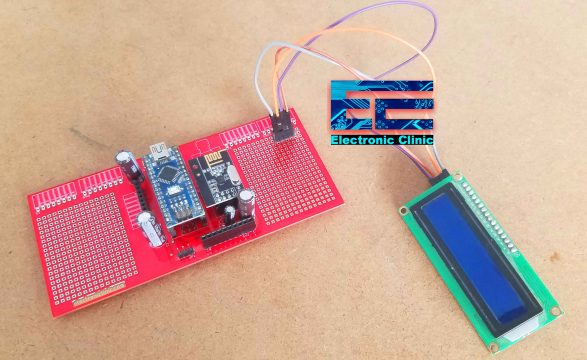
This time I am using the female headers for the 16×2 LCD. So this is the only modification that I did while everything else remains exactly the same. Now let’s take a look at the programming.
Multiple NRF24L01 Transmitters and Receiver Codes:
NRF24L01 Transmitter1 Arduino Code:
|
1 2 3 4 5 6 7 8 9 10 11 12 13 14 15 16 17 18 19 20 21 22 23 24 |
// Node01 #include <RF24.h> #include <RF24Network.h> #include <SPI.h> RF24 radio(9, 10); // nRF24L01 (CE,CSN) RF24Network network(radio); // Include the radio in the network const uint16_t this_node = 01; // Address of this node in Octal format const uint16_t node00 = 00; unsigned long data[6]; // number of sensors void setup() { SPI.begin(); radio.begin(); network.begin(90, this_node); //(channel, node address) radio.setDataRate(RF24_2MBPS); } void loop() { network.update(); unsigned long potValue = analogRead(A0); // Read the potentiometer value data[0] = potValue; RF24NetworkHeader header7(node00); bool ok = network.write(header7, &data, sizeof(data)); // Send the data } |
NRF24L01 Transmitter2 Arduino Code:
|
1 2 3 4 5 6 7 8 9 10 11 12 13 14 15 16 17 18 19 20 21 22 23 24 |
// Node02 #include <RF24.h> #include <RF24Network.h> #include <SPI.h> RF24 radio(9, 10); // nRF24L01 (CE,CSN) RF24Network network(radio); // Include the radio in the network const uint16_t this_node = 02; // Address of this node in Octal format const uint16_t node00 = 00; unsigned long data[6]; // number of sensors void setup() { SPI.begin(); radio.begin(); network.begin(90, this_node); //(channel, node address) radio.setDataRate(RF24_2MBPS); } void loop() { network.update(); unsigned long potValue = analogRead(A0); // Read the potentiometer value data[0] = potValue; RF24NetworkHeader header8(node00); bool ok = network.write(header8, &data, sizeof(data)); // Send the data } |
Code Explanation:
This time in addition to the RF24 library I also added the RF24Network library. One code is written for the transmitter number1 which is Node01 and the other code is written for the Transmitter number2 which is Node02. These two nodes communicate with the single receiver or base node00. You can see both the Codes are exactly the same except the nodes addresses. For the transmitter number1 the node address is 01 while for the transmitter number2 the node address is 02. You can copy and paste the same code to make another node03, and so on. Over here I am also using the data array, if in case you want to connect multiple sensors. In this code, there is no need to add a header, because this time the node addresses 01 and 02 will be used to identify the transmitters. Rest of the code is self explanatory; we simply read the sensor, store the sensor value in the array at location 0 and then send the data array to the receiver which is the base node00. Now, let’s take a look at the receiver programming.
NRF24L01 Receiver Arduino Code:
|
1 2 3 4 5 6 7 8 9 10 11 12 13 14 15 16 17 18 19 20 21 22 23 24 25 26 27 28 29 30 31 32 33 34 35 36 37 38 39 40 41 42 43 44 45 46 47 48 49 50 51 52 53 54 55 56 57 58 59 60 61 62 63 64 65 |
// Node00 #include <RF24.h> #include <RF24Network.h> #include <SPI.h> #include <Wire.h> #include <SimpleTimer.h> #include <LiquidCrystal_I2C.h> LiquidCrystal_I2C lcd(0x27,16,2); //0x27 is the i2c address, while 16 = columns, and 2 = rows. SimpleTimer timer; RF24 radio(9, 10); // nRF24L01 (CE,CSN) RF24Network network(radio); // Include the radio in the network const uint16_t this_node = 00; // Address of our node in Octal format unsigned long data[6]; // number of sensors unsigned long data1; unsigned long data2; void setup() { Serial.begin(9600); SPI.begin(); radio.begin(); network.begin(90, this_node); //(channel, node address) radio.setDataRate(RF24_2MBPS); lcd.init(); //Init the LCD lcd.backlight(); //Activate backlight lcd.home(); timer.setInterval(200L, lcdDisplay); } void loop() { timer.run(); network.update(); while ( network.available() ) { // Is there any incoming data? RF24NetworkHeader header; network.read(header, &data, sizeof(data)); // Read the incoming data if (header.from_node == 1) { // If data comes from Node 01 data1 = data[0]; } if (header.from_node == 2) { // If data comes from Node 02 data2 = data[0]; } } } void lcdDisplay() { lcd.clear(); lcd.setCursor(0,0); lcd.print("T1_D1:"); lcd.print(data1); lcd.setCursor(0,1); lcd.print("T2_D2:"); lcd.print(data2); } |
Code Explanation:
I added some libraries for the I2C supported 16×2 LCD. I also defined a timer that will control the 16×2 LCD. The address of this node is 00 which is the base node. I also defined data array of the same size and type. The data1 and data2 variables will store the sensor values. In the loop section, we start by constantly checking whether there is any incoming data. If so, we read the data, store it into the data array, next we use the two if conditions to check whether we are receiving the data from Node01 or Node02. In such a case, we use the header.from_node attribute in order to get information from which node does the data comes from. In case the incoming data is from the node01, we will store it in data1, and in case the incoming data is from the node02, we will store it in data2.
The lcdDisplay() function is executed after every 200 milliseconds to display the values on the 16×2 LCD.
Watch Video Tutorial:
Discover more from Electronic Clinic
Subscribe to get the latest posts sent to your email.


Disculpa que versiones de libreria utulizas?
Thank you so much for the nice project.
I am experiencing following compile error in the receiver code based on no NetworkLibray . Please help me to solve this error.
exit status 1
void value not ignored as it ought to be
Thank you so much for nice NRF24L01 project.
However, I am getting following complie error message in receiver code of non RF24Network code.
“void value not ignored as it ought to be”
Kang
How can i send packages of data, for example, structs, that’s something that i’ve been trying to do, but the data that i recieve is mixed, and isn’t useful for me. i have two transmitters and one master reciever, i just want to recieve the data from those
done = radio.read( data, sizeof(data) );
ERROR COMES