How to make RC Plane with Arduino and NRF24L01
Last Updated on February 25, 2024 by Engr. Shahzada Fahad
Table of Contents
RC Plane Description:
How to make RC Plane with Arduino and NRF24L01– In this tutorial, you will learn how to make an RC jet plane and design your own wireless transmitter and receiver circuits based on the NRF24L01 Pa + LNA Transceiver modules and Arduino boards. By making your own wireless control system for the RC Plane you can reduce the cost, and moreover you will learn a lot of new things. The wireless control system that we will be making for controlling the RC Jet Plane can also be used with RC cars.
While working on this RC Plane project, unfortunately, I damaged the 2-axis analog Joystick module. As you know a joystick is simply a combination of two potentiometers used for the x-axis and Y-axis values. The 2-Axis joystick is no doubt a great choice for controlling the RC planes and RC cars. But I had only one joystick which I damaged, and now I am only left with potentiometers which I have in stock. As I had to make this project, so I decided to use the potentiometers.

To control the Up-Down and Left-Right movement of the RC Plane I used two potentiometers on the transmitter side along with a pushbutton. When the pushbutton is not pressed you can control the Up and Down movement of the Servo Motors.
To control the left-right movement you will need to press the pushbutton and then you can rotate the knob of the potentiometer, this will control the left-right movement of the RC Jet Plane. The pushbutton controls the transfer of control between the two potentiometers.
The third potentiometer is used for controlling the speed of the 1000KV Brushless DC. Let’s take a quick look at the components used in the making of the transmitter and receiver circuits.
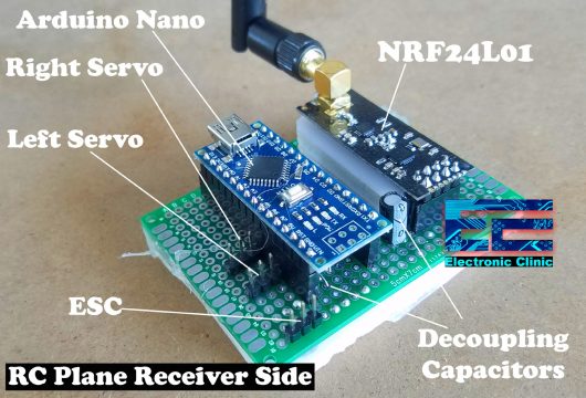
This is the receiver side consists of the Arduino Nano, NRF24L01 Transceiver Module, decoupling capacitors each one 10uf, and male headers for connecting the ESC, and two Servo Motors. This receiver-side circuit will be connected with the 30A speed controller, a 1000KV brushless DC motor, and 11.1V 2200mAh Lipo Battery Pack. I will explain the connections in the circuit diagram.
The Transmitter side circuit is already given above which consists of the same NRF24L01 Transceiver module, Arduino, a pushbutton, and three potentiometers, which are used for controlling the speed, Left Right, and Up-Down movement.
If you want to make 5 to 15Km Long range RC plane then you can read my previous article based on the 15Km Lora Transceiver modules by the Reyax Technologies.
In this tutorial, we will go through all the steps,
- Assembling the SU-27 RC Plane Parts
- The RC Plane Transmitter and Receiver circuit diagrams complete explanation
- Transmitter and Receiver side code explanation and finally
- Testing
Without any further delay let’s get started!!!
The components and tools used in this project can be purchased from Amazon, the components Purchase links are given below:
1000KV Brushless Motor, 30A Speed controller, and Propellers
4-Hole Nylon Pin Control Horns
Balsa Wood Sheets for RC Airplane
*Please Note: These are affiliate links. I may make a commission if you buy the components through these links. I would appreciate your support in this way!
RC Plane Transmitter Circuit Diagram:
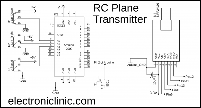
The connections on the Transmitter side are very simple. The VCC and GND pins of the NRF24L01 Transceiver module are connected with the Arduino’s 3.3V and Ground pins. A decoupling capacitor of 10uf is connected between the power supply pins. For the best performance, you can use a dedicated 3.3V power supply. For the 3.3V regulated power supply, you can use the AMS1117 voltage regulator. The CE pin is connected with the Arduino’s pin number 9, the CSN pin is connected with pin 10, SCK is connected with Pin 13, MOSI is connected with Pin 11, and finally, the MISO pin of the NRF24L01 is connected with the Arduino’s pin number 12.
A pushbutton is connected between the ground and pin number 2 of the Arduino.
The left and right legs of all the three potentiometers are connected with the Arduino’s 5 volts and ground, while the middle legs are connected with the Arduino’s analog pins A0, A1, and A3. So, that’s all about the Transmitter circuit diagram, now let’s have a look at the receiver circuit diagram.
RC Plane Receiver Circuit Diagram:

The NRF24L01 Transceiver module connections with the Arduino remains the same. Three wires of the 1000KV Brushless Motor are connected with the 30A speed controller. The yellow wire should be connected with the middle wire of the speed controller, while the red and black wires are connected with the other two wires of the speed controller, if the brushless motor rotates in the wrong direction, you can simply interchange these two wires. On the other side of the speed controller, we have a total of 5 wires. The Red and Black wires are the Power supply wires and these should be connected with the Lipo battery pack Red and Black wires.
The black and red wires are connected with the three male headers and also with the Vin and ground pin of the Arduino Nano. This 5V is used to power up all the electronics. The white wire is connected with the Arduino’s pin number 3. Through this wire, we control the speed of the brushless DC motor. The signal wires of both the Servo motors are connected with the Arduino’s pins 5 and 6.
You can see a jumper is connected between the reset pin and pin number 8. While working on the NRF24L01 Transceiver modules, you will notice one prominent thing that is the connection is lost. If the receiver’s wireless connection with the Transmitter is lost for 2 seconds the Arduino will automatically reset, the time duration can be changed in the programming. While uploading the program make sure you remove the jumper cap otherwise the program won’t upload. After uploading the code you can place the jumper cap. So, that’s all about the receiver circuit diagram.
Transmitter and Receiver circuits making:
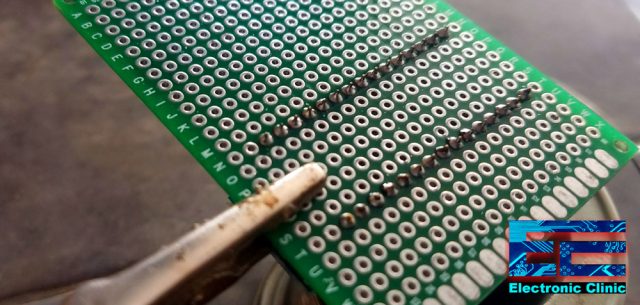
I started off by soldering the components on a Vero Board. Very soon I will be making the PCBs. I always first test my circuit connections on a Vero Board, analyze the performance, and then later make the PCBs. In an hour or so I was done with the soldering. Finally, before powering up the circuits I tested both the circuits to check if there was any short circuit. Then I completed the connections as per the circuit diagrams.
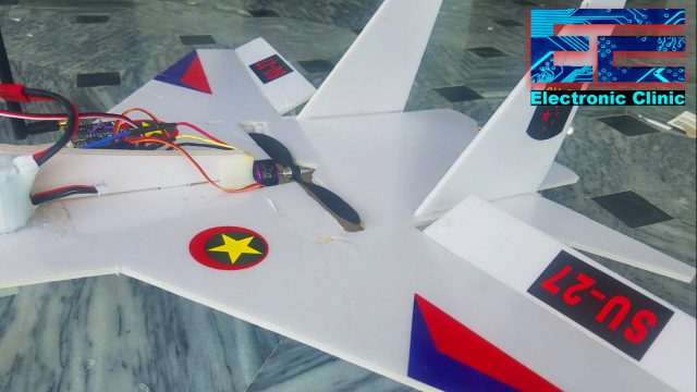
Transmitter Side of the RC Plane:
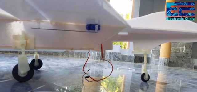
Receiver Side of the RC Plane:

After completing all my connections, finally, I was ready to start programming.
RC Plane Arduino Programming:
The SU-27 RC Jet plane is based on two programs. One program is written for the Transmitter side while the other program is written for the Receiver side. Before you start the programming, first of all, make sure that you download all the necessary libraries used in this project.
RC Plane Transmitter Side Arduino Programming:
|
1 2 3 4 5 6 7 8 9 10 11 12 13 14 15 16 17 18 19 20 21 22 23 24 25 26 27 28 29 30 31 32 33 34 35 36 37 38 39 40 41 42 43 44 45 46 47 48 49 50 51 52 53 54 55 56 57 58 59 60 61 62 63 64 65 66 67 68 69 70 71 72 73 74 75 76 77 78 79 80 81 82 83 84 |
//RC Plane //Transmitter coding for the nrf24L01 radio transceiver. //https://www.electroniclinic.com/ /* pins connections vcc 3.3 gnd gnd ce pin9 scn pin10 sck pin13 mosi pin11 moso pin12 */ #include <SPI.h> #include <nRF24L01.h> #include <RF24.h> #define CE_PIN 9 #define CSN_PIN 10 #define JOYSTICK_X A0 #define JOYSTICK_Y A1 #define PushButton 2 // this push button will be used to activate the lef right control or the up down control const uint64_t pipe = 0xE8E8F0F0E1LL; RF24 radio(CE_PIN, CSN_PIN); byte data[6]; // depending on the number of sensors used int j1flag = 0; // joystick1 button flag void setup() { Serial.begin(9600); radio.begin(); radio.openWritingPipe(pipe); pinMode(JOYSTICK_X,INPUT); pinMode(JOYSTICK_Y, INPUT); pinMode(PushButton,INPUT_PULLUP); pinMode(A2, INPUT); // default values data[0] = 127; // JOYSTICK1 VRX data[1] = 127; // JOYSTICK1 VRY data[2] = 1; // jOYSTICK1 BUTTON data[3] = 1; // SpeedPot } void loop() { data[0] = map(analogRead(JOYSTICK_X), 0, 1023, 0, 255); // joystick1 VRx data[1] = map(analogRead(JOYSTICK_Y), 0, 1023, 0, 255); // Joystick1 VRy if(digitalRead(PushButton) == LOW) { data[2] = 1; } if(digitalRead(PushButton) == HIGH) { data[2] = 0; } data[3] = map(analogRead(A2),0 , 1023, 0, 255); //Serial.println(data[1]); //Serial.println("Data"); //Serial.println(data[0]); // up down //Serial.println(data[1]); // left right //Serial.println(data[2]); // button //Serial.println(data[3]); // speed //delay(300); radio.write( data, sizeof(data) ); } void resetData() { } |
RC Plane Transmitter Side Code Explanation:
/*
Following are the connections of the NRF24L01 Transceiver module with the Arduino Uno or Arduino Nano.
vcc 3.3
gnd gnd
ce pin9
scn pin10
sck pin13
mosi pin11
moso pin12
I started off by adding the libraries.
#include <SPI.h>
#include <nRF24L01.h>
#include <RF24.h>
Next I defined pins for the CE, CSN, the joystick, and pushbutton. Instead of using the joystick, I will be using the potentiometers. It really doesn’t matter if you use the joystick or potentiometers, it will have no effect on the programming.
#define CE_PIN 9
#define CSN_PIN 10
#define JOYSTICK_X A0
#define JOYSTICK_Y A1
#define PushButton 2 // this push button will be used to activate the left-right control or the up-down control
const uint64_t pipe = 0xE8E8F0F0E1LL; // a unique address, this way no other use can connect with your NRF24L01 Transceiver module. So, don’t share this with anyone. Anyways you can always change this. Make sure you use the same address on both sides.
RF24 radio(CE_PIN, CSN_PIN);
Data is an array of the type byte, current you can send data from six different sensors. You can increase this number if you want to use more buttons and sensors.
byte data[6]; // depending on the number of sensors used
int j1flag = 0; // joystick1 button flag
The void setup() functions is quite clear, there is nothing to explain, I am sure you already know about these basic functions and why they are used.
void setup()
{
Serial.begin(9600);
radio.begin();
radio.openWritingPipe(pipe);
pinMode(JOYSTICK_X,INPUT);
pinMode(JOYSTICK_Y, INPUT);
pinMode(PushButton,INPUT_PULLUP);
pinMode(A2, INPUT);
// default values
data[0] = 127; // JOYSTICK1 VRX
data[1] = 127; // JOYSTICK1 VRY
data[2] = 1; // jOYSTICK1 BUTTON
data[3] = 1; // SpeedPot
}
void loop()
{
First we read data from the joystick VRx and VRy pins or the two potentiometers, and then map the data and define the minimum and maximum values, currently the values are limit between the 0 and 255. After mapping the values, then these are stored in the array data at locations 0 and 1.
data[0] = map(analogRead(JOYSTICK_X), 0, 1023, 0, 255); // joystick1 VRx
data[1] = map(analogRead(JOYSTICK_Y), 0, 1023, 0, 255); // Joystick1 VRy
The pushbutton, as I said earlier is used for the transfer of control. So if the button is pressed a value of 1 is stored in the array at location 2, and if the button is not pressed then a value of 0 is stored in the same location. From the 1 and 0 values, the receiver knows if the user has pressed the pushbutton.
if(digitalRead(PushButton) == LOW)
{
data[2] = 1;
}
if(digitalRead(PushButton) == HIGH)
{
data[2] = 0;
}
The third potentiometer is used for controlling the speed of the Brushless DC Motor, the value is mapped and is stored in the array data at location 3.
data[3] = map(analogRead(A2),0 , 1023, 0, 255);
you can uncomment the following instructions for debugging purposes if you want to check if everything is working the same way as you want.
//Serial.println(data[1]);
//Serial.println(“Data”);
//Serial.println(data[0]); // up down
//Serial.println(data[1]); // left right
//Serial.println(data[2]); // button
//Serial.println(data[3]); // speed
//delay(300);
Finally, the complete array consisting of the values from potentiometers and Pushbutton is send to the Receiver.
radio.write( data, sizeof(data) );
}
void resetData()
{
}
RC Plane Receiver Side Arduino Programming:
|
1 2 3 4 5 6 7 8 9 10 11 12 13 14 15 16 17 18 19 20 21 22 23 24 25 26 27 28 29 30 31 32 33 34 35 36 37 38 39 40 41 42 43 44 45 46 47 48 49 50 51 52 53 54 55 56 57 58 59 60 61 62 63 64 65 66 67 68 69 70 71 72 73 74 75 76 77 78 79 80 81 82 83 84 85 86 87 88 89 90 91 92 93 94 95 96 97 98 99 100 101 102 103 104 105 106 107 108 109 110 111 112 113 114 115 116 117 118 119 120 121 122 123 124 125 126 127 128 129 130 131 132 133 134 135 136 |
//Receiver coding for the nrf24L01 radio transceiver. /* pins connections vcc 3.3 gnd gnd ce pin9 scn pin10 sck pin13 mosi pin11 miso pin12 */ #include <SPI.h> #include <Servo.h> #include <nRF24L01.h> #include <RF24.h> #define CE_PIN 9 #define CSN_PIN 10 Servo servoLeft; Servo servoRight; Servo BMotor; int B_Motor = 3; int LeftServo = 5; int RightServo = 6; int ud_data; // up down data int lr_data; // left right data int speed_data; // brushless motor speed data int receiver_reset = 8; /* the purpose of of defining the receiver_reset pin is to programmly reset the arduino, While using the NRF24 Transceiver modules * you will notice one most prominent issue, which is the connection is lost, Some guys are using the technique of using the default values * and then keep waiting until the connection is established again, this is not a good idea. * After testing a series of tests, i found out, reseting the arduino is the best option. if the connection is lost lets say for 2 seconds then the arduino * resets automatically. After doing this thing i didn't notice any abnormal code execution. * */ const uint64_t pipe = 0xE8E8F0F0E1LL; RF24 radio(CE_PIN, CSN_PIN); byte data[6]; // depending on the number of sensors used unsigned long lastReceiveTime = 0; unsigned long currentTime = 0; int secs = 0; void setup() { digitalWrite(receiver_reset, HIGH); delay(200); pinMode(receiver_reset, OUTPUT); Serial.begin(9600); pinMode(B_Motor, OUTPUT); servoLeft.attach(LeftServo); // pin 5 servoRight.attach(RightServo); // pin 6 BMotor.attach(B_Motor); Serial.println("Nrf24L01 Receiver Starting"); radio.begin(); radio.openReadingPipe(1,pipe); radio.startListening(); resetData(); //default values servoLeft.write(90); servoRight.write(90); BMotor.write(0); } void loop() { if ( radio.available() ) { bool done = false; while (!done) { done = radio.read( data, sizeof(data) ); lastReceiveTime = millis(); // At this moment we have received the data secs = 0; // updown if (data[2] == 1) { ud_data = map(data[0], 0 , 255, 0 , 180); servoLeft.write(ud_data); servoRight.write(ud_data); delay(50); } // Left Right if (data[2] == 0) { servoLeft.write(map(data[1], 0,255,0, 180)); servoRight.write(map(data[1], 0,255,180, 0)); delay(50); } speed_data = map(data[3],0, 255, 1000, 2000); BMotor.writeMicroseconds(speed_data); delay(50); } } else { currentTime = millis(); if ( currentTime - lastReceiveTime > 1000 ) { // If current time is more then 1 second since we have recived the last data, that means we have lost connection resetData(); // If connection is lost, reset the data. It prevents unwanted behavior, for example if a drone has a throttle up and we lose connection, it can keep flying unless we reset the values // secs = secs + 1; if(secs >= 2) { digitalWrite( receiver_reset, LOW); secs = 0; } } } } void resetData() { // we are going to place our default code over here. Serial.println("Connection Lost"); BMotor.writeMicroseconds(1500); } |
RC Plane Receiver Side Code Explanation:
/*
pins connections on the receiver side remains the same.
vcc 3.3
gnd gnd
ce pin9
scn pin10
sck pin13
mosi pin11
miso pin12
*/
On the Receiver side, as you can see I added one more library for the Servo motors.
#include <SPI.h>
#include <Servo.h>
#include <nRF24L01.h>
#include <RF24.h>
#define CE_PIN 9
#define CSN_PIN 10
Servo servoLeft;
Servo servoRight;
Servo BMotor;
Defined pins for the Brushless motor, Left Servo Motor, and Right Servo Motor.
int B_Motor = 3;
int LeftServo = 5;
int RightServo = 6;
defined variables for storing the data which is received from the transmitter.
int ud_data; // up down data
int lr_data; // left right data
int speed_data; // brushless motor speed data
int receiver_reset = 8;
/* the purpose of defining the receiver_reset pin is to programmly reset the Arduino, While using the NRF24 Transceiver modules, you will notice one most prominent issue, which is, the connection is lost, Some guys are using the technique of using the default values and then keep waiting until the connection is established again, this is not a good idea. After performing a series of tests, I found out, resetting the Arduino is the best option. If the connection is lost let’s say for 2 seconds then the Arduino resets automatically. After doing this thing I didn’t notice any abnormal code execution.
*
*/
const uint64_t pipe = 0xE8E8F0F0E1LL;
RF24 radio(CE_PIN, CSN_PIN);
byte data[6]; // depending on the number of sensors used
defined some variables for the timer.
unsigned long lastReceiveTime = 0;
unsigned long currentTime = 0;
int secs = 0;
void setup()
{
digitalWrite(receiver_reset, HIGH);
delay(200);
pinMode(receiver_reset, OUTPUT);
Serial.begin(9600);
pinMode(B_Motor, OUTPUT);
servoLeft.attach(LeftServo); // pin 5
servoRight.attach(RightServo); // pin 6
BMotor.attach(B_Motor);
Serial.println(“Nrf24L01 Receiver Starting”);
radio.begin();
radio.openReadingPipe(1,pipe);
radio.startListening();
resetData();
//default values
servoLeft.write(90);
servoRight.write(90);
BMotor.write(0);
}
void loop()
{
The purpose of the following if condition is to check, if the receiver has received any data from the transmitter. We simply set the lastReceiveTime to the current millis, and make secs “seconds” equal to zero.
if ( radio.available() )
{
bool done = false;
while (!done)
{
done = radio.read( data, sizeof(data) );
lastReceiveTime = millis(); // At this moment we have received the data
secs = 0;
// updown
if (data[2] == 1) // if the pushbutton is not pressed
{
ud_data = map(data[0], 0 , 255, 0 , 180);
servoLeft.write(ud_data);
servoRight.write(ud_data);
delay(50);
}
// Left Right
if (data[2] == 0) // if the push button is pressed
{
servoLeft.write(map(data[1], 0,255,0, 180));
servoRight.write(map(data[1], 0,255,180, 0));
delay(50);
}
Control the speed of brushless dc motor
speed_data = map(data[3],0, 255, 1000, 2000);
BMotor.writeMicroseconds(speed_data);
delay(50);
}
}
else
{
currentTime = millis();
if ( currentTime – lastReceiveTime > 1000 ) { // If current time is more than 1 second since we have received the last data, that means we have lost connection
resetData(); // If connection is lost, reset the data. It prevents unwanted behavior, for example if a drone has a throttle up and we lose connection, it can keep flying unless we reset the values
//
secs = secs + 1;
if(secs >= 2) // if the connection remains lost, then we reset the Arduino,
{
digitalWrite( receiver_reset, LOW);
secs = 0;
}
}
}
}
void resetData()
{
// we are going to place our default code over here.
Serial.println(“Connection Lost”);
BMotor.writeMicroseconds(1500);
}
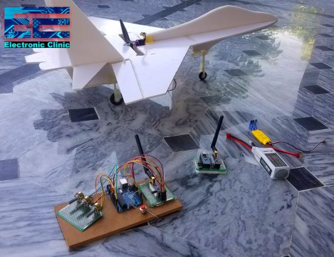
RC Plane Transmitter and Receiver Testing:
After, writing the code, I uploaded my programs, performed my initial tests, while the servo motors were connected. I fixed the issues, made some changes. The above programs are after fixing all the bugs. So, after I was done with the testing. Then I started with assembling the SU-27 RC Plane.
SU-27 RC Plane Assembling:
For the detailed step by step explanation watch video given at the end of this article.
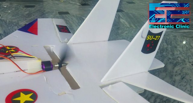
After assembling the parts, I fixed the 1000KV motor and the two Servo Motors, one on the left side and the other one the Right side of the RC Jet Plane.
Then I fixed the Receiver circuit, Speed Controller, 11.1V 2200mAh Lipo Battery Pack using the Hot Glue.
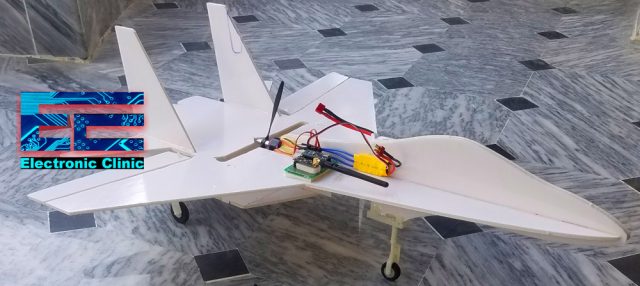
At this point, my RC jet Plane was ready for the first test. I connected the power supply wires, and double-checked my connections. I made sure there was no lose connection.
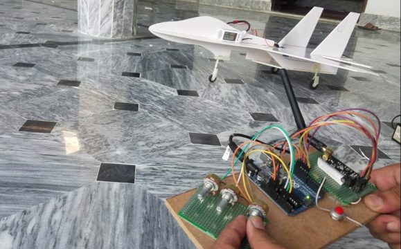
I was able to control the speed of the Brushless DC motor using the potentiometer. This was a successful test.
Then I tested the Servo motors, I was able to control the Up Down and Left-Right Movement. After making sure that everything is just fine. Then I continued with the stickers, and my RC Plane was ready for the Fly.

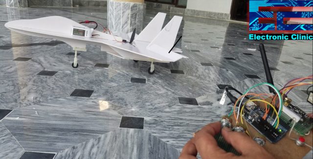
After fixing the stickers, again I check everything
I was able to control the Up_Down movement using the servo motors.
I was also able to control the speed of the Brushless DC motor. It was a real fun while working on this project.
I hope you have learned something new from this project. If you have any questions regarding this project or any other project let me know in a comment.
Watch Video Tutorial:

Discover more from Electronic Clinic
Subscribe to get the latest posts sent to your email.


exit status 1
Error compiling for board Arduino Nano.
C:\Users\Ahsan\AppData\Local\Temp\arduino_modified_sketch_338638\sketch_mar26a.ino: In function ‘void loop()’:
sketch_mar26a:84:40: error: void value not ignored as it ought to be
done = radio.read( data, sizeof(data) );
Multiple libraries were found for “nRF24L01.h”
Used: C:\Users\Ahsan\Documents\Arduino\libraries\RF24
Not used: C:\Users\Ahsan\Documents\Arduino\libraries\RF24-master
exit status 1
void value not ignored as it ought to be
This report would have more information with
“Show verbose output during compilation”
option enabled in File -> Preferences.
Hi Engr, Fahad,
I have following questions. Please answer these.
In the X’mitter circuit diagram you have specified Arduino 2009 but in the part list you have specified: Arduino Uno and Arduino Nano. Which one should we be using.
For motors you have specified 2 in the part list: i) 1000KV Brushless Motor, 30A Speed controller, and Propellers, and ii) Top Brushless Motors. Which one should we be using.
Would be grateful if you could answer.
Thanks
Raj
error: void value not ignored as it ought to be done = radio.read( data, sizeof(data) );
Could you please repost the video as I am following this tutorial but it is hard for me to assemble the kit
Hello, it is possible to use Arduino Uno in the receiver
Hello: It is possible to use Arduino Uno for the receiver and transmitter without changing the codes