Raspberry Pi GPIO Pins and how to use them in programming
Last Updated on August 3, 2022 by Engr. Shahzada Fahad
Table of Contents
Raspberry Pi GPIO access
To read or change the status of the GPIO pins, you can use the Python module RPi.GPIO with the version 0.5.11 of the module presented here, you can read or modify individual pins as well as you can use the software pulse width modulation. Serial interfaces are currently supported, Bus systems SPI and I2C, hardware PWM as well as the reading of 1-wire temperature sensors. All examples in this section have an extremely simple connection with the Raspberry Pi . To explain how to use Raspberry Pi GPIO pins let’s start with the following circuit diagram.
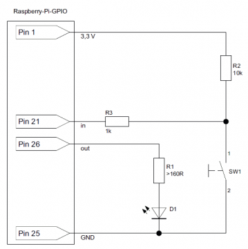
Pin 1 is the 3.3V pin, you can use this to power up your electronics. In this example project the 3.3Volts are connected with the Push button “SW1” through a 10K ohm resistor R2, this is basically a Pullup resistor. When the SW1 or Pushbutton is pressed it gives LOW or GND as the signal to the Pin26 which is used as in input. While when the SW1 is opened then it gives 3.3V or HIGH signal as the input to the Pin21 of the Raspberry Pi. The resistor R3 which is 1K ohm simply controls the current flow. The Raspberry Pi GPIO PIN 26 is used as the output and is connected with the LED through a 160 ohm resistor R1. While the GPIO Pin 25 of the Raspberry Pi is GND which is connected with the cathode side of the LED and also with the Push Button.
Amazon Purchase Links:
Wireless Keyboard and Mouse for raspberry pi:
Night vision Camera for Raspberry Pi:
Oled HDMI touch display for raspberry pi:
Other Tools and Components:
Super Starter kit for Beginners
PCB small portable drill machines
*Please Note: These are affiliate links. I may make a commission if you buy the components through these links. I would appreciate your support in this way!
Read and modify GPIO pins When importing the module, it is useful to define an abbreviation with as gpio, so that RPi.GPIO does not have to be preceded when accessing each function. Before accessing the Raspberry Pi GPIOs for the first time, you must determine whether to use the internal Raspberry Pi GPIO numbers of the BCM CPU or the pin numbering of the J8 headers. To do this, perform one of the following two setmode functions. All examples in this article use the pin numbers of the J8 header or the P1 header if you are using an old Raspberry Pi (model A/B version 1).
|
1 2 3 4 5 |
import RPi . GPIO as gpio Gpio. setmode ( gpio . BOARD ) - Pin - Numbers of the J8 - Header Gpio. setmode ( gpio . BCM ) or Broadcom -GPIO – Numbers |
Finally, you need to set up each GPIO pin that you want to use in your script. To do this, you specify with setup whether the pin is used for input or output. Allowed Settings are IN and OUT.
|
1 2 3 4 5 6 7 8 9 |
Gpio. setmode ( gpio .BOARD ) - Pin - Numbers of the P1 /J8 - Header Gpio. setup (26 , gpio .OUT ) - Pin 26 for data output Gpio. setup (21 , gpio .IN ) - Pin 21 for data entry Optionally, you can also specify the start state for outputs (HIGH or LOW). gpio. setup (26, gpio .OUT, gpio. HIGH) |
The setup function may give a warning if another program also uses GPIO pins: RuntimeWarning: This channel is already in use, continuing anyway. The program continues despite the warning, especially since the warning is often just an indication that another Python script is doing the required has forgotten the cleanup call (see below). If necessary, you can Suppress the warning by inserting the following line before the setup call:
|
1 2 3 |
gpio. setwarnings (False) # suppress warnings gpio. set up (...) |
To determine how a Raspberry Pi GPIO pin was programmed, evaluate the function gpio_function. In addition to gpio.IN and .OUT, it can also display the results .SPI, .I2C, Return .SERIAL or .UNKNOWN.
After this preparatory work you can finally change the Raspberry PI GPIOs or read out, depending on whether these have been set for output or input. To change the initial state of the LED, use the following function:
|
1 2 3 4 5 6 7 8 9 10 11 12 13 14 15 16 17 18 19 20 21 22 23 24 25 26 27 28 29 |
gpio. output (26, gpio. HIGH) # Set GPIO to high ... gpio. output (26, gpio. LOW) # Set GPIO to low For signal inputs, the input function returns the current status 0 or 1 (corresponds to LOW or False or HIGH or True): status = gpio. input (21) try: # Carry out initialization work import RPi. GPIO as gpio, sys gpio. setmode (gpio. BOARD) # P1 / J8 -Pin - numbers gpio. setup (26, gpio. OUT) # Pin 26 for data output ... except RuntimeError: print ('This script must be executed with sudo.') sys. exit () |
At the end of the program, you should restore or release all Raspberry Pi GPIO pins used by your script. To do this, you usually just run cleanup. finally make sure that cleanup is executed even if there is an error in the script:
|
1 2 3 4 5 6 7 |
try: gpio code finally: gpio. cleanup () |
If you do not want to release all the Raspberry Pi GPIO pins but only a selected pin, depending on the setmode setting, pass the relevant pin or GPIO number:
gpio. cleanup (n)
Buttons and switches:
How can a Python script monitor the state of the button? A simple and the obvious solution looks like this:
|
1 2 3 4 5 6 7 |
while True: input = gpio. input (21) print ('State:' + str (input)) time. sleep (0.05) |
In a loop it is determined approx. 20 times per second whether the button is pressed or not. Monitoring of signal states through a loop but is seldom an optimal concept. When the sleep time is short, the program causes a lot unnecessary CPU load; if you specify a longer time, it increases Response time of the program, and in the worst case it overlooks a short one it is much smarter to formulate the Python program that it simply waits for a signal change and only then becomes active again. The RPi.GPIO module offers three functions for this purpose, which ensures programming and also use CPU resources sparingly:
- wait_for_edge waits for a change of state of a GPIO pin. Here you are waiting for a falling or a rising signal level or also on both. Until the level change occurs, the program does nothing and uses up only negligibly few CPU cycles.
|
1 2 3 4 5 |
gpio. wait_for_edge (n, gpio. RISING) gpio. wait_for_edge (n, gpio. FALLING) gpio. wait_for_edge (n, gpio. BOTH) |
- With add_event_detect you can have background monitoring of a GPIO pin. You can later use event_detected to determine whether the expected Event has occurred in the meantime. event_detected can be repeated. It always indicates whether another event has occurred since the last call has arrived. event_detected is particularly well suited to in the main loop of Games or user interfaces regularly query GPIO inputs.
|
1 2 3 4 5 6 7 |
gpio. add_event_detect (n, gpio. FALLING) # do other things ... if gpio. event_detected (n): # respond to the event |
If you want to stop the signal monitoring before the end of the program, run Select remove_event_detect (n).
- Last but not least, you can use add_event_callback to create a so-called callback. Specify the function that is to be called automatically each time a level change occurs. add_event_callback sets a previous add_event_detect call ahead.
parameter is passed to the callback function which, depending on the set mode, sets the Contains pin or GPIO number. The following code does the callback function automatically called every time during the waiting time of 10 seconds the button is pressed or released again:
|
1 2 3 4 5 6 7 8 9 |
def myCallback (n): print ('Level change for pin', n, 'detected.') gpio. add_event_detect (21, gpio. BOTH) gpio. add_event_callback (21, myCallback) time. sleep (10) |
You can optionally use add_event_detect as the third parameter bouncetime = n and thus the minimum time between two level changes specify in milliseconds. This should avoid multiple events, when switches or buttons bounce. Unfortunately, our tests have bouncetime works very unreliably. Application examples for add_event_callback.
Software PWM
The RPi.GPIO module supports software-controlled Pulse Width Modulation (PWM), i.e. the regular switching on and off of a GPIO pin in a given Frequency. To do this, first create a PWM object, using the desired frequency Specify in Hertz (maximum 1023 Hertz). You can then use the PWM begin with start and end with stop. Pass a Parameter between 0 and 100 that specifies what percentage of a period the signal output should be switched to high.
The following code causes the light emitting diode connected to GPIO pin 26 turns on and off twice per second. Within a period of oscillation the LED is 50% on and 50% off.
|
1 2 3 4 5 6 7 8 9 |
gpio. setup (26, gpio. OUT) # LED on GPIO pin 26 pwm = gpio .PWM (26, 2) # Frequency: 2 Hertz pwm. start (50) # Duty: 50% time. sleep (10) pwm. stop () |
Both the frequency and the percentage of the high signal can be changed at any time the ChangeFrequency and ChangeDutyCycle methods are used. The following Settings cause the LED to light up briefly every two seconds:
|
1 2 3 |
pwm. ChangeFrequency (0.5) # Frequency: 0.5 Hertz pwm. DutyCycle (10) # Duty: 10% |
Find out the version of the Raspberry Pi model
If you want to know which RPi.GPIO version you are dealing with or You evaluate the VERSION variable on which version of the Raspberry Pi your script is running and RPI_INFO. Note that those supported by older RPi.GPIO versions Variable RPI_REVISION is considered obsolete and should no longer be used! The following issues were created on a Raspberry Pi 2, Model B:
|
1 2 3 4 5 6 7 8 9 10 11 12 13 14 15 |
print ('RPi.GPIO - Version', gpio. VERSION) RPi .GPIO - version 0.5.11 print (gpio. RPI_INFO) {'P1_REVISION': 3, 'RAM': '1024 M', 'REVISION': 'a01041', 'TYPE': 'Pi2 Model B', 'PROCESSOR': 'BCM2836', 'MANUFACTURER': 'Sony'} print (GPIO. RPI_INFO ['TYPE']) Pi2 Model B |
Discover more from Electronic Clinic
Subscribe to get the latest posts sent to your email.