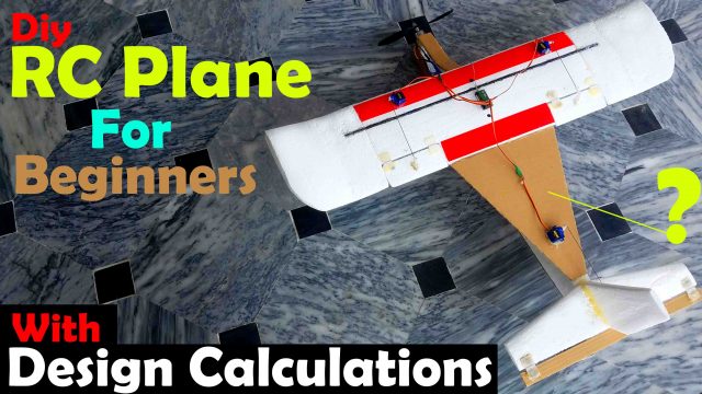
RC Plane Designing Calculations, Making, and Flight Test
Table of Contents
RC Plane Designing, Description:
RC Plane Designing, Making, and Flight Test- In my previous tutorial, I explained how to build an RC Paper airplane using a readymade template, how to set up the Flysky FS i6 transmitter, and I also shared the flight test results.
I learned a lot of new things while working on the RC paper airplane. As this was my first time flying an RC airplane I was very happy, but still there was something missing, I wasn’t feeling that inner happiness. As an engineer, I am supposed to design my own RC airplane rather than using a readymade template. So, I started to study some research papers, watched a lot of videos, and finally, I was able to start my own RC Plane designing.
So, in this tutorial, you will learn how to design and build your own RC airplane. I will explain in detail how to calculate each and every part of the RC plane so that you can make smaller or bigger RC Airplanes. It really doesn’t matter whether you are using Balsa wood, Styrofoam, or other types of foam board sheets, or 3d printed parts, the calculations will remain exactly the same.
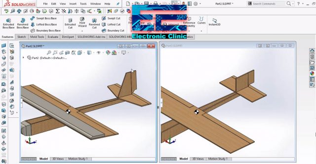
There are important things which I will also explain with the help of these 3d models, you can see this one is normal and to the other one the aerodynamics is applied. When you cut parts of the model it really affects the aspect ratio and interns it affects the RC plane stability. So, I will explain in detail how to keep the same aspect ratio even if you cut some parts of the RC Airplane.
Anyhow, before designing and making the bigger RC airplane I started with the micro version of the airplane to test my calculations and I was pretty happy with the results. Finally, I did calculations for this big RC plane. Don’t be afraid if I am using two brushless motors it has nothing to do with the basic RC plane designing. The reason I am using two brushless motors is that my RC plane is made of Balsa wood and it’s a little heavier. You can make the lighter version of the same RC airplane using foam board sheets. This way you can use a single brushless motor.
Different parts of the RC Plane:
First, let’s take a look at the different parts of the RC airplane and then we will start the RC Plane design calculations.
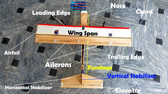
Chord Length is the width of the Wing.
The Length of the Wing is referred to as the Wingspan.
The Wing edge on the nose side is the leading edge of the Wing.
The Wing edge on the tail side is the trailing edge of the wing.
The control surfaces of the Wing are called as the Ailerons.
This is the Fuselage.
This is the horizontal stabilizer.
The control surface of the Stabilizer is called as the Elevator.
This is the Vertical stabilizer.
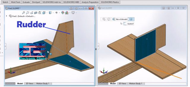
With the vertical stabilizer there is another part which is called Rudder. I have included this in the design calculations but I am not using this in this model. If you want you can add the rudder to your RC plane. I will use Rudder for controlling the left and right movements.
After you know about the different parts, now, it’s time to start with the calculations.
Without any further delay let’s get started!!!
Amazon Purchase Links:
Best RC planes and Accessories
Flysky FS i6 Transmitter and Receiver
1000KV Brushless Motor, 30A Speed controller, and Propellers
4-Hole Nylon Pin Control Horns
Balsa Wood Sheets for RC Airplane
Other Tools and Components if you need:
Super Starter kit for Beginners
PCB small portable drill machines
*Please Note: These are affiliate links. I may make a commission if you buy the components through these links. I would appreciate your support in this way!
RC Plane Designing Calculation:
Chord Length:
While designing an RC plane, we usually start by fixing the Chord length or the Wingspan. Let’s start by fixing the chord length. So,
Chord length “C” = 8 inches
Airfoil Thickness, Flat bottom type:
Airfoil thickness should be 12 to 15% of the chord length. So,
Airfoil thickness = 12% X 8inches = .96 inches
Airfoil thickness = .96 inches
If you take a look at my RC plane, you will see I didn’t add Airfoil, I did this on purpose. I want to check what happens when the airfoil is not added. After performing the initial tests then obviously I will add the Airfoil. So, anyhow the Airfoil thickness is .96 inches, this is close to 1inch, so you can select 1inch or you can proceed with this value.
Wingspan:
There are a few thumb rules which are used in aero modeling. So, according to these rules the Wingspan should be 5 to 6 times of the chord length. As, our chord length is 8 inches. So
Wingspan = 8 x 5 = 40 inches
Wing Length = Wingspan = 40 inches
Total Wing Area for Rectangular type Wing:
As we are using a rectangular type wing, so its area can be calculated by multiplying the wingspan with the chord length.
Wing Area = Wingspan X chord length = 40 X 8 = 320 square inches
Wing Area = 320 square inches
Aspect Ratio:
The Aspect ratio determines the gliding performance of the RC plane. Wingspan is directly proportional to the aspect ratio. So, as the wingspan increases your aspect ratio also increases. That is as the wingspan increases the gliding performance of your wing increases. So, for this particular RC plane the Aspect ratio is 5.
Aspect Ratio = (Wingspan) 2 / Wing area
Aspect Ratio = (Wingspan X Wingspan) / (Wingspan X Chord length)
Aspect Ratio = Wingspan / chord length
Aspect Ratio = 40 inches / 8 inches
Aspect Ratio = 5
Fuselage Length:
Fuselage should be 75% of the Wingspan. So,
Fuselage Length = 75% X 40 = 30 inches
Fuselage Length = 30 inches
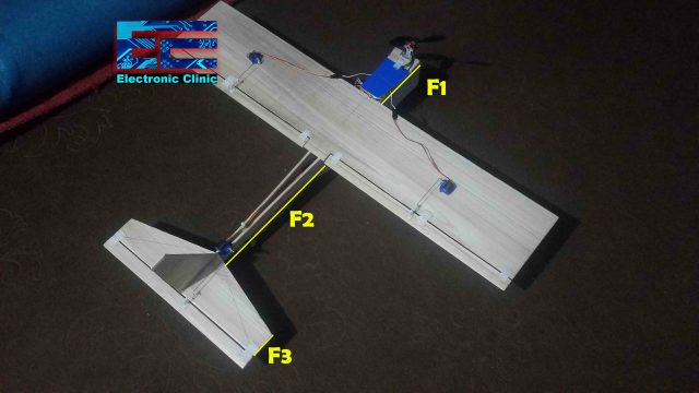
The fuselage is further divided into three parts F1, F2, and F3. F1 is from the start to the leading edge of the wing. F1 should be 20% of the fuselage length, this is called the nose length. And F2 which is the tail length from wing trailing edge to leading edge of the horizontal stabilizer and it should be 40% of the fuselage length. F3 is the remaining length of the fuselage and this is the width of the horizontal Stabilizer. So, the nose length is 6 inches, the tail length is 12 inches, and the horizontal stabilizer width is 4 inches.
F1 = Nose Length:
F1 = 20% X 30 inches = 6 inches
Nose length = F1 = 6 inches
Tail length:
Tail length = F2 = 40% X 30 inches = 12 inches
Tail length = F2 = 12 inches
So fuselage total length = 6 inches nose length + 8 inches chord length + 12 inches trailing edge to the stabilizer leading edge = 26 inches
While the calculated value was 30 inches. So 30 – 26 = 4 inches
So, these 4 inches is the Stabilizer width.
Stabilizer Width = F3 = 4 inch
Fuselage Height:
The fuselage height should be 10 to 15% of the fuselage length. So,
Fuselage Height = 10% X 30 = 3 inches
Fuselage Height = 3 inches
You can play around with the Fuselage design, you can see clearly on the tail side I cut some wood, this will reduce the weight and will also improve the aerodynamics.
Sizing of the Control Surface, Ailerons:
Next on the list is the sizing of the control surface Ailerons. It should be (1/8) X chord length. This is for the strip type ailerons. So,
Aileron size = (1/8) x 8 = 1 inch
Aileron size: 1 inch
Horizontal Stabilizer Area:
The horizontal stabilizer area should be 15 to 20% of the Wing Area.
Our calculated wing area was 320 square inches, So
Wing Area = 320 square inches
Horizontal Stabilizer area = 320 X 15% = 48 square inches
Horizontal Stabilizer Length:
We know the Horizontal stabilizer width and area, so now we can easily calculate the Horizontal stabilizer length which is 12 inches.
Horizontal Stabilizer width = F3 = 4 inches
Horizontal Stabilizer Area = 48 square inches
So, for the rectangular type stabilizer
Stabilizer area = width X length
48 = 4 X length
Length = 48/4
Stabilizer Length = 12 inches
Elevator Sizing:
The Elevator area should be 20 to 30% of the horizontal stabilizer area. While we assume the elevator length is the same as the stabilizer length.
Elevator length = stabilizer length = 12 inches
Elevator area = 48 X 20% = 9.6 square inches
As, Elevator area = width X length, so, we can find the width of the elevator
9.6 = width X 12
Elevator width = .8 inches
Vertical Stabilizer:
Area of the vertical stabilizer should be 33% of the Horizontal stabilizer area. So
Vertical Stabilizer area = 33% X 48 square inches = 16 square inches
Vertical Stabilizer area = 16 square inches
Let’s keep the width same as the horizontal stabilizer width, so
Vertical Stabilizer width = 4 inches
Vertical stabilizer is as tall as its width
So
Vertical Stabilizer Height = 4 inches
Rudder Area:
Rudder area should be ½ X vertical stabilizer area. So, the rudder area is 8 square inches.
Rudder area = ( 1 / 2 ) X 15.84
Rudder area = 8 square inches
Length of the Rudder is same as the vertical stabilizer height
Height of Rudder = 4 inches
We know
Rudder area = height x width
So,
8 = 4 x Width
Rudder Width = 2 inches
Center of Gravity “CG”:
CG should be set at 25% to 33% of the Chord length from the leading edge of the Wing. Our chord length is 8 inches So, our CG is at 2 inches from the leading edge.
CG = 25% X chord length
CG = 25% X 8 inches
CG = 2 inches
Angle of Attack:
Angle of attack should be 3 to 4 degrees. For now, I didn’t add any angle of attack; because I want to check how this affects the flight.
Dihedral:
Dihedral if you want should be 2 to 3 degrees
Wing Loading:
This determines how much load your wing can take
Wing Loading = All of weight of your aircraft / wing area
320 square inches is wing area.
Micro RC Plane:
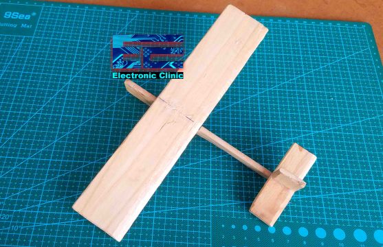
Before designing the bigger RC Plane I decided to start with the micro version of the RC plane to test my calculations. I also designed a 3d model of the same micro airplane. The reason I started with this micro version of the RC plane is to understand the effect of the CG or Center of gravity, the angle of attack, and also to test my design calculations.
I checked the gliding performance of this micro airplane without adjusting the center of gravity, which you can watch in the video given at the end of this article. You will see, when I throw this micro airplane in the air it starts rolling, because its tail heavy.
As I already explained the CG should be set at 25% to 33% of the Chord length from the leading edge of the Wing. Our chord length is 2 inches So, the center of gravity is at .5 inches from the leading edge. Currently this micro airplane is tail heavy which is not good. Let’s add some weight to the nose side. Place your fingers below the wing at about .5 inches from the leading edge of the wing. I explained this in the video. Anyhow, I adjusted the center of gravity. Remember your RC plane should be a little nose heavy, never fly an airplane with tail heavy. Tail heavy airplanes are hard to control. In the video you will clearly see the difference in flight when the center of gravity is not adjusted and when the center of gravity is adjusted. Seriously, from my personal experience, as I have been working on these RC planes, no matter how cool your RC plane is, if you have not adjusted the center of gravity, your RC airplane will crash. So, it’s considered to be the good practice, if you check the center of gravity each time you fly the RC Plane.
Anyhow, after I was done with my initial tests. It was time to start working on the bigger version of the RC airplane. I started off by designing my 3d models in Solidworks2016.
I have these two models, the one on the right side is with the actual dimensions and the one on the left side is also as per the actual dimensions but with some aerodynamics. You can clearly see the horizontal stabilizer and vertical stabilizers are modified and so airfoil is added. The surface areas are exactly the same even after cutting these portions. Now, I will explain how I did it.
You can clearly see, on the right side the horizontal stabilizer and vertical are rectangular type while the horizontal stabilizer and vertical on the left side are not rectangular. But both the models has the same surface areas.
As I explained earlier we need to keep the aspect ratios same. To keep the surface area same even after cutting portions of the vertical and horizontal stabilizers we have two options, as we cut any part, then we should accordingly increase the length or the width. In my case I kept the width constant and I changed the length. So, the vertical stabilizer in both models shares the same surface area of 16 square inches. So, you can increase or decrease the height or you can change the angle, and the surface area will change accordingly, this way you can set the aerodynamics, you can cut some portions, and at the same time you also keep the same surface area. So, if you are designing any part, I highly recommend you should use a designing software to check and confirm your design parameters.
Anyhow, after the calculations and 3d designing, the next part was to build the RC Airplane as per the values we just calculated. The building part is really simple when you have all the dimensions. In my last tutorial, I have already explained how to fix the servo motors, how to attach the ailerons, and how to setup the Flysky FS i6 Transmitter and Receiver.
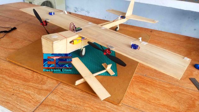
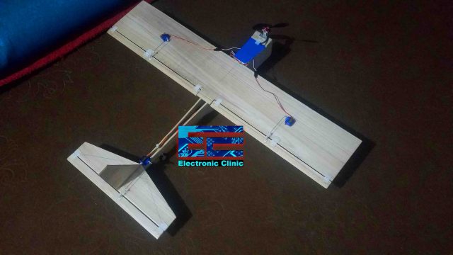
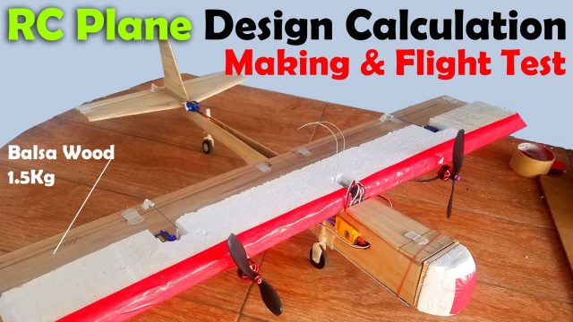
So, this is RC Plane designed as per the calculations. Just a simple model with flat nose, a brushless motor is connected to the nose of the airplane, and there is no airfoil. I tested it but the 2600kv brushless DC motor wasn’t able to lift this RC airplane. I decided to use two of these motors.
I installed two brushless motors on the leading edge of the wing. These are 2600kv brushless motors. The airfoil is not yet added.
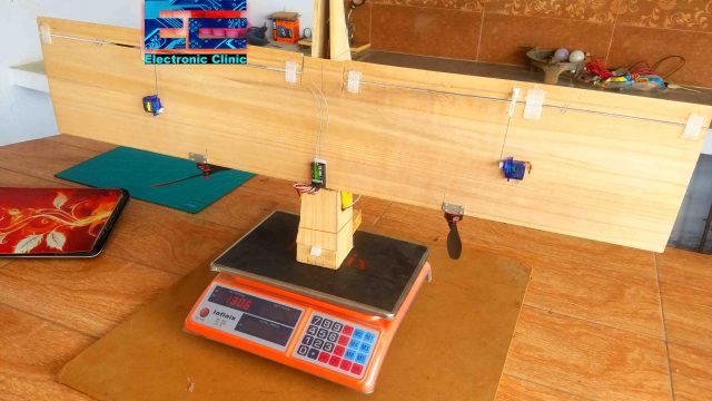
The overall weight of this RC Plane after adding all the electronics is 1306 grams. This is the reason I am using two brushless motors. These are Skywalker 2600kv brushless motors. Each motor is capable of producing over +1000 grams of thrust. As the overall weight of this RC plane is 1306 grams. So, these brushless motors with over +2kg thrust will easily lift this RC plane.
I am using 30A ESCs, 2200mAh lipo battery, 6 channels FS i6 Receiver and Transmitter, small servo motors for controlling Ailerons and the Elevator. One more thing, I am using the same channel 3 for controlling both the Brushless motors.
The last step is to check the center of gravity. You can add some weight on the nose side if it’s tail heavy. My RC plane is ready for the first take off.
I did perform some tests and the results were pretty bad as I was expecting, this was due to the lack of airfoil, and the nose front was pretty flat. So, I decided to add the airfoil and also decided to round the nose side.
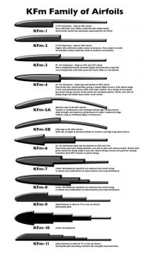
Anyhow, I selected the KFm-2 type Airfoil as this is easy to build and add more strength to the wing. Previously I did calculations for the Flat bottom type Airfoil, which of course you can use. But for now, I will continue with this KFm-2 type Airfoil. Because the KFm2 type airfoil is good for heavier models, this gives higher lift, and gives nice stability.
The KFm-2 type airfoil should be 50% of the wing chord.
As you know the wing chord is 8 inches, so 50% X 8 inches = 4 inches
Its thickness should be 7% to 9% of the chord, so,
The KFm-2 Airfoil thickness = 7% X 8 inches = .56 inches.
There is a whole family of the KFm type airfoils, you can select anyone as per your requirement.
Balsa Wood Dual Brushless Motor RC Airplane Flight Test:
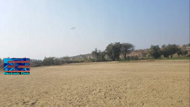
After modifying my RC airplane, once again I checked the center of gravity. So, let’s start with the final Fly test. For the flight test watch video given below. You can see the RC plane is quite stable, the KFm2 airfoil is simply amazing, All my calculations are correct, the center of gravity is perfect. The control surfaces are just cool and quite responsive. I successfully made the left turn, then the tree blocked the view, I got nervous and I pushed the stick all the way to the left, the plane rolled, it was upside down, and I crashed it. This was completely destroyed; I am a bad pilot. I was supposed to move the stick a little to the left. So, I really don’t know what to say, I just crashed it, I am really good at destroying RC planes. Now I can make my own RC planes but I don’t know how to fly them, for me every flying mission is a kind of one-way mission. But I won’t stop here, I will improve my piloting skills. I hope you guys will learn a lot from my mistakes.
So, one lesson from this crash is never move the control stick to the extreme limit, otherwise, the plane will roll and if you are a beginner like me then there is high probability of crashing your RC Plane. But seriously I am really happy; I did my own calculations and flew this 1.5kg RC plane with such a nice stability. So, after flying this Heavy version of the RC plane now I will confidently work on the lighter versions of the same model. But before I am going to make another model, first I will improve my piloting skills. Anyways I hope you have learned something new from this article.
