Solar Panel Monitoring System using ESP8266 Nodemcu
Last Updated on November 19, 2022 by Engr. Shahzada Fahad
Table of Contents
Solar panel monitoring system using esp8266:
Solar Panel Monitoring System using ESP8266 Nodemcu- I have been using Nodemcu ESP8266 WiFi module, Voltage sensor 0-25V, DHT11 Temperature and Humidity module, and Relay modules in different beginners, intermediate, and advanced level projects. In my previous 4 tutorials,
- 12v Battery Voltage Monitor using LEDs and LM339 comparator
- Wireless battery voltage monitor using Arduino and Bluetooth
- Wireless Battery Voltage Monitoring using Arduino, NRF24L01, & Bluetooth
- Esp8266 Iot battery monitor, battery voltage monitoring using nodemcu esp8266 wifi module
In all these 4 tutorials, I have explained how to monitor the battery voltage using different technologies. You might be thinking why am I talking about these 4 projects, well the answer is monitoring a battery or monitoring a solar panel are exactly the same. I will be using the same voltage sensor and the same Nodemcu ESP8266 for monitoring the Solar Panel. The only difference is that, this time I am doing it for the solar panel instead of 12V battery. I highly recommend you should read my previous articles to understand things in more depth. Anyways,
In this project we will monitor the solar panel using Blynk application through ESP8266 Nodemcu. The advantage of using the Nodemcu ESP8266 and Blynk application is, we can monitor the Solar Panel voltage and other parameters from anywhere in the world using our cell phone. So, this is basically an IoT based project. For this project we will require the following components:
- DHT22 or DHT11 temperature sensor
- NodeMCU
- Voltage sensor
- Relay module
Note: this old version of the Blynk app is no more functional. For the blynk mobile App setup and Blynk.cloud dashboard setup ready my article on the New Blynk V2.0. In this article I have explained how to migrate your projects from Blynk 1.0 to the new Blynk V2.0. You can also watch the video.
Amazon Links:
DHT11 Temperature and Humidity Module:
Other Tools and Components:
Super Starter kit for Beginners
PCB small portable drill machines
*Please Note: These are affiliate links. I may make a commission if you buy the components through these links. I would appreciate your support in this way!
Getting Started with Nodemcu ESP8266:
Nodemcu ESP8266 is a 3.3V compatible controller board and it can programmed using the Arduino IDE. The time you install the Arduino IDE you won’t see the Nodemcu ESP8266 in the boards list. So, first you will need to install the board before you can use it with the Arduino IDE. I have a very detailed tutorial on “Nodemcu ESP8266 Arduino IDE Board Manager URL Link Installation and first project”. In this article I explained the Nodemcu ESP8266 Pinout, technical specs, and I also explained how to write your very first program to control an LED. In this article I also explained how to setup your Blynk library. I highly recommend to read this article, if you have not yet setup your Nodemcu ESP8266, this article will really help you in getting started. Once you have installed the Nodemcu ESP8266 board and the necessary libraries then you are all set. Now let’s take a look at the circuit diagram.
Solar Panel Monitoring System Circuit Diagram:
Now for circuit connections we will connect the positive terminal of the solar panel with the positive terminal of the voltage sensor and negative terminal of the solar panel with the negative terminal of the voltage sensor. The OUT pin of the voltage sensor will be connected with the A0 of the NodeMCU ESP8266 and connect the ground of the voltage sensor with the ground of the NodeMCU Module. This part is for measuring the voltage and now we will connect the temperature sensor in order to measure the temperature of the solar panel and then we will connect the relay module with which we can connect the inverter or battery. For measuring the temperature of the system we have connected temperature sensor DHT11. The VCC pin of the sensor will be connected with 3V of the NodeMCU, ground of the DHT11 will be connected with the ground of the NodeMCU and data pin will be connected with the D4. This is the complete circuit diagram.

DHT11 sensor module is not the ideal choice for this project as it doesn’t make physical contact with the solar panel, you can use the DS18B20 one-wire digital temperature sensor. Currently, I have this DHT11 sensor so that’s why I am using this sensor module. Anyways it’s a prototype model to help you get started with your project, you can change the temperature sensor and relay module as per your requirement. When you have completed all the connections, make sure there are no short circuits, the continuity is ok, and everything is connected as per the circuit diagram, then the next step is to design the Blynk application.
Blynk App for the solar Panel monitoring system:
Now we will design application in the Blynk in order to monitor the status of the solar panel in the mobile. If you do not have Blynk application, download it from the play store, and make account. During the registration enter a valid email id, because while making the Blynk application you will be emailed an Authentication token which you will have to use in the Nodemcu ESP8266 programming. So, after downloading and installing the Blynk Application, Open the Blynk application.
Click on the create new project

Then select ESP8266 and in hardware select NodeMCU and in connection type select Wi-Fi. Give the name to the project in our case the project name is solar panel monitor and click on create.

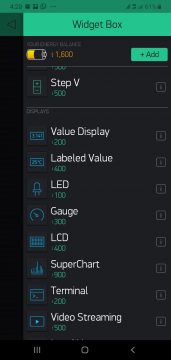
The Auth token will be sent to the email which will be used in coding. Now in the widget box select the gauge. Now we will give it name voltage and use it as virtual pin V0 and set the maximum value to 25.

Click on the PIN and select virtual pin V0.
Now insert labeled value and give it name as temperature and set the value between 18 to 100

Now insert another label and give it name humidity and assign it virtual pin 2

Now again in the wedge box we will insert a super chart and give it name as voltage and select the virtual pin V0 and give the minimum and maximum between 0 to 25.

Now click on the add data stream and we will make graph for both temperature and humidity. Our Blynk App for the Solar Panel Monitoring System is ready.
Blynk library for Arduino IDE:
To write code we will first installed the Blynk library. In order to install the Blynk library in the Arduino IDE click on the sketch and select the manage library.

Now in search, write Blynk and click on install

After the installation is finished, we will install temperature sensor library and now we will write DHT sensor in the search and click on the install.

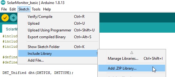
Now after installing the temperature sensor library we will install the simple timer library. Click on the sketch and then click on the insert zip file and select the zip file library. Download the Simple timer library:
After installing all the three libraries, now you can start writing your code.
Solar Panel Monitoring System ESP8266 Code:
|
1 2 3 4 5 6 7 8 9 10 11 12 13 14 15 16 17 18 19 20 21 22 23 24 25 26 27 28 29 30 31 32 33 34 35 36 37 38 39 40 41 42 43 44 45 46 47 48 49 50 51 52 53 54 55 56 57 58 59 60 61 62 63 64 65 66 67 68 69 70 71 72 73 74 75 76 77 78 79 80 81 82 83 84 85 86 87 88 89 90 91 92 93 94 95 96 97 98 99 100 101 102 103 104 105 106 107 108 109 110 111 112 113 114 115 116 117 118 119 120 121 122 123 124 125 126 127 128 129 130 131 132 133 134 135 136 137 138 139 140 141 142 143 144 145 146 147 148 149 150 151 152 153 154 155 156 157 158 159 160 161 162 163 164 165 166 167 168 169 170 171 172 |
<span style="font-family: 'times new roman', times, serif; font-size: 18pt;">#include #include #include #define DHTPIN 2 #define DHTTYPE DHT11 DHT_Unified dht(DHTPIN, DHTTYPE); // inverter on voltage and cutoff voltage float on_voltage = 12.0; float off_voltage = 11.5; // refresh interval uint32_t delayMS = 1000; int pinValue1; // inverter virtual pin int Voltage_sensor = A0; // voltage sensor int inverter = D2; // relay // voltage sensor float correctionfactor = 0; // adjust this for calibration float vout = 0.0; float vin = 0.0; // two resistors 30k and 7.5k ohms float R1 = 30000; // float R2 = 7500; // int value = 0; char data[80]; SimpleTimer timer; // Blynk token you received via email char auth[] = "YOUR_BLYNK_AUTH_TOKEN"; // Your WiFi credentials char ssid[] = "electronic_clinic"; char pass[] = "123456"; void setup() { Serial.begin(9600); pinMode(Voltage_sensor, INPUT); pinMode(inverter, OUTPUT); digitalWrite(inverter, HIGH); dht.begin(); Serial.println(F("Solar Power Monitor")); Blynk.begin(auth, ssid, pass); Blynk.virtualWrite(V5, 0); sensor_t sensor; dht.temperature().getSensor(&sensor); Serial.println(F("------------------------------------")); Serial.println(F("Temperature Sensor")); Serial.print (F("Sensor Type: ")); Serial.println(sensor.name); Serial.print (F("Driver Ver: ")); Serial.println(sensor.version); Serial.print (F("Unique ID: ")); Serial.println(sensor.sensor_id); Serial.print (F("Max Value: ")); Serial.print(sensor.max_value); Serial.println(F("°C")); Serial.print (F("Min Value: ")); Serial.print(sensor.min_value); Serial.println(F("°C")); Serial.print (F("Resolution: ")); Serial.print(sensor.resolution); Serial.println(F("°C")); Serial.println(F("------------------------------------")); // Print humidity sensor details. dht.humidity().getSensor(&sensor); Serial.println(F("Humidity Sensor")); Serial.print (F("Sensor Type: ")); Serial.println(sensor.name); Serial.print (F("Driver Ver: ")); Serial.println(sensor.version); Serial.print (F("Unique ID: ")); Serial.println(sensor.sensor_id); Serial.print (F("Max Value: ")); Serial.print(sensor.max_value); Serial.println(F("%")); Serial.print (F("Min Value: ")); Serial.print(sensor.min_value); Serial.println(F("%")); Serial.print (F("Resolution: ")); Serial.print(sensor.resolution); Serial.println(F("%")); Serial.println(F("------------------------------------")); // Set delay between sensor readings timer.setInterval(delayMS, timerEvent); timerEvent(); } void loop() { Blynk.run(); timer.run(); } void timerEvent() { // Get temperature event and print its value. sensors_event_t event; // Virtual pin 1 (V1) has temperature value dht.temperature().getEvent(&event); if (isnan(event.temperature)) { Serial.println(F("Error reading temperature!")); Blynk.virtualWrite(V1, "ERR"); } else { Serial.print(F("Temperature: ")); Serial.print(event.temperature); Serial.println(F("°C")); sprintf(data, "%.f", event.temperature); Blynk.virtualWrite(V1, data); // send data to blynk } // Get humidity event and print its value. // Virtual pin 2 (V2) has humidity value dht.humidity().getEvent(&event); if (isnan(event.relative_humidity)) { Serial.println(F("Error reading humidity!")); Blynk.virtualWrite(V2, "ERR"); } else { Serial.print(F("Humidity: ")); Serial.print(event.relative_humidity); Serial.println(F("%")); sprintf(data, "%.f", event.relative_humidity); Blynk.virtualWrite(V2, data); // send data to blynk } float vtot = 0.0; int loops = 10; // number of samples // loop multiple times and get average reading for (int i=0; i < loops; i++) { vtot = vtot + analogRead(Voltage_sensor); } value = vtot/loops; // voltage calculation vout = (value * 3.3) / 1024.0; // 3.3V vin = vout / (R2/(R1+R2)); vin = vin - correctionfactor; Serial.print("Voltage: "); Serial.print(vin, 4); Serial.println("V"); // Virtual pin 0 (V0) has voltage value sprintf(data, "%.1f", vin); Blynk.virtualWrite(V0, data); // send voltage value to blynk if (vin < off_voltage && digitalRead(inverter) == LOW) { digitalWrite(inverter, HIGH); Serial.println("TURNING RELAY OFF"); } if (vin > on_voltage && digitalRead(inverter) == HIGH) { digitalWrite(inverter, LOW); Serial.println("TURNING RELAY ON"); } if (digitalRead(inverter) == LOW) { Blynk.virtualWrite(V5, 255); Serial.println("Inverter is ON"); } else { Blynk.virtualWrite(V5, 0); Serial.println("Inverter is OFF"); } Serial.println("------------------"); Serial.println(""); } </span> |
Solar Panel Monitoring System Code Explanation:
You will need to add the following three libraries.
|
1 2 3 4 5 |
<span style="font-family: 'times new roman', times, serif; font-size: 18pt;">#include <DHT_U.h> #include <SimpleTimer.h> #include <BlynkSimpleEsp8266.h></span> |
Then we will write the command for the dht sensor that which type of sensor we are using in our case we are using DHT11 which is connected to the digital pin 2
|
1 2 3 4 5 |
<span style="font-family: 'times new roman', times, serif; font-size: 18pt;">#define DHTPIN 2 #define DHTTYPE DHT11 DHT_Unifieddht(DHTPIN, DHTTYPE);</span> |
Now we will set the voltage on which the inverter will be on and off. It can be set according to the requirements.
|
1 2 3 |
<span style="font-family: 'times new roman', times, serif; font-size: 18pt;">floaton_voltage = 12.0; floatoff_voltage = 11.5;</span> |
Then to update the frequency we will write the command
|
1 2 3 4 5 6 7 |
<span style="font-family: 'times new roman', times, serif; font-size: 18pt;">uint32_tdelayMS = 1000; int pinValue1; // inverter virtual pin This command is used to read the voltage of the sensor intVoltage_sensor = A0; // voltage sensor</span> |
This pin is connected with the relay module will turn on and off the inverter.
|
1 |
<span style="font-family: 'times new roman', times, serif; font-size: 18pt;">int inverter = D2; // relay</span> |
Now to calibrate the voltage value we write the command
|
1 2 3 4 5 6 7 |
<span style="font-family: 'times new roman', times, serif; font-size: 18pt;">// voltage sensor floatcorrectionfactor = 0; // adjust this for calibration floatvout = 0.0; float vin = 0.0;</span> |
Now to make the voltage divider for the voltage sensor we are using R1 and R2
|
1 2 3 4 5 |
<span style="font-family: 'times new roman', times, serif; font-size: 18pt;">float R1 = 30000; // float R2 = 7500; // int value = 0;</span> |
Now we will insert the authorization token which we will get from the email when we create the blynk application
|
1 2 3 4 5 6 7 8 9 10 11 |
<span style="font-family: 'times new roman', times, serif; font-size: 18pt;">// Blynk token you received via email charauth[] = "YOUR_BLYNK_AUTH_TOKEN"; Now insert the Wi-Fi name and password // Your WiFi credentials charssid[] = "electronic_clinic"; char pass[] = "123456";</span> |
Now in the setup function we will define that which pin will be used as input and which will be used as output.
|
1 2 3 4 5 6 7 |
<span style="font-family: 'times new roman', times, serif; font-size: 18pt;">Serial.begin(9600); pinMode(Voltage_sensor, INPUT); pinMode(inverter, OUTPUT); digitalWrite(inverter, HIGH);</span> |
Then we will write the commands to show the current temperature and voltage value on the serial monitor and on the Blynk application.
|
1 2 3 4 5 6 7 8 9 10 11 12 13 14 15 16 17 18 19 20 21 22 23 24 25 26 27 28 29 30 31 32 33 34 35 36 37 38 39 40 41 42 43 44 45 46 47 48 49 50 51 52 53 54 55 56 57 58 59 60 61 62 63 64 65 66 67 68 69 70 71 72 73 74 75 76 77 78 79 80 81 82 83 84 85 86 87 88 89 90 91 92 93 94 95 96 97 98 99 100 101 102 103 104 105 106 107 108 109 110 111 112 113 114 115 116 117 118 119 120 121 122 123 124 125 126 127 128 129 130 131 132 133 134 135 136 137 138 139 140 141 142 |
<span style="font-family: 'times new roman', times, serif; font-size: 18pt;">dht.begin(); Serial.println(F("Solar Power Monitor")); Blynk.begin(auth, ssid, pass); Blynk.virtualWrite(V5, 0); sensor_t sensor; dht.temperature().getSensor(&sensor); Serial.println(F("------------------------------------")); Serial.println(F("Temperature Sensor")); Serial.print (F("Sensor Type: ")); Serial.println(sensor.name); Serial.print (F("Driver Ver: ")); Serial.println(sensor.version); Serial.print (F("Unique ID: ")); Serial.println(sensor.sensor_id); Serial.print (F("Max Value: ")); Serial.print(sensor.max_value); Serial.println(F("°C")); Serial.print (F("Min Value: ")); Serial.print(sensor.min_value); Serial.println(F("°C")); Serial.print (F("Resolution: ")); Serial.print(sensor.resolution); Serial.println(F("°C")); Serial.println(F("------------------------------------")); // Print humidity sensor details. dht.humidity().getSensor(&sensor); Serial.println(F("Humidity Sensor")); Serial.print (F("Sensor Type: ")); Serial.println(sensor.name); Serial.print (F("Driver Ver: ")); Serial.println(sensor.version); Serial.print (F("Unique ID: ")); Serial.println(sensor.sensor_id); Serial.print (F("Max Value: ")); Serial.print(sensor.max_value); Serial.println(F("%")); Serial.print (F("Min Value: ")); Serial.print(sensor.min_value); Serial.println(F("%")); Serial.print (F("Resolution: ")); Serial.print(sensor.resolution); Serial.println(F("%")); Serial.println(F("------------------------------------")); // Set delay between sensor readings timer.setInterval(delayMS, timerEvent); timerEvent(); } void loop() { Blynk.run(); timer.run(); } voidtimerEvent() { // Get temperature event and print its value. sensors_event_t event; // Virtual pin 1 (V1) has temperature value dht.temperature().getEvent(&event); if (isnan(event.temperature)) { Serial.println(F("Error reading temperature!")); Blynk.virtualWrite(V1, "ERR"); } else { Serial.print(F("Temperature: ")); Serial.print(event.temperature); Serial.println(F("°C")); sprintf(data, "%.f", event.temperature); Blynk.virtualWrite(V1, data); // send data to blynk } // Get humidity event and print its value. // Virtual pin 2 (V2) has humidity value dht.humidity().getEvent(&event); if (isnan(event.relative_humidity)) { Serial.println(F("Error reading humidity!")); Blynk.virtualWrite(V2, "ERR"); } else { Serial.print(F("Humidity: ")); Serial.print(event.relative_humidity); Serial.println(F("%")); sprintf(data, "%.f", event.relative_humidity); Blynk.virtualWrite(V2, data); // send data to blynk }</span> |
Now we will read the pin value multiple times and get the average to reduce the noise.
|
1 2 3 4 5 6 7 8 9 10 11 12 13 14 15 16 |
<span style="font-family: 'times new roman', times, serif; font-size: 18pt;">floatvtot = 0.0; int loops = 10; // number of samples // loop multiple times and get average reading for (int i=0; i < loops; i++) { vtot = vtot + analogRead(Voltage_sensor); } value = vtot/loops;</span> |
Now calculate the voltage using the voltage divider equation
|
1 2 3 4 5 6 7 8 9 10 11 12 13 14 15 16 17 18 19 |
<span style="font-family: 'times new roman', times, serif; font-size: 18pt;">// voltage calculation vout = (value * 3.3) / 1024.0; // 3.3V vin = vout / (R2/(R1+R2)); vin = vin - correctionfactor; Serial.print("Voltage: "); Serial.print(vin, 4); Serial.println("V");</span> |
Now send the calculated data to the blynk application
|
1 2 3 4 5 |
<span style="font-family: 'times new roman', times, serif; font-size: 18pt;">// Virtual pin 0 (V0) has voltage value sprintf(data, "%.1f", vin); Blynk.virtualWrite(V0, data); // send voltage value to blynk</span> |
Now to check the voltage and the status of the inverter to turn on and off the inverter we will write the command.
|
1 2 3 4 5 6 7 8 9 10 11 12 13 14 15 16 17 18 19 20 21 22 23 24 25 26 27 28 29 30 31 32 33 34 35 36 37 38 39 40 41 42 43 44 45 46 47 48 49 50 |
<span style="font-family: 'times new roman', times, serif; font-size: 18pt;">if (vin <off_voltage&&digitalRead(inverter) == LOW) { digitalWrite(inverter, HIGH); Serial.println("TURNING RELAY OFF"); } if (vin >on_voltage&&digitalRead(inverter) == HIGH) { digitalWrite(inverter, LOW); Serial.println("TURNING RELAY ON"); } if (digitalRead(inverter) == LOW) { Blynk.virtualWrite(V5, 255); Serial.println("Inverter is ON"); } else { Blynk.virtualWrite(V5, 0); Serial.println("Inverter is OFF"); } Serial.println("------------------"); Serial.println(""); }</span> |
After uploading the code to the Nodemcu ESP8266 when you run the Blynk application, make sure you are connected to the WiFi and you have internet package, you will get the humidity, voltage, and temperature of the solar panel and also get the live graph.
Discover more from Electronic Clinic
Subscribe to get the latest posts sent to your email.