Esp8266 Iot battery monitor, battery voltage monitoring using nodemcu esp8266 wifi module
Last Updated on February 25, 2024 by Engr. Shahzada Fahad
Table of Contents
ESP8266 IoT Battery Monitor:
Esp8266 Iot battery monitor, battery voltage monitoring using nodemcu esp8266 wifi module- In this tutorial, you will learn how to monitor the Battery voltage from anywhere around the world and control DC light bulbs and other dc loads using 12v SPDT type relays. This is an IoT “internet of things” based project and is entirely based on the Nodemcu esp8266 wifi module and Blynk application. The battery voltage is displayed on the Gauge while the loads are controlled using the Numeric input buttons which I will explain in a minute. This tutorial covers
- Voltage sensor pinout and calculations
- Complete circuit diagram
- Blynk application designing and finally
- Testing
Amazon Links:
Other Tools and Components:
Super Starter kit for Beginners
PCB small portable drill machines
DISCLAIMER:
Please Note: these are affiliate links. I may make a commission if you buy the components through these links. I would appreciate your support in this way!
0-25v Voltage sensor:
This is the Voltage sensor Module that we will be using today, This Module is capable of measuring the voltages ranging from 0.02445v to 25volts dc. But if you want to measure voltages higher than 25volts then you can watch my tutorial on how to modify this voltage sensor for monitoring higher voltages, in this tutorial I performed all the calculations.
As you can see on one side we have a block terminal, this is where we connect the voltage and ground wires coming from The battery , solar panel or any other source. The Voltage wire is connected with the vcc terminal and the ground is connected with the gnd terminal.
On the other side we have three male headers labeled as +…. , s…. and -. ……
the s pin of the sensor module is connected with the analog pin of the Nodemcu esp8266 wifi module and the – pin is connected with ground of the nodemcu module. while the + pin is not connected.
Let’s have a look at the circuit diagram of the voltage sensor,

It simply consists of two resistors connected in series, Which makes a voltage divider circuit. As you can see the values of the resistors used in this module are 30k and 7.5k. Let’s perform calculations for this circuit.
The maximum input voltage of this module is 25 volts dc, but this applies when this voltage sensor is used with the Arduino, as the Arduino’s i/o pins are compatible with 5 volts. Let’s, first of all, calculate the output voltage of this sensor when the input voltage is 25 volts.
Vin = 25v
R1 = 30k ohm
r2 = 7.5k ohm
We can find out the Output voltage, by using the voltage divider
Vout = ( r2 x Vin ) / ( r1 + r2)
Vout = (7.5 x 1000 x 25) / (30k + 7.5k)
Vout = (7500 x 25) / 37500
Vout = 187500 / 37500
Vout = 5 Volt
so this sensor can be used with the Arduino without any problem. But it will damage the Nodemcu esp8266 module as the esp8266 is a 3.3v microcontroller, applying more than 3.6v on any pin can damage the chip.
So make sure the input voltage to this sensor never exceeds 18 volts. Always try to keep it below 18 volts. For 18 volts you will get 3.6 volts.
Enough with the voltage sensor, now let’s Discuss the complete circuit diagram.
IoT battery monitor Circuit Diagram:
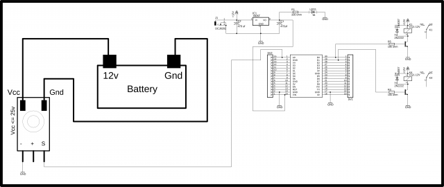
The 12v and ground wires of the battery are connected with the VCC and ground terminals of the voltage sensor. The minus pin of the voltage sensor is connected with the ground while the S pin of the voltage sensor is connected with the analog pin A0 of the Nodemcu module. The plus pin of the voltage sensor is not connected.
This is the 5v regulated power supply based on the LM7805 voltage regulator. J1 is the female power jack and this is where we connect the 12volts from a battery or 12v adopter or a Solar Panel. This power supply is used to power up the nodemcu esp8266 wifi module. two 470uf capacitors are connected at the input and output of the voltage regulator. 330-ohm resistor is connected in series with the 2.5 volts led. This is a current limiting resistor.
A wire from the output of the voltage regulator is connected with the Vin pin of the nodemcu esp8266 wifi module and the ground is connected with the ground.
A two-channel relay module is connected with the D0 and D1 pins of the nodemcu module. These relays can be used to control the ac or dc loads. These relays are of the type SPDT “single pole and double throw”. 2n2222 NPN transistors are used to control these relays. Now let’s make the cell phone application using Blynk.
Note: this old version of the Blynk app is no more functional. For the blynk mobile App setup and Blynk.cloud dashboard setup ready my article on the New Blynk V2.0. In this article I have explained how to migrate your projects from Blynk 1.0 to the new Blynk V2.0. You can also watch the video.
IoT battery monitor Blynk Application:
For the complete step-by-step designing watch the video tutorial given at the end of this article, or you can follow the steps given below.
First of all, open the Blynk application….
Click on the new project and enter the project name….
Click on the choose device and select Nodemcu…
make sure the connection type is set to wifi…
then click on the create button, an authentication token will be sent on your email id, simply copy and paste it in the programming…
Click anywhere on the screen and search for the gauge and add it…
Click on the gauge…
set the name as battery voltage…
Click on Pin and select virtual pin V2…
set the maximum value to 25…
change the font size then click on the push button and select 1 second…
Now again click on the screen and this time search for the numeric input and add it…
Click on the numeric input…
set the title as load1…
Click the pin and select virtual pin V10…
set the minimum and maximum values…
10 will be used to turn off the load1 while 11 will be used to turn on the load1…
for numeric input2 set the title as load2,
select the virtual pin V11 and set the minimum and maximum values as 12 and 13…
that’s it.
IoT battery monitor Programming:
|
1 2 3 4 5 6 7 8 9 10 11 12 13 14 15 16 17 18 19 20 21 22 23 24 25 26 27 28 29 30 31 32 33 34 35 36 37 38 39 40 41 42 43 44 45 46 47 48 49 50 51 52 53 54 55 56 57 58 59 60 61 62 63 64 65 66 67 68 69 70 71 72 73 74 75 76 77 78 79 80 81 82 83 84 85 86 87 88 89 90 91 92 93 94 95 96 97 98 99 100 101 102 103 104 105 106 107 108 109 110 111 112 113 114 115 116 117 118 119 120 121 122 123 124 125 126 127 128 |
#define BLYNK_PRINT Serial #include <ESP8266WiFi.h> #include <BlynkSimpleEsp8266.h> #include <SoftwareSerial.h> #include <SimpleTimer.h> int pinValue1; int pinValue2; int pinValue3; int pinValue4; int Vsensor = A0; // 0-25v voltage sensor is connected with the analog pin A0 of the arduino int load1 = D0; int load2 = D1; //For 0-25v voltage sensor float correctionfactor = 8; float vout = 0.0; float vin = 0.0; // two resistors 30K and 7.5k ohm float R1 = 30000; // float R2 = 7500; // int value = 0; char auth[] = "74ba97f2a0b34bb083bbab2a635b7aa1"; // Your WiFi credentials. // Set password to "" for open networks. char ssid[] = "ZONG MBB-E8231-6E63"; char pass[] = "electroniclinic1"; SimpleTimer timer; String myString; // complete message from arduino, which consistors of snesors data char rdata; // received charactors int firstVal, secondVal,thirdVal; // sensors // This function sends Arduino's up time every second to Virtual Pin (1). // In the app, Widget's reading frequency should be set to PUSH. This means // that you define how often to send data to Blynk App. void myTimerEvent() { // You can send any value at any time. // Please don't send more that 10 values per second. Blynk.virtualWrite(V1, millis() / 1000); } void setup() { // Debug console Serial.begin(9600); pinMode(Vsensor, INPUT); pinMode(load1, OUTPUT); pinMode(load2, OUTPUT); Blynk.begin(auth, ssid, pass); timer.setInterval(1000L,sensorvalue1); } void loop() { if (Serial.available() == 0 ) { Blynk.run(); timer.run(); // Initiates BlynkTimer } } void sensorvalue1() { int sdata = 0; // read the value at analog input value = analogRead(Vsensor); vout = (value * 5.0) / 1023.0; // see text vin = vout / (R2/(R1+R2)); vin = vin - correctionfactor; Serial.print("INPUT V= "); Serial.println(vin,4); sdata = vin; Blynk.virtualWrite(V2, sdata); } // in Blynk app writes values to the Virtual Pin 10 BLYNK_WRITE(V10) { pinValue1 = param.asInt(); // assigning incoming value from pin V10 to a variable if ( pinValue1 == 10 ) { digitalWrite(load1, LOW); } if ( pinValue1 == 11 ) { digitalWrite(load1, HIGH); } } // in Blynk app writes values to the Virtual Pin 11 BLYNK_WRITE(V11) { pinValue2 = param.asInt(); // assigning incoming value from pin V10 to a variable if ( pinValue2 == 12 ) { digitalWrite(load2, LOW); } if ( pinValue2 == 13 ) { digitalWrite(load2, HIGH); } } |
iot battery monitor Watch full Video Tutorial:
Discover more from Electronic Clinic
Subscribe to get the latest posts sent to your email.


Hi Shahzda, thank you for the interesting article you made available for us.
The Bill of Materials is VERY useful!
Can you clarify why you say that ” This is an iot “internet of things” based project”? Even the title says IOT voltage monitor…
Also you say that it can control dc loads; actually, any type of load can be controlled with the adequate implementation.
I am very new to this. Can you explain a little bit more how you finish with the Blink app settings and then you jump to 128 programming lines?. Is that for the Arduino? What is the use of the Arduino? Is it just to program the ESP8266? Is it possible to have a more “step by step” description for inexperienced beginners like me?
Thanks again for the fantastic work!
hello if you need help regarding this project send me mail on helpmeinproject@gmail.com
Hi When I opened up Blynk it is nothing like the demo that you are using. I am trying to build your voltage monitor but cannot get started with Blynk. Please can you advise. Thanks.
How would one go to use this with a 12 volt battery with a high of 13.8 volts and a low of 11.8. What would have to be changed in the code? Thank You
You can use it without any change as it will measure upto 25 volts on an Arduino or a maw voltage of 18 volts with an Node MCU