Temperature Logger for MLX 90614 using Arduino SD Card Module
Arduino Data Logger Excel using SD Card Module
Last Updated on September 21, 2024 by Engr. Shahzada Fahad
Table of Contents
Temperature Logger:
Temperature Logger for MLX 90614 using Arduino SD Card Module- In today’s article, you will learn how to make Temperature Logger using Arduino, MLX 90614 contactless Infrared Temperature Sensor, SD Card Module, and DS3231 RTC “Real-time Clock”. For the data logging, I will be using Microsoft Excel.
For the implementation of this project, it is not necessary for you to use the temperature sensor, you can use any other sensor. And if you guys don’t need the date and time, you can also drop the DS3231 Real Time Clock from your components list.
If you don’t have this SD card module, you can just use a micro-SD card adapter. I have already written a detailed article on this. I have also written an article on the DS3231 Real Time Clock. So, you must read my previous articles for learning the most basic things.
Now let me tell you what is my purpose of using real-time clock with a temperature sensor. You, people, know very well that due to global warming, the temperature of the earth has increased considerably, and this is not a good thing at all. I want to display the temperature as well as the date and time in the excel sheet, so that I can easily know what the temperature was on which date and time. This way I can compare my recorded data with next year’s temperature values.
I have also selected MLX 90614 on some basis because this temperature sensor is very fast as compared to other sensors. And another good thing about this temperature sensor is that, it’s a non-contact infrared temperature sensor.
So MLX 90614 is the best choice for this temperature logger project.
After sharing with you some useful information, now I am going to explain its working, and then I will start a practical demonstration. And afterwards, I will explain circuit diagram, Arduino programming, and how to open the recorded data in an excel sheet, and then how to display the temperature data using graphs.
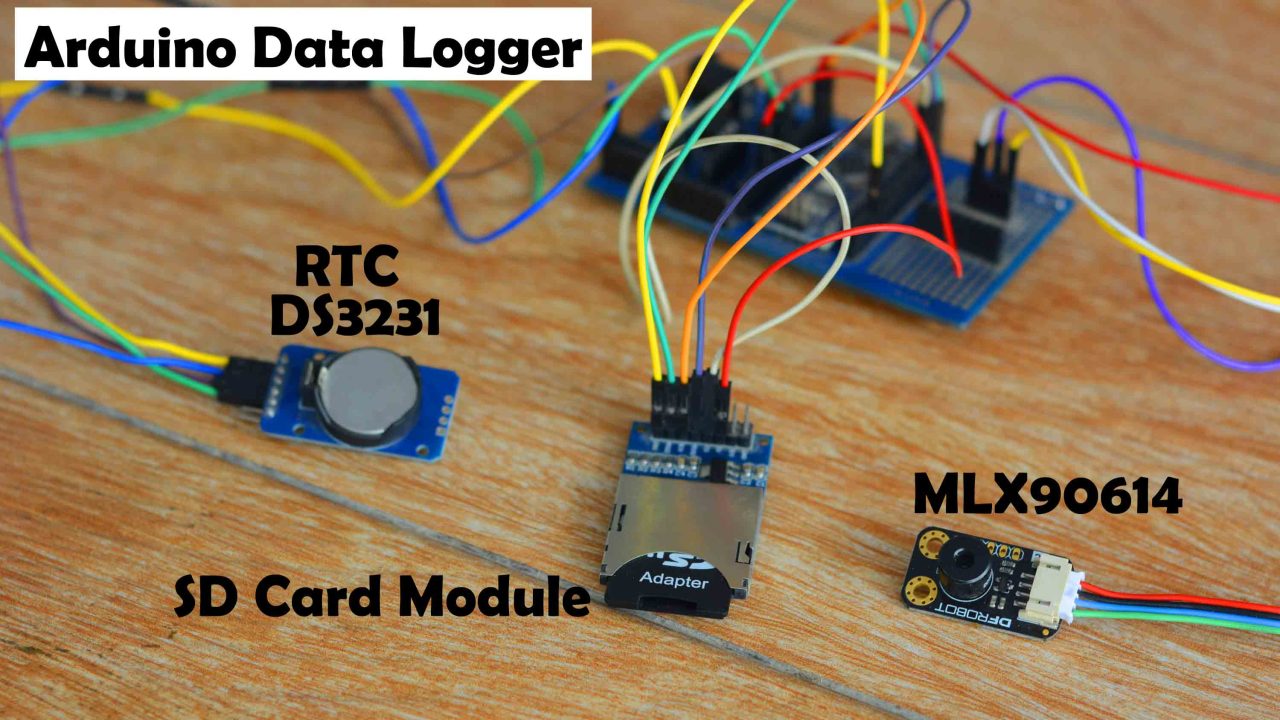
I have connected everything as per the circuit diagram which I will explain in a minute. Its working is very simple. Arduino measures the Temperature using the MLX 90614 Temperature sensor and takes the Date and Time information from the DS3231 Real Time Clock. Finally, Arduino stores this data in the micro SD card using CSV “Comma separated values” format. I will be storing the Date, Time, Day, and Temperature information in the file. For demonstration purposes, I will be logging data at 2 seconds intervals. But if you want you can increase or decrease this time interval in the programming. Now, let’s go ahead and start our practical demonstration.
First I inserted the micro SD card into the SD Card Adapter. Then I powered up the Arduino using my 12V adaptor. Finally, I started measuring the temperature. It was just a random testing.

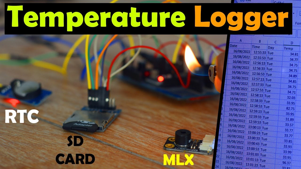
I measured the ambient temperature, table temperature, my hand’s temperature, and also measure the flame temperature. Just to make sure I get different temperature values. So, after logging enough data. I switched off the Arduino and removed the SD Card. I plugged it into my Laptop’s SD card Slot and opened the file.

The temperature spikes which you can see are due to; when I used the Flame. If you don’t know how to display this data on the Graphs then you can watch my video given at the end of this article. I am sure you may have fully understood the advantage of data logging and how beneficial it can be during the post analysis. Right now, I am displaying the temperature values versus the time. You can check the temperature at any particular time.
I am sure by now, you might have got an idea of how does this system work. So, without any further delay let’s get started!!!
Amazon Links:
Arduino Nano USB-C Type (Recommended)
MLX90614 Non-Contact Infrared Temperature Sensor
*Disclosure: These are affiliate links. As an Amazon Associate I earn from qualifying purchases.
SD Card Module:

This is the SD Card Reading and Writing Module which can be easily interfaced with Arduino and other embedded boards and microcontrollers. With a very basic program, you can read and write to the SD card over the SPI interface. This card module is provided with the onboard 3.3V voltage regulator due to which it can be interfaced with 3.3V compatible controller boards like ESP32 and ESP8266, etc. In order to use the micro SD card with this module, you will need a micro SD card adaptor.
SD Card Pinout:
This SD card module is provided with male headers which are clearly labeled as
- GND
- 3V
- 5V
- CS
- MOSI
- SCK
- MISO
- GND
If you are planning to use this Card Module with the Arduino then connect the 5v pin with the Arduino’s 5V, and if you are planning to use this Card module with the ESP32 then connect the 3.3v pin with the ESP32 3.3V pin. Never use 5 volts when using this SD card module with 3.3V compatible controller boards.
While performing the initial tests, I powered up the SD card module using 3.3V and it didn’t work. Then I powered up this module using the Arduino’s 5V and it worked. So, in a nutshell, if you are using the Card Module with the Arduino then use 5volts, and if you are using the Card Module with the ESP32 or ESP8266 then use 3.3V. For more details read my article available on www.electroniclinic.com. I will provide a link in the description. So, first, let’s start with the Arduino and Card Module.
SD Card Module, Description:
This SD Card Reader/Writer is ideal for many Micro-controller projects (Arduino, Pic, Versalino, etc…) including (but not limited to) projects involving sensor and other data logging activities. Audio playing and/or recording. Video, Image, and other multimedia storage and retrieval for advanced embedded applications. Processing large quantities of data with a robot, or storing/retrieving items larger than the limited memory available on your microprocessor. This can be used for a broad range of applications from scientific data collection for biological/geological and other statistical studies in the field, to storing map data for your robots surroundings in and outside the home.
Technical Specifications:
Working Voltage: 3.3 & 5V(DC Both required) Requires SPI Capable Microprocessor Size limitations are library dependent, but most microprocessors have libraries pre-coded that will support sizes upward of 1GB 7 wires required (including power and ground) Fits standard size SD Cards Package Contents: 1*SD Card Reader/Writer
DS3231 RTC Real Time Clock:
This is the RTC DS3231 module. The RTC stands for Real-Time Clock. You might be thinking why we need the RTC DS3231 module when the Arduino itself has the built-in timekeeper. Arduino is really powerful and we can make a real-time clock, but the problem comes in when the Arduino is turned off, or the power is disconnected, the time and date information is completely lost.

But if you look at the RTC DS3231 module it has a battery and can keep track of the Time and Date information even if the main power supply is disconnected or we reprogram the microcontroller.
RTC DS3231 Features:
The RTC DS3231is a low-cost, highly accurate Real Time Clock, which can maintain hours, minutes, and seconds. This module can also maintain the day, month, and year information. The RTC DS3231 module also has automatic compensation for leap years and for months with fewer than 31 days.
This Module can be powered up using 3.3 volts or 5 volts. As you can see clearly in the picture above, the DS3231 module has a total of 6 male headers and are clearly labeled. Out of these 6 Pins, we will be using only 4 Pins which are the SCL, SDA, VCC, and GND.
MLX90614 Temperature Sensor:
The DFRobot MLX90614 Infrared Temperature sensor which uses infrared rays to detect the temperature without direct contact with the object. This method gives us temperature very quickly and accurately. In recent years non-contact measurement methods have been used for medical, environmental monitoring, home automation, automotive electronic, aerospace and military applications. This sensor reads the surface temperature. We can use it to detect fever by reading the temperature of the body. The IR temperature probe consists of an optical system, photoelectric detector, and amplifier, signal processing and output module.
The optical system collects the infrared radiation in its field of view, whose area is decided by optical components and position of the thermometer and the infrared radiation energy is converted in to corresponding electrical signals when converging on the photoelectric detector. After being processed by the amplifier and signal processing circuit, calibrated according to the algorithm and target emissivity, the signal is converted in to temperature value of the target. We have used the Blynk application in which we will display the temperature. Using the Blynk application we can see the temperature everywhere in the world in the mobile. We will display the temperature in Fahrenheit and centigrade.

This sensor consists of four pins as shown in the figure.
- VCC
- GND
- SDA
- SCL
Specification
- SEN0206 (MLX90614-BBC)
- Operating Voltage: 3.3V – 5V
- Operating Current: 1.2mA
- Temperature: -70.01℃ to +382.19℃, (0.01 ℃ resolution)
- Interface Type: IIC
- Interface Line Sequence: VCC, GND, SCL, SDA
- FOV: 35°
- Dimensions: 31.5*18 mm/1.24 x 0.7 inches
SEN0263 (MLX90614-DCI)
- Operating Voltage: 3.3V-5V
- Operating Current: 1.2mA
- Temperature: -70.01℃ to +270℃,(0.01 ℃ resolution)
- Interface Type: IIC
- Interface Line Sequence: VCC,GND,SCL,SDA
- FOV: 5°
- Dimensions: 31.5*18mm/1.24 x 0.7 inches
Temperature Logger Circuit Diagram:

The 5V and GND pins of the SD Card Module are connected with the Arduino’s 5v and ground. CS is connected with pin 10, MOSI is connected with pin 11, SCK is connected with pin 13, and MISO is connected with pin 12 of the Arduino.
As the MLX90614 Temperature Sensor and DS3231 RTC Real Time Clock both are I2C supported modules so that’s why the SDA and SCL pins of both the modules are connected with the A4 and A5 pins on the Arduino. A4 is the SDA and A5 is the SCL. The Vin and GND pins of the MLX90614 are connected with the 3.3V and GND pins. While the Vin and GND pins of the DS3231 module are connected with the 5V and GND pins.
On the Left side is the regulated 5 volts power supply based on the linear voltage regulator 7805. Now, let’s take a look at the programming.
Required Arduino Libraries:
Before you start the programming, first of all, make sure you download the SD.h, RTClib.h, and DFRobot_MLX90614.h Libraries.
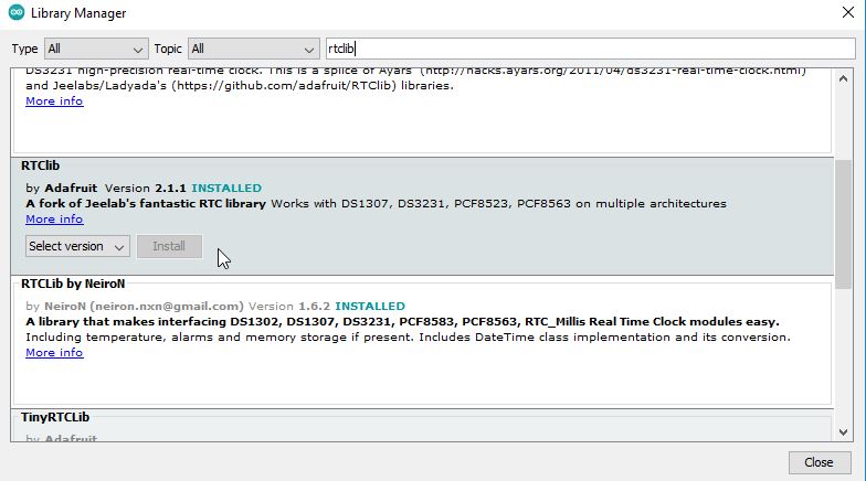
To install the SD.h library simply click on the Sketch Menu, then go to include library, and click on the Manage Libraries. Type sd in the search box and wait for a while.

As you can see I have already installed the latest version of the SD library.
Repeat the same steps for the RTClib library.
Now, repeat the same steps for the DFRobot_MLX9061 library.

After you have installed all the required libraries, then all you need is download the program given below. Anyway, all the instructions are well commented so you won’t have any problem in understanding the code.
Temperature Logger Arduino Programming:
|
1 2 3 4 5 6 7 8 9 10 11 12 13 14 15 16 17 18 19 20 21 22 23 24 25 26 27 28 29 30 31 32 33 34 35 36 37 38 39 40 41 42 43 44 45 46 47 48 49 50 51 52 53 54 55 56 57 58 59 60 61 62 63 64 65 66 67 68 69 70 71 72 73 74 75 76 77 78 79 80 81 82 83 84 85 86 87 88 89 90 91 92 93 94 95 96 97 98 99 100 101 102 103 104 105 106 107 108 109 110 111 112 113 114 115 116 117 118 119 120 121 122 123 124 125 126 127 128 129 130 131 132 133 134 135 136 137 138 139 140 141 142 143 144 145 146 147 148 149 150 151 152 153 154 155 156 157 158 159 160 161 162 163 164 165 166 |
/* SD card Temperature data logger SD card connections ** MOSI - pin 11 ** MISO - pin 12 ** CLK - pin 13 ** CS - pin 10 https://www.electroniclinic.com/ */ // Include the libraries we need #include <SPI.h> #include <SD.h> #include <Wire.h> #include "RTClib.h" #include <DFRobot_MLX90614.h> DFRobot_MLX90614_IIC sensor; // instantiate an object to drive our sensor RTC_DS3231 rtc; char daysOfTheWeek[7][4] = {"Sun", "Mon", "Tue", "Wed", "Thu", "Fri", "Sat"}; String Day; String Month; String Year; String Secs; String Minutes; String Hours; String dofweek; // day of week String myDate; String myTime; const int chipSelect = 10; // for SD card uint32_t LastTime=0; // Last Time we took a reading (from ,millis()) String CoreFileName="TLog_"; // This id the core name of the file to write to, String FileName=""; // The actual filename to write to based on the core name and a numeric addendum String DataString = ""; void setup() { bool FileFound=true; // See end of function uint16_t Index=0; // Open serial communications // We use this just for error reporting if problems are occuring Serial.begin(9600); // see if the card is present and can be initialized: if (!SD.begin(chipSelect)) { Serial.println("Card failed, or not present"); // don't do anything more: while (1); } if (! rtc.begin()) { Serial.println("Couldn't find RTC"); while (1); } if (rtc.lostPower()) { Serial.println("RTC lost power, lets set the time!"); // Comment out below lines once you set the date & time. // Following line sets the RTC to the date & time this sketch was compiled rtc.adjust(DateTime(F(__DATE__), F(__TIME__))); } while( NO_ERR != sensor.begin() ){ Serial.println("Communication with device failed, please check connection"); delay(3000); } Serial.println("Begin ok!"); /** * adjust sensor sleep mode * mode select to enter or exit sleep mode, it's enter sleep mode by default * true is to enter sleep mode * false is to exit sleep mode (automatically exit sleep mode after power down and restart) */ sensor.enterSleepMode(); delay(50); sensor.enterSleepMode(false); delay(200); while(FileFound) { FileName=CoreFileName+String(Index)+".csv"; //.csv = Comma Seperated Values FileFound=SD.exists(FileName); Index++; } // If we get this far filename is a valid none existing file TakeReading(); // Initial Reading } void loop() { TakeReading(); // You could do other stuff in the loop here if you wanted. Animate a display perhaps? } void TakeReading() { DateTime now = rtc.now(); Day = now.day(); Month = now.month(); Year = now.year(); Secs = now.second(); Hours = now.hour(); Minutes = now.minute(); dofweek = daysOfTheWeek[now.dayOfTheWeek()]; myDate = Day + "/" + Month + "/" + Year ; //myDate = myDate +dofweek+ " "+ Day + "/" + Month + "/" + Year ; myTime= Hours +":"+ Minutes +":" + Secs ; // send to serial monitor Serial.println(dofweek); Serial.println(myDate); //Serial.println(myTime); static uint16_t Time=0; /** * get ambient temperature, unit is Celsius * return value range: -40 C ~ 85 C */ float ambientTemp = sensor.getAmbientTempCelsius(); /** * get temperature of object 1, unit is Celsius * return value range: -40 C ~ 85 C */ float objectTemp = sensor.getObjectTempCelsius(); // print measured data in Celsius Serial.print("Ambient celsius : "); Serial.print(ambientTemp); Serial.println(" C"); Serial.print("Object celsius : "); Serial.print(objectTemp); Serial.println(" C"); DataString=DataString+myDate+","+myTime+","+dofweek+","+String(objectTemp); // open the file. note that only one file can be open at a time, // so you have to close this one before opening another. File dataFile = SD.open(FileName, FILE_WRITE); // if the file is available, write to it: if (dataFile) { // If this is the first reading then put column headings in first if(Time==0) dataFile.println("Date,Time,Day,Temp"); dataFile.println(DataString); dataFile.close(); } else // if the file isn't open, pop up an error: { Serial.print("error opening "); Serial.println(FileName); } DataString = ""; Time++; delay(2000); } |
You can see I am using a delay of 2 seconds. You can increase or decrease this time interval. I know using delays really disturbs the normal execution of the code. So, if you want you can use a timer to run the TakeReading() function. So, that’s all for now.
Watch Video Tutorial
Discover more from Electronic Clinic
Subscribe to get the latest posts sent to your email.


