Water Level Monitoring using ESP8266 and Arduino IoT Cloud
Table of Contents
Water level monitoring through Arduino IoT:
Water Level Monitoring using Nodemcu ESP8266 and Arduino IoT Cloud- Every beginner or intermediate level programmer wishes to make the water level monitoring system using Arduino or ESP8266, or ESP32, or any other controller board. I myself have made different versions of the water level monitoring system links to those articles are given below. Now day’s water wastage is very common issue in our society and also industries. Due to the advancement of technology human life has become easier and this project is also related to automation and control through which we will monitor the level of the water. The main concern of this project is to monitor the level of water through ultrasonic sensor. The sensor fetches the level information and send to NodeMCU ESP8266 which can be monitored through the Arduino IoT Cloud. As a beginner you can start with the standard HC-SR04 Distance Sensor and when you have learned the very basics then you can use the Waterproofed Ultrasonic Sensor. This project consists of:
- ESP8266 NodeMCU
- Ultrasonic Sensor
Previously I built the water level monitoring system using Nodemcu ESP8266 and Blynk application; I also built the water level monitoring system using ESP32 and ToF10120 Laser Distance sensor. If you are a beginner and you are just starting with the Water level monitoring project then I highly recommend you should read my article on water level monitoring using Arduino and LEDs.
Anyways, the Arduino IoT cloud is becoming very popular and it’s far more simpler than the other IoT platforms. You can read my getting started tutorial on the Arduino IoT Cloud which explains the extreme basics.
You can also ready my article on IoT based Water level monitoring and automatic water pump control system using the ESP32 WiFi + Bluetooth Module, Waterproof Ultrasonic Sensor, and the New Blynk V2.0 more…
Amazon Links:
Other Tools and Components:
Super Starter kit for Beginners
PCB small portable drill machines
*Please Note: These are affiliate links. I may make a commission if you buy the components through these links. I would appreciate your support in this way!
Ultrasonic sensor HC-SR04:
Ultrasonic Module HC-SR04 Distance Sensor can measure the distance to an object by using echo. It can measure the distance between the sensor and the object by the time from the sound wave of a specific frequency to the time when the sound wave is heard to bounce back.
HC-SR04 Ultrasonic Distance Sensor is perfect for all kind of projects that need distance measurements, e.g. avoiding obstacles. HC-SR04 provides 2cm-500cm non-contact measurement function, the ranging high accuracy can reach to 3mm.
Ultrasonic Sensor Module Working Principle:
Pull the Trig pin to high level for more than 10us impulse, the module start ranging.
The module automatically sends eight 40KHz square wave to detect whether a signal is returned.
Finished ranging, if you find an object in front, Echo pin will be high level, and based on the different distance, it will take the different duration of high level.
So we can calculated the distance easily.
The distance = ((Duration of high level)*(Sonic :340m/s))/2.
Distance L = 1/2 × T × C
Technical Parameters
- Use voltage: DC 5V
- Quiescent current: less than 2mA
- Level output: high 5V low 0V
- Induction angle: no more than 15 degrees(<15°)
- Detection range: 0.78~196 in/ (2cm~500cm)
- High accuracy: up to 0.12 in/(0.3 cm)
- Trigger Input Pulse width: 10uS
- Dimensions: 1.3 x 0.4 x 0.1 inch/3.03 x 1 x 0.25 cm (L*W*H)
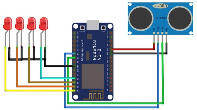
Circuit Diagram of water level monitoring through Arduino IoT:
As we know that the ultrasonic sensor consist of four pins which are:
- VCC
- Ground
- Trig
- Echo
The Echo pin will be used as input which will be connected with digital pin 6 and trigger pin will be connected with the digital pin 7 of the NodeMCU.
Four LEDs will be used to monitor the level of the water which will be connected with the digital pin 0, digital pin 1, digital pin 2 and digital pin 3. These LEDs will show the level high, ,medium and low.
After you have connected all the electronics as per the circuit diagram which you can see above. The next step is to design the application using the Arduino IoT Cloud. There are things which I have covered in the getting started tutorial and I highly recommend you should read that article otherwise you will face some issues while uploading the code. “Arduino IoT Cloud Getting Started Tutorial”.
Application design in Arduino IoT Cloud Platform:
This project is based on the Arduino IoT Cloud through which we will monitor the level of the water. In this project, we have used the gauge which will tells us the percentage of the water present in the tank whose values can be adjusted according to the size of the tank. Then we have added leds in the application which will shows us the status of the leds.
So in order to create the application we will open the Arduino IoT Cloud. First of all we will create the variables as we are using four leds so therefore we will create four variables which will be used for the leds in the application. So click on the add variable and create the variable with the name led1 and click on the add variable.
Similarly in the same way we will create three variables with the name led2, led3 and led4.
Then to control the gauge we will create the variable with the name water level which will shows us the percentage of the level of the water.
Then we will click on the add device and add the type of the device which we will be used during the creation of the device we will save the secret key which we will use in the network creation.
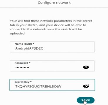
Then we will create the network by entering the SSID, password and secret key which we have copied during the creation of the secret key.
Dashboard design:
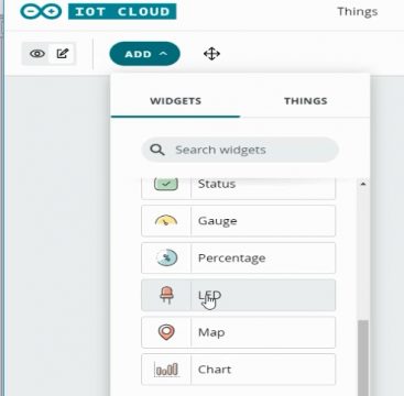
Then we will click on the dash board and add the widgets which we will be using in the project. So first of all we will add the led which will be used as a status and link it to the led1 variable.
In the similar way we will add another three leds and link to the variables.
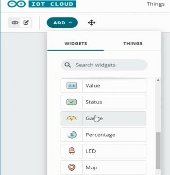
Then we will add gauge which will show us the percentage of water and link it to the water level variable.
So the application is created and now we will write the code. We will click on the sketch button to write code.
Water Level Monitoring Complete Code:
|
1 2 3 4 5 6 7 8 9 10 11 12 13 14 15 16 17 18 19 20 21 22 23 24 25 26 27 28 29 30 31 32 33 34 35 36 37 38 39 40 41 42 43 44 45 46 47 48 49 50 51 52 53 54 55 56 57 58 59 60 61 62 63 64 65 66 67 68 69 70 71 72 73 74 75 76 77 78 79 80 81 82 83 84 85 86 87 88 89 90 91 92 93 94 95 96 97 98 99 100 101 102 103 104 105 106 107 108 109 110 111 112 113 114 115 116 117 118 119 120 121 122 123 124 125 126 127 128 129 130 131 132 133 134 135 136 137 138 139 140 141 142 143 144 145 146 147 148 149 150 151 152 153 154 155 156 157 158 159 160 161 162 163 164 165 166 167 168 169 170 171 172 173 174 175 176 177 178 179 180 181 182 183 184 185 |
/* Sketch generated by the Arduino IoT Cloud Thing "Water level monitoring" https://create.arduino.cc/cloud/things/3fcb904d-9f3a-4cd5-8c60-0d4d5820ab65 Arduino IoT Cloud Variables description The following variables are automatically generated and updated when changes are made to the Thing CloudLight led3; CloudLight led2; CloudLight led1; CloudLight led4; int water_level; Variables which are marked as READ/WRITE in the Cloud Thing will also have functions which are called when their values are changed from the Dashboard. These functions are generated with the Thing and added at the end of this sketch. */ #include "thingProperties.h" #define trigpin D7 #define echopin D6 #define led_1 D0 #define led_2 D1 #define led_3 D2 #define led_4 D3 int duration, distance; void setup() { // Initialize serial and wait for port to open: Serial.begin(9600); // This delay gives the chance to wait for a Serial Monitor without blocking if none is found delay(1500); pinMode(trigpin, OUTPUT); pinMode(echopin, INPUT); pinMode(led_1, OUTPUT); pinMode(led_2, OUTPUT); pinMode(led_3, OUTPUT); pinMode(led_4, OUTPUT); digitalWrite(led_1, LOW); digitalWrite(led_2, LOW); digitalWrite(led_3, LOW); digitalWrite(led_4, LOW); // Defined in thingProperties.h initProperties(); // Connect to Arduino IoT Cloud ArduinoCloud.begin(ArduinoIoTPreferredConnection); /* The following function allows you to obtain more information related to the state of network and IoT Cloud connection and errors the higher number the more granular information you’ll get. The default is 0 (only errors). Maximum is 4 */ setDebugMessageLevel(2); ArduinoCloud.printDebugInfo(); } void loop() { ArduinoCloud.update(); // Your code here digitalWrite(trigpin, HIGH); delayMicroseconds(1000); digitalWrite(trigpin, LOW); duration = pulseIn(echopin,HIGH); distance = ( duration / 2) / 29.1; Serial.println("cm:"); Serial.println(distance); if( (distance > 0) && (distance <= 10) ) { digitalWrite(led_1, HIGH); digitalWrite(led_2, HIGH); digitalWrite(led_3, HIGH); digitalWrite(led_4, HIGH); led1=HIGH; led2=HIGH; led3=HIGH; led4=HIGH; Serial.println(distance); water_level=100-distance; } else if( (distance > 10) && (distance <= 20) ) { digitalWrite(led_1, LOW); digitalWrite(led_2, HIGH); digitalWrite(led_3, HIGH); digitalWrite(led_4, HIGH); led1=LOW; led2=HIGH; led3=HIGH; led4=HIGH; Serial.println(distance); water_level=100-distance; } else if( (distance > 20) && (distance <= 30) ) { digitalWrite(led_1, LOW); digitalWrite(led_2, LOW); digitalWrite(led_3, HIGH); digitalWrite(led_4, HIGH); led1=LOW; led2=LOW; led3=HIGH; led4=HIGH; Serial.println(distance); water_level=100-distance; } else if( (distance > 30) && (distance <= 40) ) { digitalWrite(led_1, LOW); digitalWrite(led_2, LOW); digitalWrite(led_3, LOW); digitalWrite(led_4, HIGH); led1=LOW; led2=LOW; led3=LOW; led4=HIGH; Serial.println(distance); water_level=100-distance; } else if( (distance > 50) ) { digitalWrite(led_1, LOW); digitalWrite(led_2, LOW); digitalWrite(led_3, LOW); digitalWrite(led_4, LOW); led1=LOW; led2=LOW; led3=LOW; led4=LOW; water_level=100-distance; } } void onLed3Change() { // Do something } void onLed2Change() { // Do something } void onLed1Change() { // Do something } void onLed4Change() { // Do something } void onWaterLevelChange() { // Do something } |
Then we will select the board and port and upload the code to the NodeMCU ESP8266 and we will monitor the water level on the Arduino IoT Cloud using our computer or you can also find the same application on your cell phone which is automatically generated. I have to remind you once again, read my article “Getting started with the Arduino IoT Cloud”, or you can also watch the video given below.


its not working.I followed all the steps .HELP