Xiao ESP32C3 & Xiao ESP32C6 Ultimate Development Board – One PCB for WiFi 6, Relays & IoT Power
Last Updated on February 28, 2026 by Engr. Shahzada Fahad
Table of Contents
Description:
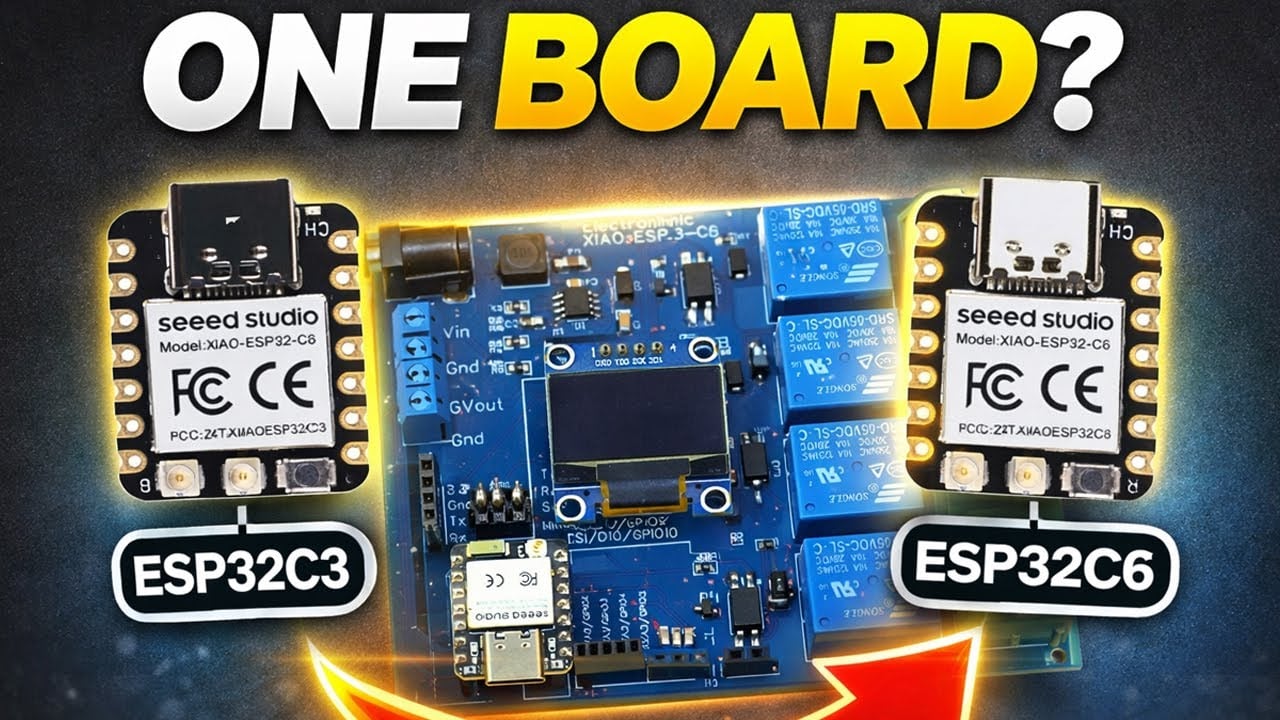
Xiao ESP32C3 & Xiao ESP32C6 Ultimate Development Board – One PCB for WiFi 6, Relays & IoT Power– Imagine having one development board that works perfectly with two powerful microcontrollers; the Xiao ESP32-C3 and the Xiao ESP32-C6.
Same size, same pinout, but completely different capabilities; and today, we are building a board that supports both. No more swapping hardware; just one universal Xiao dev board designed exactly the way makers and IoT developers want it.
In this article, I will show you how I designed a compact, feature-packed development board that gives the Xiao ESP32C3 and Xiao ESP32C6 the power, ports, protection, and expandability they truly deserve. Whether you are building IoT dashboards, automation systems, or experimenting with Wi-Fi 6 on the Xiao ESP32-C6; this custom board is going to make your life a whole lot easier.
So, let’s jump in and build the ultimate Xiao ESP32C3/C6 development board; from concept… to circuit… to fully working hardware.
I have already written detailed getting started articles on both the Xiao ESP32C3 and the Xiao ESP32C6. Make sure to check these out first; they will help you a lot.
Amazon Links:
Other Tools and Components:
ESP32 WiFi + Bluetooth Module (Recommended)
Arduino Nano USB C type (Recommended)
*Please Note: These are affiliate links. I may make a commission if you buy the components through these links. I would appreciate your support in this way!
Xiao ESP32C3/C6 Dev board Schematic:
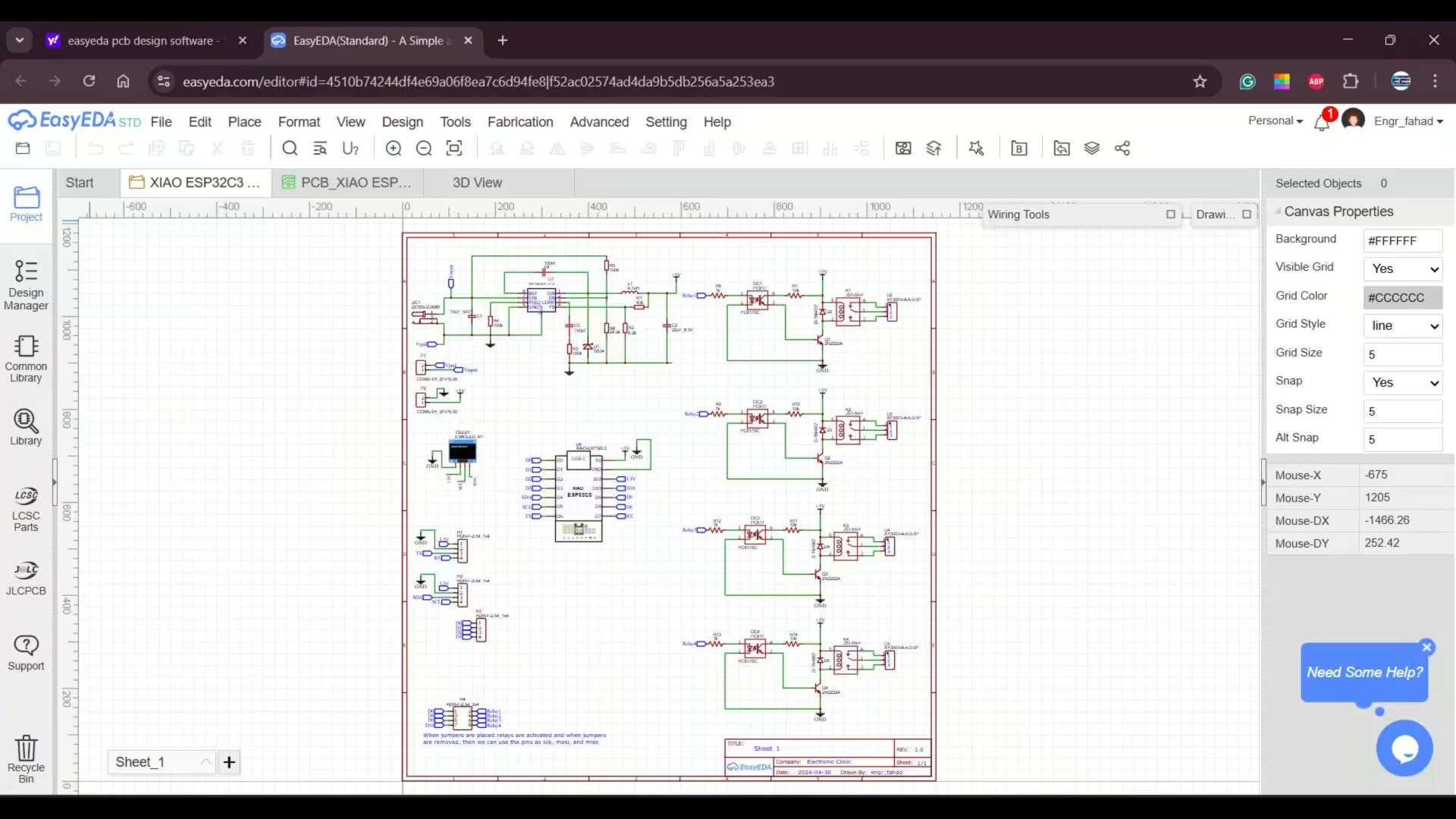
I started off by designing the schematic in EasyEDA, which is completely free and honestly much easier to use compared to most PCB design software. And since I wanted this development board to be powerful enough to handle high-torque servo motors, GSM/GPS modules, relays, and even heavy modules like 3G, 4G, and 5G, I included a 5V 3A power supply.
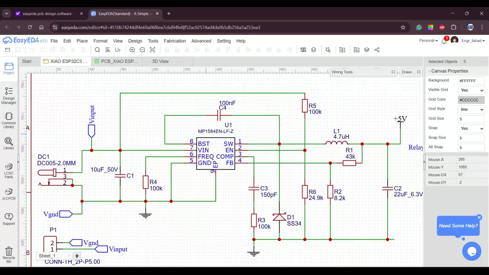
I have already used this exact power supply in my previous development boards, and I even made a full dedicated video about it; you can also read the article my 5V 3A power supply. so if you want a deeper explanation, you can read that article as well.
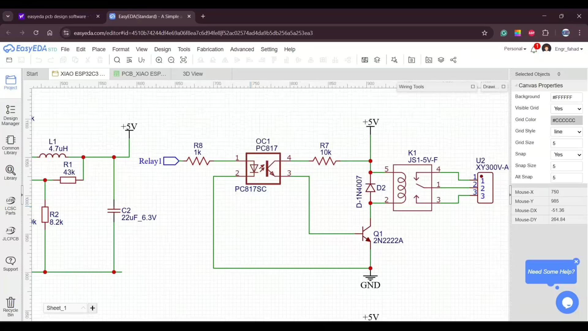
Along with that, I added four SPDT 5V relays. And to keep these relays completely isolated from the microcontroller side, I am using PC817 optocouplers. These are extremely important in a professional design because they electrically separate the high-voltage or high-current relay section from the sensitive controller circuitry. So even if there’s noise, voltage spikes, or a fault condition on the load side, the optocoupler protects the microcontroller by preventing that interference from flowing back.
I have also placed diodes across each relay coil. These are flyback or freewheeling diodes, and they are crucial because when the relay coil switches off, it generates a high-voltage spike. Without these diodes, that spike can damage the transistor or even the controller. The diode simply absorbs that energy and keeps the entire circuit safe.
To drive each relay, I am using a 2N2222 NPN transistor. I have already made a dedicated video on relay driver circuit calculations and design, and you can also read my article on different types of relays and how to use them. This article explains; how control different types of relays.
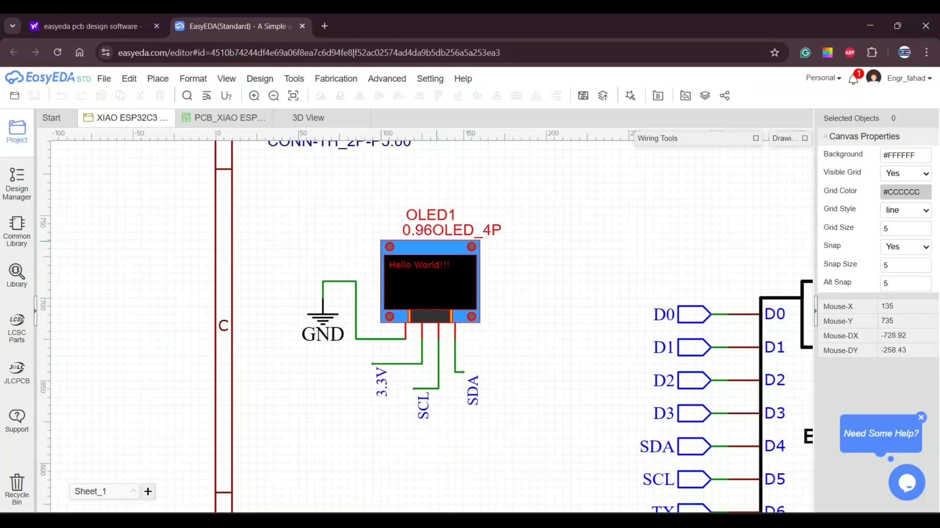
For this development board, I also added an SSD1306 OLED display module; and of course, all those additional terminal blocks. I will explain their purpose after we finish building the development board.
About PCB Designing:
After completing the schematic, the next most important step is deciding the size and overall design of the PCB.
Since my goal was to create a development board specifically for experiments, I kept the design simple and intentionally made the board larger. This gives users plenty of space to work comfortably and connect different modules without feeling restricted.
Once the PCB layout was ready, I generated the Gerber files along with the BOM and Pick and place files. And if you are not familiar with this process, you can always check out my PCB designing videos and articles; I have explained everything in detail there.
You can download the original schematic, PCB design files, BOM, and all the other resources from my Patreon page.
So, I sent those Gerber files to Seeed Studio, and I also ordered a stencil. And then, a few days later…
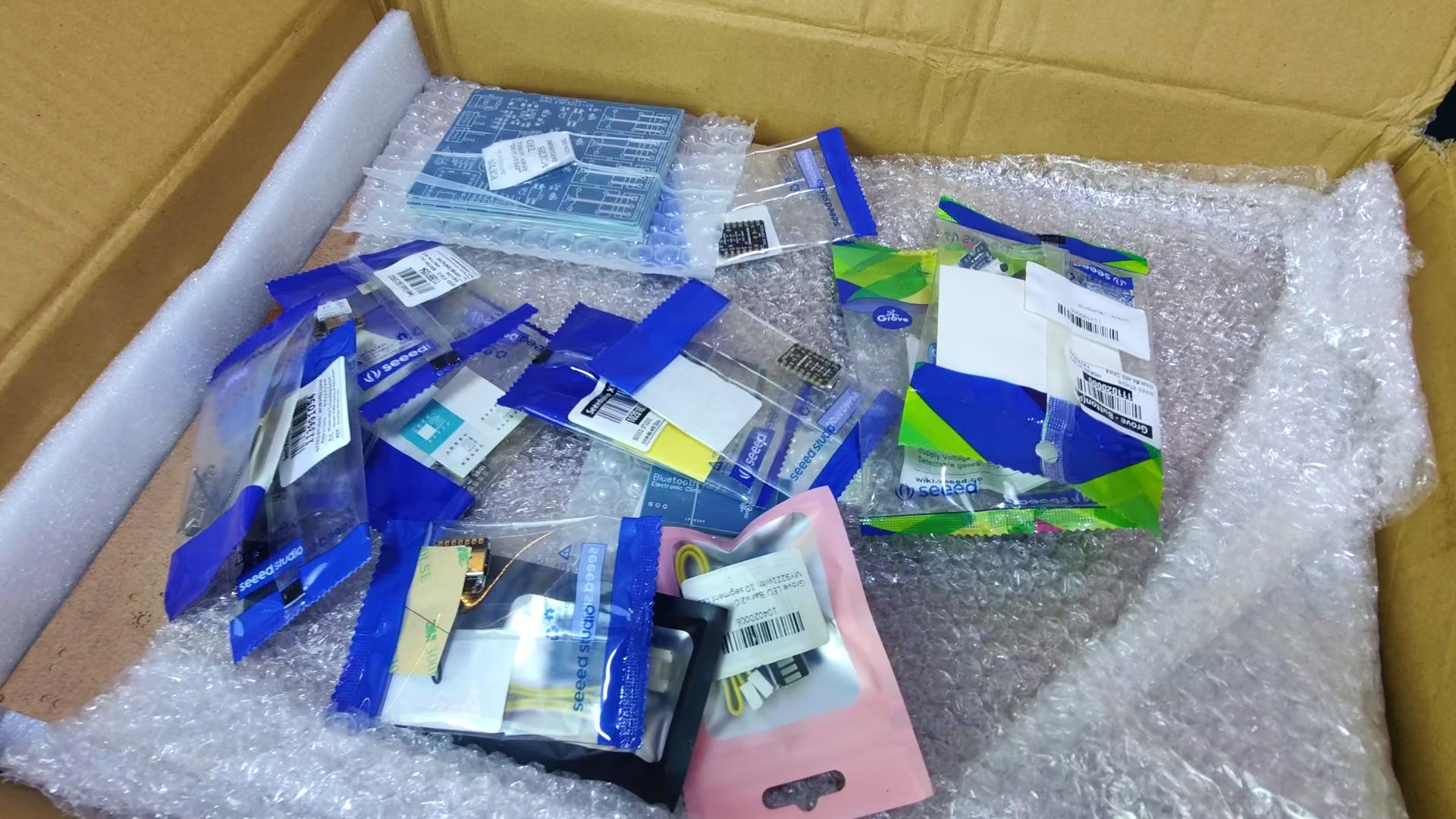
I received this huge package from Seeed Studio. They didn’t just send the PCBs and the stencil; they also included multiple sensors, along with several Xiao ESP32C3 and ESP32C6 boards. I genuinely wasn’t expecting that.
I thought they would only send the PCBs, but they sent way more than that. And now, I can build multiple development boards and use all these sensors to run tests and perform different experiments.
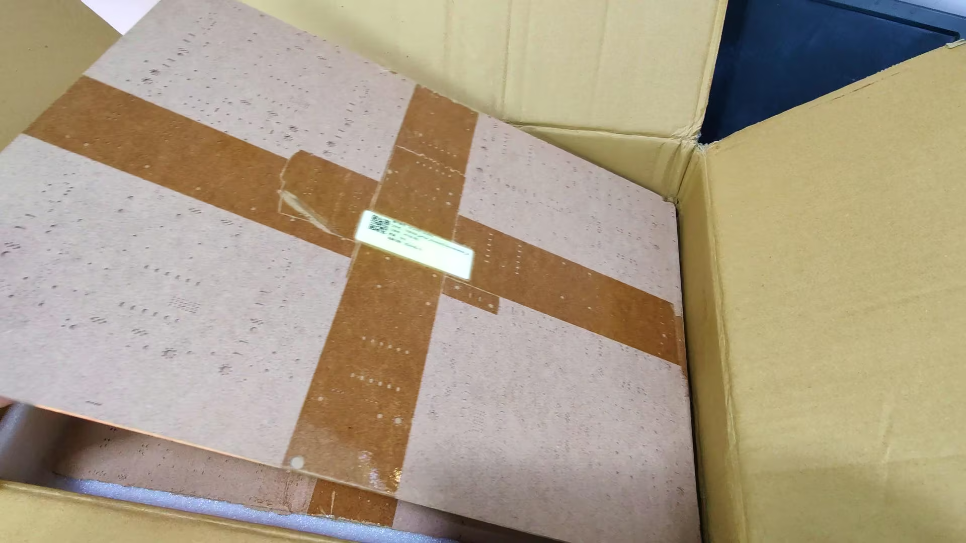
These are the stencils, nicely sandwiched between two hardboards to prevent any bending during shipping. And just look at the quality and size of this stencil; it’s absolutely amazing.
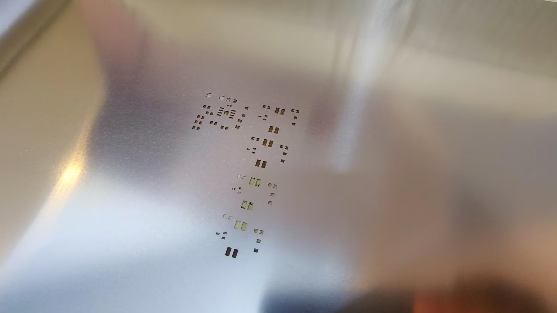
The cuts are super clean, and the overall finish is exactly what you need for precise SMD soldering.
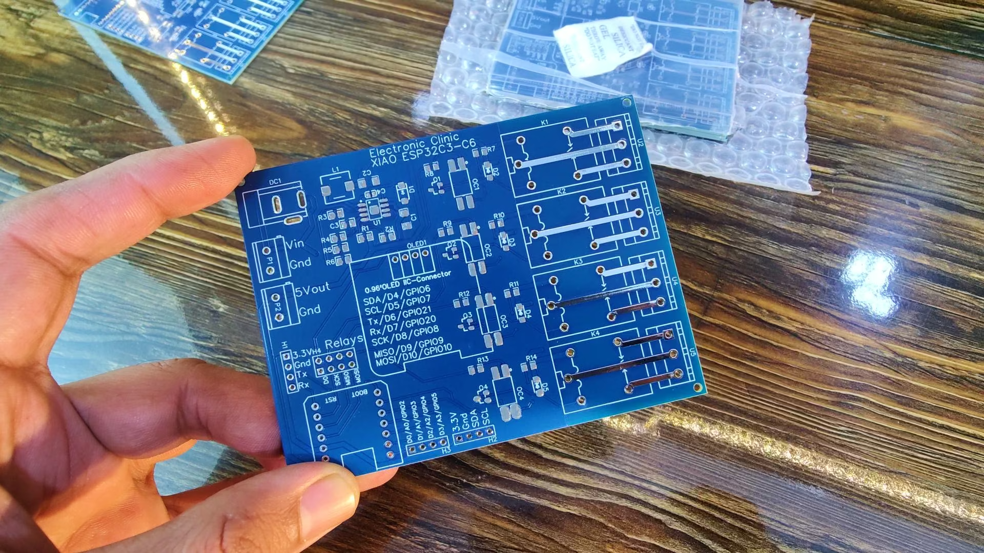
And here are the PCBs; the quality is absolutely top-notch.
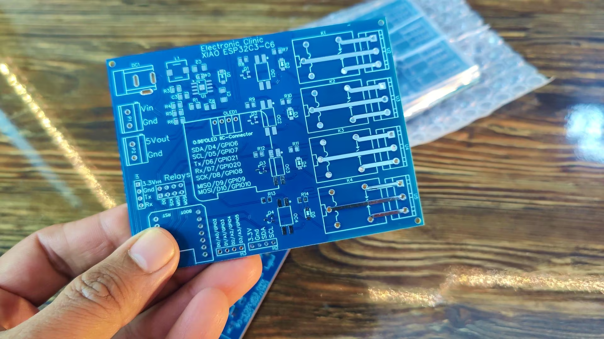
I don’t think I even need to say much; the finish speaks for itself. Seeed Studio always puts quality at the top of their priority list, and I am saying this from experience because I have used a lot of their products over the years. They never disappoint.
Anyway, now I am going to use the stencil to apply solder paste onto the PCB. I have already made a very detailed video on SMD soldering and you can also read my article on SMD soldering; how to use a stencil, how to place SMD components on the PCB, what temperature to use for soldering; everything is explained step by step. You will find the link in the description below.
So, as you can see, I have applied the solder paste on the PCB, and next I am going to place all the components on it.
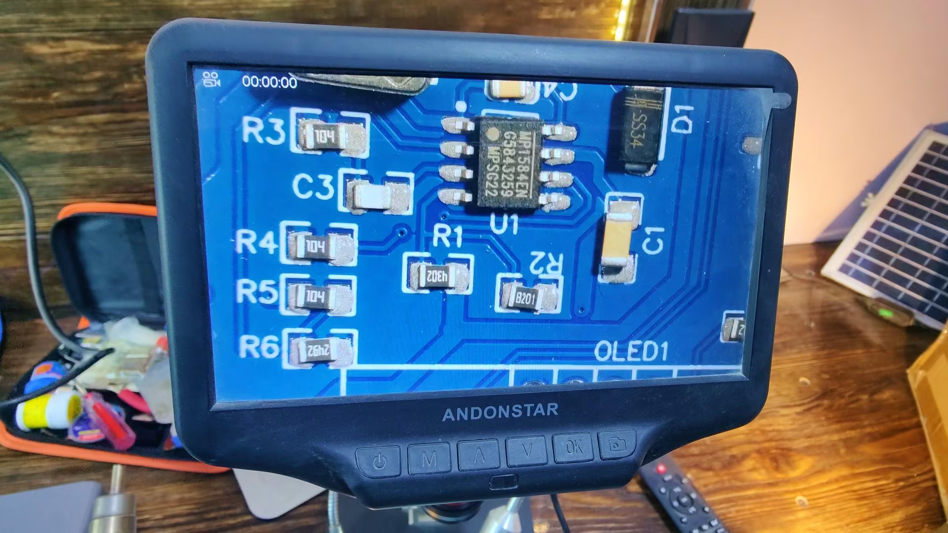
And as you can see, I have placed all the components on the PCB. The ANDONSTAR digital microscope made the whole process of placing the SMD components super easy and precise.
And then I started the soldering.
About the Development Board:
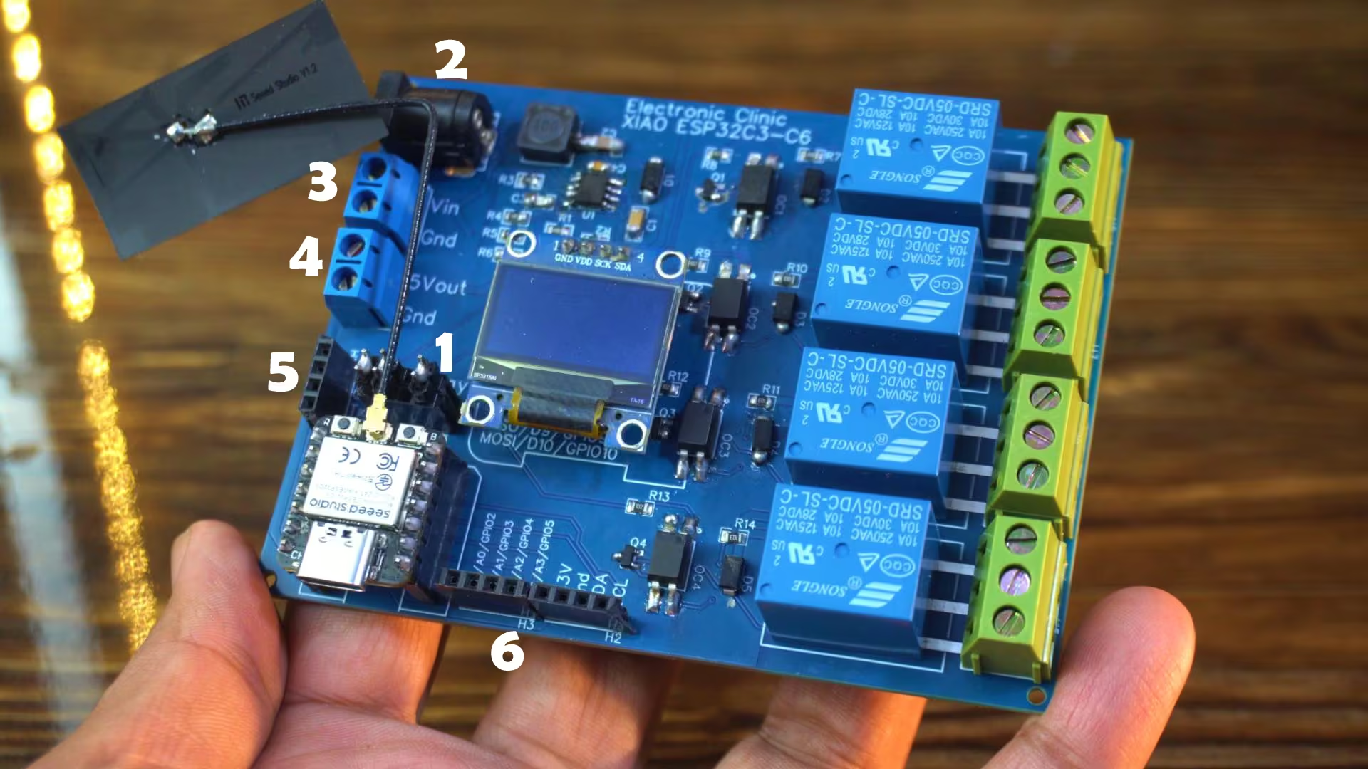
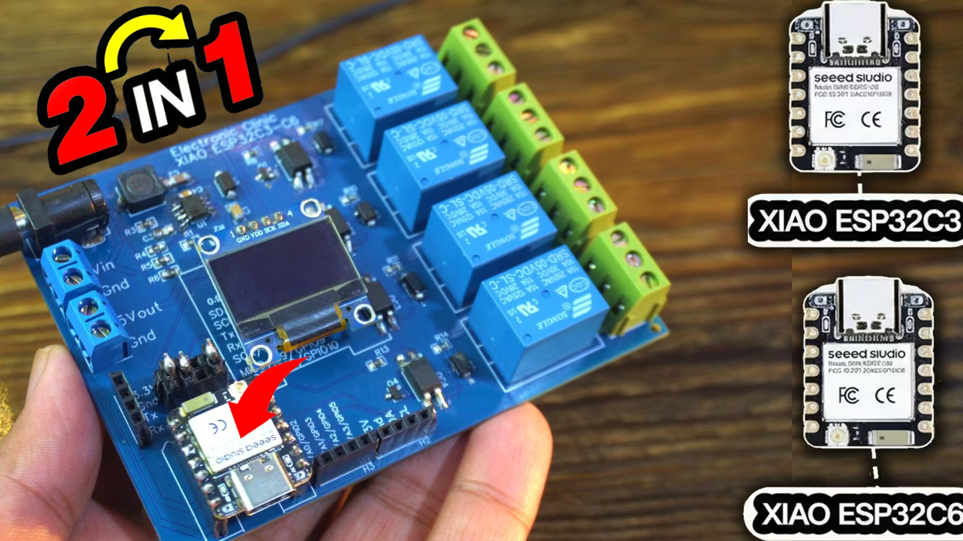
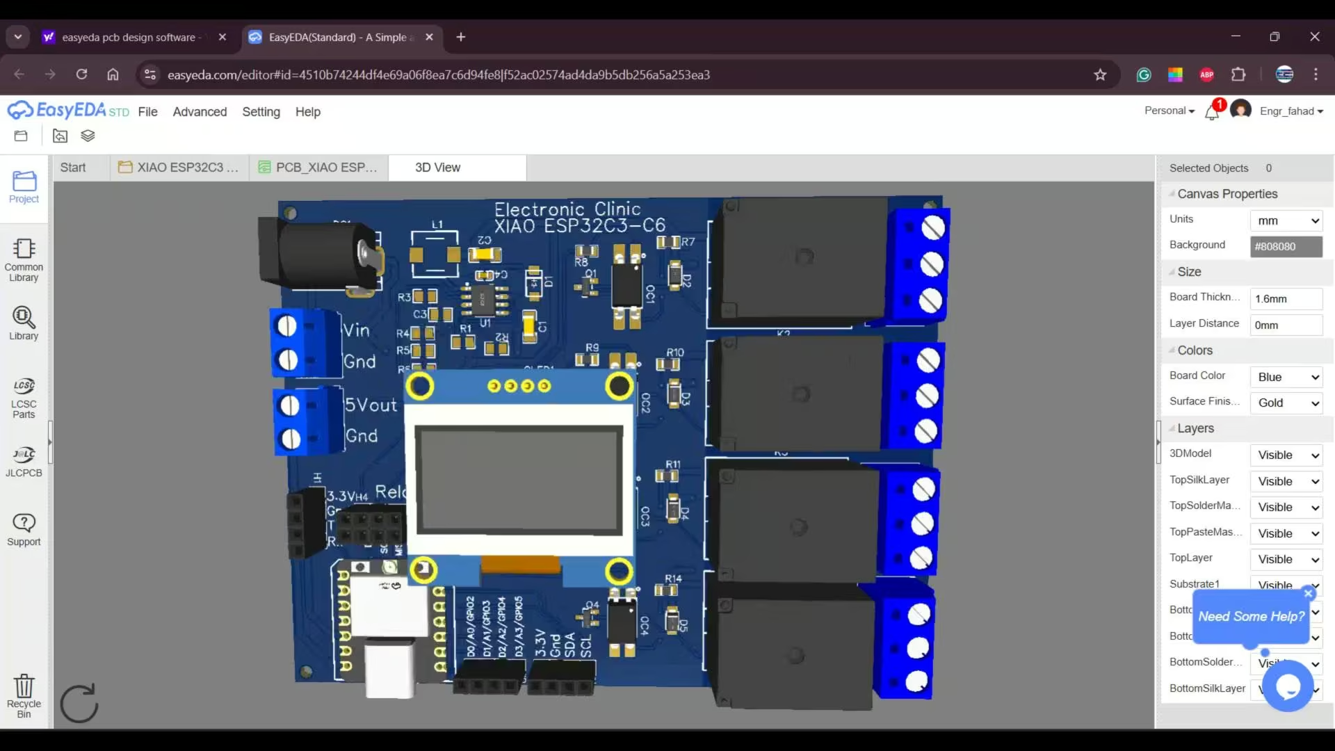
As you can see, our development board is fully assembled and ready. For now, I have installed the Xiao ESP32C3, and after testing this, we will also try the Xiao ESP32C6 since the board supports both.
1) Anyway, you can see that I have added these jumpers here. These pins serve two purposes: they are used for SPI communication as well as for controlling the relays. When the jumpers are connected, the pins are assigned to the relays. And when we want to use those same pins for SPI communication, we simply remove the jumpers. It’s a simple and flexible setup.
2) We can power this board using a DC adapter; anything from 9 volts to 25 volts will work perfectly fine.
3) And you can even power it through a solar panel. Just connect the positive and negative wires from your solar panel to the VIN and GND pins on the terminal block.
4) If you need 5V for any sensor or breakout board, you can take it from this terminal block right here. It’s labeled as 5V OUT and GND.
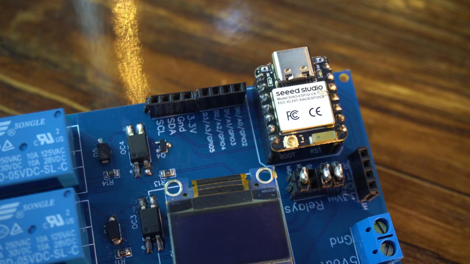
5) With these female headers, you can connect any modules that support serial communication. They are labeled clearly as 3.3V, GND, TX, and RX. And just like that,
6) I have added a few more female headers for additional I/O pins, all clearly labeled. Most of the details I have already explained earlier while going through the schematic.
So, let’s go ahead and test the board. First, we will start by checking the OLED display.
XIAO ESP32C3 and SSD1306 Oled Display:
Here’s a simple piece of code I have written to test the SSD1306 OLED display module. It will print the text “Electronic Clinic” on the screen. So, let’s go ahead and upload this program to see it in action.
Xiao ESP32C3 & Oled Code:
|
1 2 3 4 5 6 7 8 9 10 11 12 13 14 15 16 17 18 19 20 21 22 23 24 25 26 27 28 29 30 31 32 33 34 |
#include <Wire.h> #include <Adafruit_GFX.h> #include <Adafruit_SSD1306.h> // ================= OLED SETTINGS ================= #define SCREEN_WIDTH 128 #define SCREEN_HEIGHT 64 Adafruit_SSD1306 display(SCREEN_WIDTH, SCREEN_HEIGHT, &Wire, -1); void setup() { Serial.begin(115200); // Initialize OLED Wire.begin(); // SDA=D4, SCL=D5 on Xiao ESP32-C3 if(!display.begin(SSD1306_SWITCHCAPVCC, 0x3C)) { Serial.println("OLED not found"); for(;;); // Stop here if display failed } display.clearDisplay(); display.setTextColor(WHITE); display.setTextSize(2); display.setCursor(0, 20); display.println("Electronic"); display.setCursor(0, 40); display.println("Clinic"); display.display(); } void loop() { // Nothing here; display stays static } |
Practical Demo:
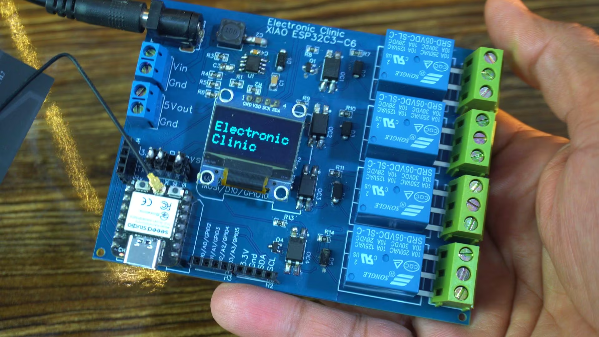
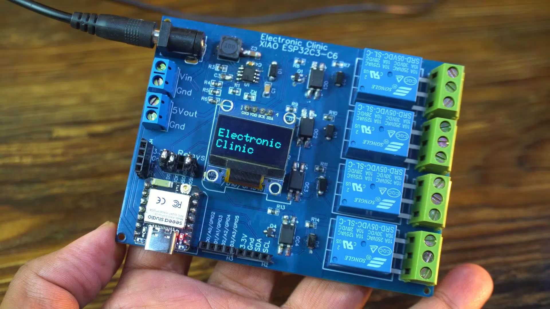
It’s working perfectly. Just look at that; I have printed “Electronic Clinic” on the screen. It’s always a satisfying moment when the first text shows up on a brand-new board. It tells you everything is wired correctly, the power is stable, and the controller is talking to the display exactly the way it should. A small thing… but a big confidence boost before moving on to the rest of the testing.
XIAO ESP32C3 and 5V Relays:
I am going to use this code to test the relays.
Code:
|
1 2 3 4 5 6 7 8 9 10 11 12 13 14 15 16 17 18 19 20 21 22 23 24 25 26 27 28 29 30 31 32 33 34 35 36 37 38 39 40 41 42 43 44 45 46 47 48 49 50 51 52 53 54 55 |
// define led according to pin diagram int relay1 = D0; int relay2 = D8; int relay3 = D9; /* I won’t be using D9 to control a relay in the future. When a relay is connected to D9 and I power up the controller, the relay doesn’t work. But if I disconnect the relay from D9, power up the controller first, and then reconnect the relay, it works normally. This happens because D9 is involved in the ESP32-C3’s boot process and is not a stable, general-purpose output during power-up. Any external load—like a relay driver or transistor—interferes with the pin’s boot behavior, preventing it from working correctly until the system has fully initialized. To avoid this issue, it’s better to use a different GPIO that is safe during boot. */ int relay4 = D10; void setup() { // initialize digital pin led as an output Serial.begin(115200); pinMode(relay1, OUTPUT); pinMode(relay2, OUTPUT); pinMode(relay4, OUTPUT); } void loop() { digitalWrite(relay1, HIGH); // turn the LED on Serial.println("Relay1 ON"); delay(1000); // wait for a second digitalWrite(relay2, HIGH); // turn the LED on Serial.println("Relay2 ON"); delay(1000); digitalWrite(relay4, HIGH); // turn the LED on Serial.println("Relay4 ON"); delay(1000); digitalWrite(relay1, LOW); // turn the LED off Serial.println("Relay1 OFF"); delay(1000); // wait for a second digitalWrite(relay2, LOW); // turn the LED off Serial.println("Relay2 OFF"); delay(1000); // wait for a second digitalWrite(relay4, LOW); // turn the LED off Serial.println("Relay4 OFF"); delay(1000); // wait for a second } |
I have already uploaded the program, so now let’s see it in action and watch how these relays respond.
Practical Demo:
In the image you can’t see it. So, I recommend watching the video, given at the end of this article.
It’s working! I am sure you can hear that satisfying clicking sound of the relays. Now I can use these relays to control AC loads around my room. In upcoming videos, I will be using this development board for some really amazing projects. So, make sure to subscribe if you don’t want to miss any of those!
Xiao ESP32C6:
Now let’s test the OLED display and the relays using the Xiao ESP32C6.
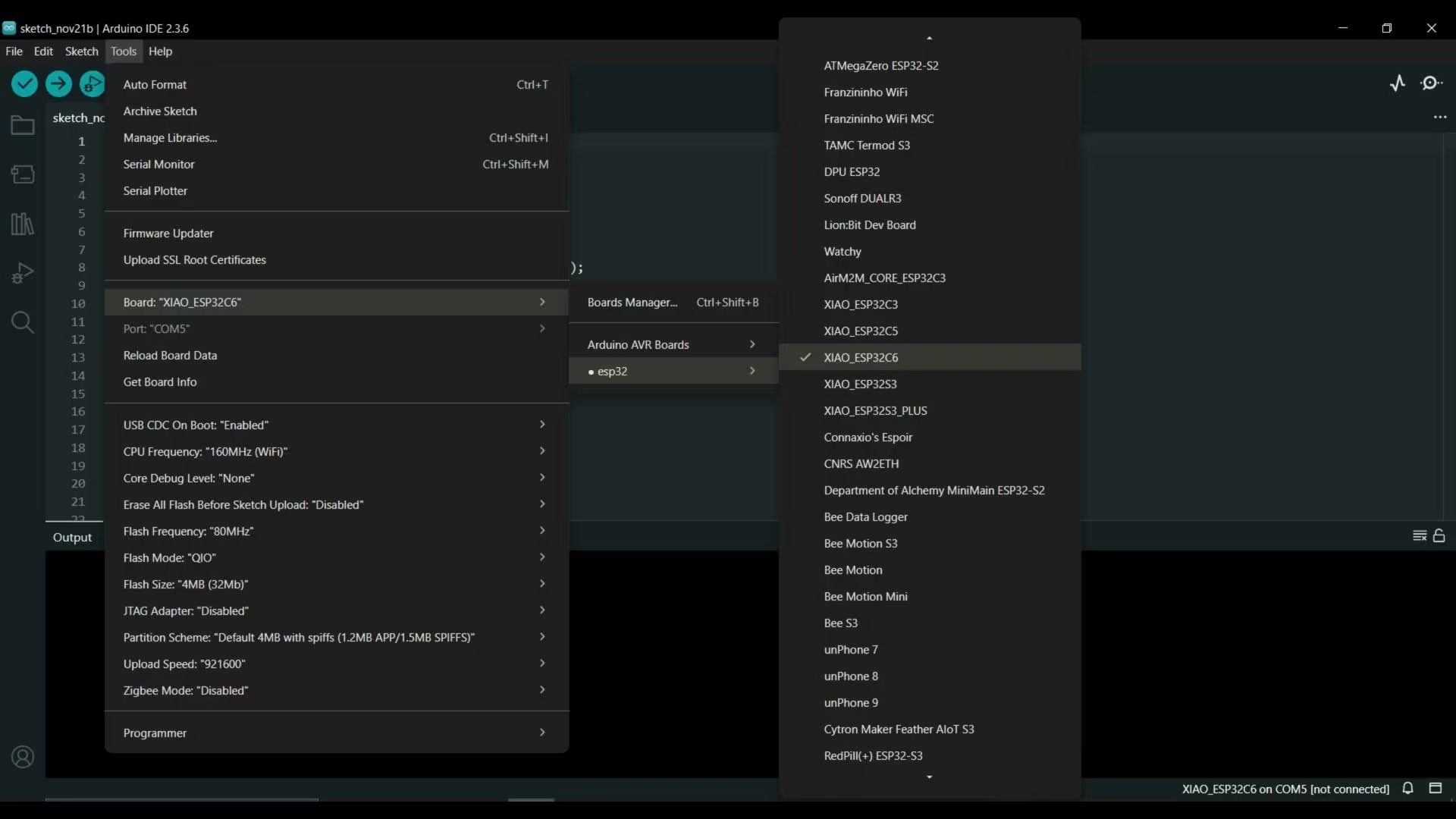
Just a quick note; for the Xiao ESP32C6, make sure you have the latest version of the Arduino IDE installed, and also update the ESP32 boards package. Otherwise, the Xiao ESP32C6 won’t show up in the boards list.
As I mentioned earlier, the Xiao ESP32C3 and Xiao ESP32C6 share the same size and pin layout. This means you can run the exact same code on the ESP32C6 without changing a single line.
The only thing you need to do is select Xiao ESP32C6 while uploading the code — and that’s it.
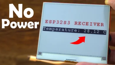
The “Electronic Clinic” text is now displayed perfectly on the OLED.
I also uploaded the relay testing code, and as you can hear, the relays are clicking just like before.
If you want, you can download the original schematic, PCB design files, and all the other resources from my Patreon page.
So, that’s all for now.
Frequently Asked Questions
What is special about the Xiao ESP32C3 & Xiao ESP32C6 development board?
This development board supports both the Xiao ESP32C3 and Xiao ESP32C6 on a single PCB. It includes a 5V 3A power supply, four isolated SPDT relays, an SSD1306 OLED display interface, flexible jumpers for SPI or relay control, and multiple labeled terminal blocks for easy expansion.
Can the same code run on Xiao ESP32C3 and Xiao ESP32C6?
Yes. The Xiao ESP32C3 and Xiao ESP32C6 share the same size and pin layout, so the exact same code can run on both boards. You only need to select the correct board (ESP32C3 or ESP32C6) in the Arduino IDE before uploading.
What power input does the development board support?
The board can be powered using a DC adapter from 9V to 25V. It also supports solar panel input by connecting VIN and GND. A regulated 5V output terminal is available for powering sensors and external modules.
Why are optocouplers used in the relay section?
PC817 optocouplers are used to electrically isolate the high-voltage relay section from the microcontroller. This protects the Xiao ESP32C3 or Xiao ESP32C6 from noise, voltage spikes, and fault conditions on the load side.
Why are flyback diodes placed across the relay coils?
Flyback diodes protect the circuit from high-voltage spikes generated when a relay coil turns off. These diodes safely absorb the energy and prevent damage to the transistor or microcontroller.
Why should D9 not be used for relay control on the Xiao ESP32C3?
GPIO D9 is involved in the ESP32-C3 boot process. If a relay is connected to D9 during power-up, it may interfere with normal startup behavior. It is better to use a GPIO pin that is stable during boot.
How is the SSD1306 OLED display connected and tested?
The SSD1306 OLED is connected via I2C (SDA and SCL). A simple Arduino program using Adafruit_GFX and Adafruit_SSD1306 libraries prints “Electronic Clinic” on the display to verify proper wiring and communication.
How was the PCB designed and manufactured?
The schematic was created in EasyEDA. After completing the layout, Gerber files, BOM, and pick-and-place files were generated and sent to Seeed Studio for PCB fabrication. A stencil was also ordered for accurate SMD soldering.
What modules can this development board handle?
The board is designed to handle high-torque servo motors, GSM/GPS modules, relays, and heavy communication modules like 3G, 4G, and 5G due to its 5V 3A power supply.
Where can I download the schematic and PCB files?
The original schematic, PCB design files, BOM, and other project resources are available for download from the author’s Patreon page.
Watch Video Tutorial:
Discover more from Electronic Clinic
Subscribe to get the latest posts sent to your email.