Arduino Course, 10 Arduino projects for beginners
Last Updated on August 16, 2024 by Engr. Shahzada Fahad
Table of Contents
Arduino Course:
Arduino Course, 10 Arduino projects for beginners- Hi boys and girls; and welcome to the Arduino course. In this article, I am going to help you; how to get started with Arduino. I am going to cover 10 examples and in these examples, I will cover the most commonly used electronics components. But before, I explain anything; first I would like to talk about the Arduino boards.
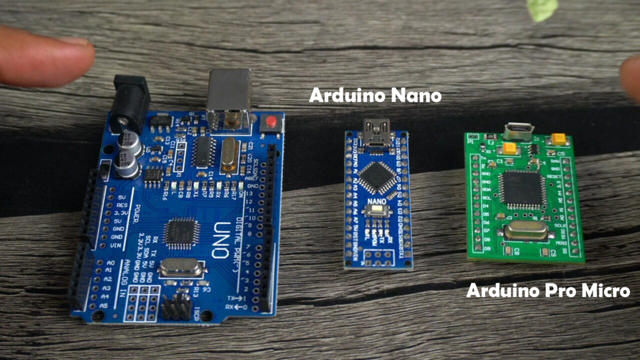
I have these three different types of Arduino boards; Arduino Uno, Arduino Nano, and this Arduino Pro Micro. Let me tell you, these are not the only Arduino boards. If you open the Arduino IDE; go to the Tools Menu and then to board you will see a long list of the Arduino boards.

So, technically you can start with any of these boards but what I suggest is; start with a board that’s easy to use.
Like for example take a look at those three Arduino boards. Which one is more users friendly? Think about it, I give you 5 seconds… You are right Arduino Uno is more users friendly and it’s easy to use; because it’s bigger in size, all the pins are clearly labeled, it has female headers for connecting sensors and breakout boards, and it also has a DC Female power jack for connecting DC adaptors.
Now, look at the Arduino Nano board, it doesn’t have the female headers, the Power jack, and its smaller in size and same is the Arduino pro Micro but it’s a little bit on the intermediate level side. Because in the Arduino Pro Micro you will have to burn a bootloader and then you can use it as a normal Arduino board. So, technically, if you have any of these boards, or even if you have the Arduino Mega, you can follow this Arduino course.
But, what I am trying to explain is, as a beginner you need to start with something that is super easy so that you don’t get discouraged. So, if you have not purchased the Arduino board, then get yourself Arduino Uno and if you can afford also get yourself an Arduino Nano.
Let me also tell you; all the programs that we can run on the Arduino Uno; we can also run them on the Arduino Nano without any issues.
Throughout this Arduino Course, I will keep switching between the Arduino Uno and Arduino Nano boards. I will also use these Arduino development boards to save some time.
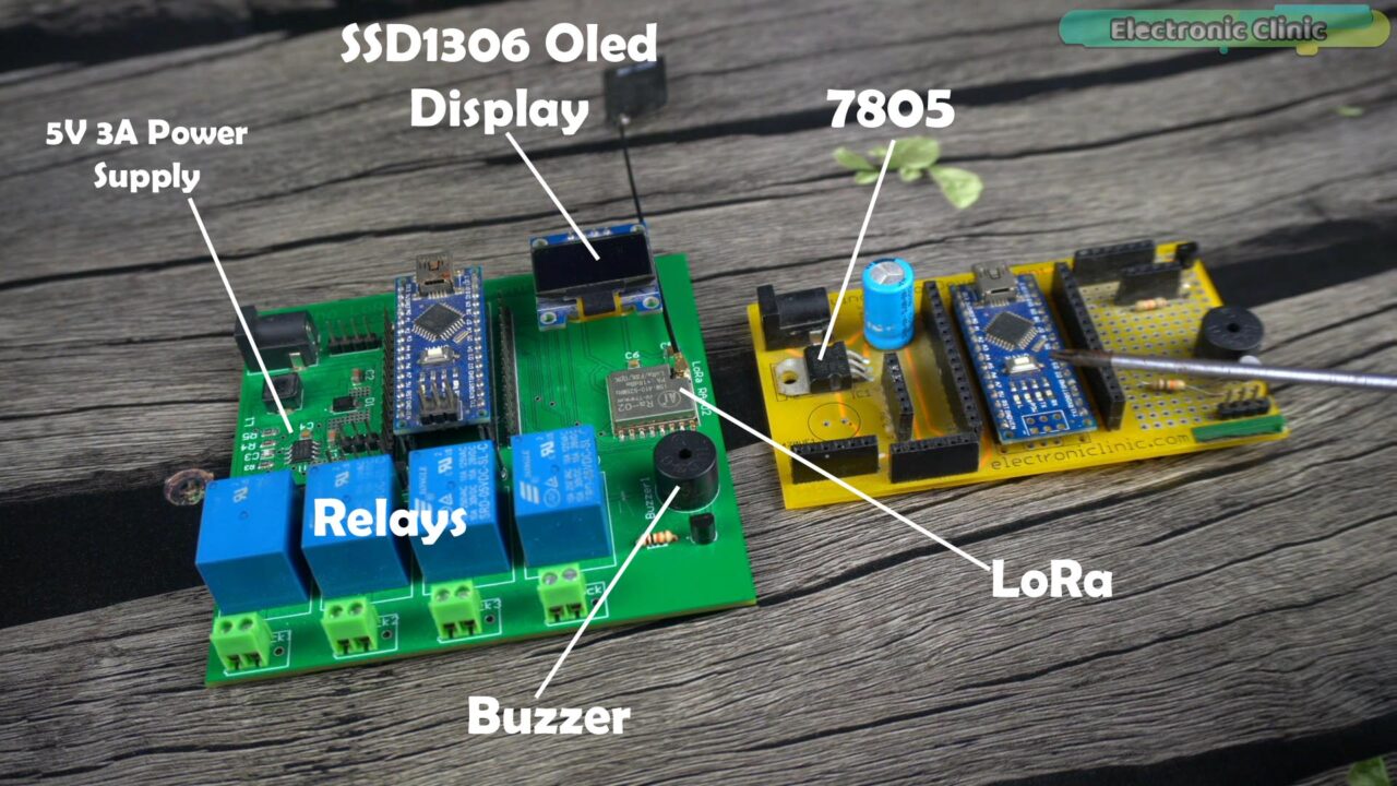
The development board on the right side is the basic one and it’s power supply is based on the 7805 voltage regulator. I am going to recommend this board for the absolute beginners because it’s easy to build as its quite easy to solder through-hole type components.
But if you have some electronics background and you know how to solder smd components then I am going to recommend make yourself the development board; which you can see on the left side. I designed this board in Altium Designer.
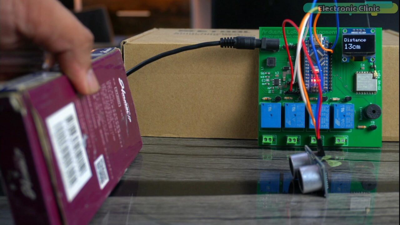
Anyway, you can see this board has the headers for interfacing input and output devices. It has an oled display module, a LoRa transceiver module for monitoring sensors and controlling loads over a long distance in the range of 1 to 5 kilometers, a 5V buzzer, relays, and a powerful regulated 5V and 3A power supply. So, I don’t have to manually wire up the most basic components when I am making and testing new projects. So, if you want to make this development board, you can read my article on the Arduino LoRa Development board. Or you can purchase a readymade Arduino development board. It will speed up your Arduino learning.
Anyway, right now, I am not going to talk about the technical specifications; because it’s something that you will automatically learn and moreover in the beginning I don’t want to scare you with technical stuff and you know it’s always quite boring. So, let’s just start with how to use Arduino Uno and Arduino Nano. So, without any further delay, let’s get started!!!
Amazon Links:
Arduino Nano USB-C Type (Recommended)
*Disclosure: These are affiliate links. As an Amazon Associate I earn from qualifying purchases.
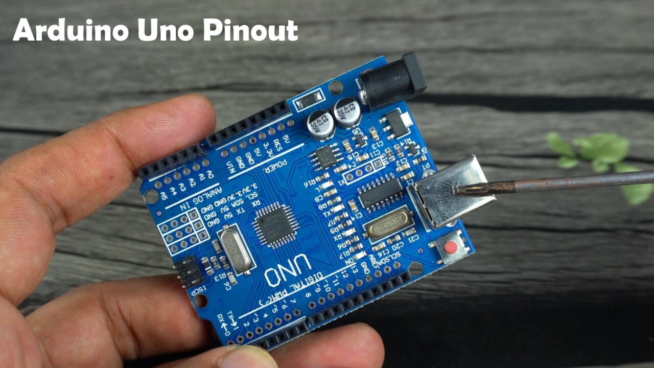
Arduino Pinout:
The Arduino boards I am using in this course are based on the Atmega328 microcontroller. It doesn’t matter if you see the dual in-line package type microcontroller or the SMD quad flat package. These are pre-loaded with the Arduino Uno 16MHz bootloader which allows us to program these controllers using the Arduino IDE. Anyway, let’s just focus on the Arduino Uno as it’s bigger in size and you might be able to see things clearly.
Reset Button:
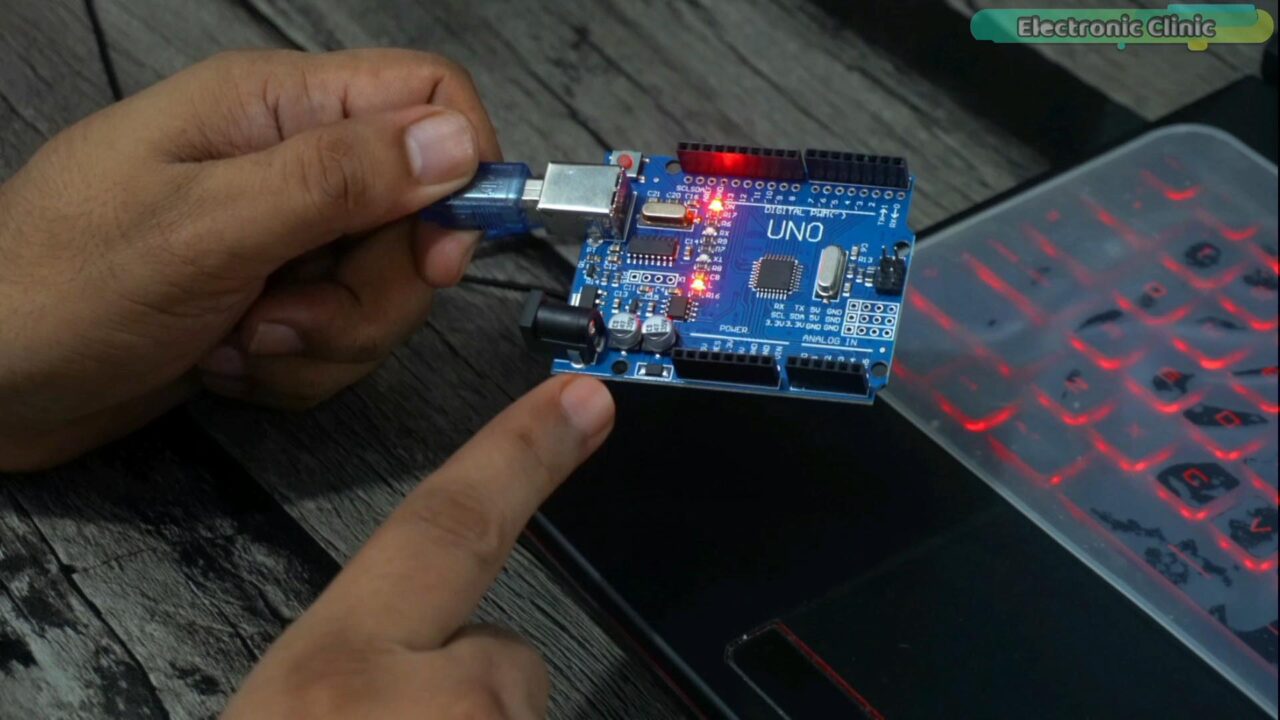
You can see a button next to the USB port, this is the Reset Button. This button allows you to manually reset the Arduino. So, when you press this button the board will restart means the code will start running from the beginning.
USB-Port:
This Type-B USB port on the Arduino Uno serves multiple purposes and it requires a Type-A to type-B USB cable to connect it to your computer.
This USB port is used to program the Arduino board. Simply, connect it to your computer using the USB cable, and then use the Arduino IDE “Integrated Development Environment” to write, compile, and upload your Arduino code to the board.
This USB port also serves as a power supply. When you connect it to the computer via USB, it draws power from the USB connection, and this way you can run your Arduino projects without the need for an external power supply, but you will have to make sure; the power requirements of your project are within the USB power limits. Otherwise, it will damage the USB port on your PC/Laptop.
This USB port also allows the users to establish serial communication between the computer and Arduino. For this, we have Serial Monitor in the Arduino IDE to communicate with the Arduino and debug our projects by sending and receiving data. Apart from the debugging, with the help of this USB port you can send data from the Arduino to desktop applications designed in Vb.net, C# sharp, Processing, Matlab, etc. You can check my playlist on the Desktop applications designing for the Arduino.
DC Power Jack:
The Arduino Board also has a DC power jack which is also known as the Barrel jack connector; it allows you to power up the Arduino board using an external power source with a voltage between 7V and 20V. The board has a 5V regulator that coverts input voltages greater than 5 volts. If the voltage is less than 7 volts the Arduino board may become unstable and if the voltage is greater than 13 volts, the voltage regulator may overheat and damage the board. So, the recommended range is 7 to 12 volts. You can use a 9V battery, a 3S Lipo or Lithium Ion Battery, or a 12V dry or Lead acid battery, or a 12V wall adaptor, etc.
For this Arduino course you don’t need an external power supply, but since I am explaining things so in some examples I will use the external power supply, just to make sure you get the idea how to externally power up the Arduino Uno and Arduino Nano.
You can see on the Arduino Nano board there is no DC Power jack, but we can still power it up using an external power supply. In a few seconds I am going to explain this.
Power Pins:
We have power pins on the left side of the Arduino board; clearly labeled with 5V, Reset, 3.3V, 5V, GND, GND, and VIN. The 5V are used to power the majority of the components on the Arduino board, including the microcontroller, sensors, and other breakout boards. The 5V regulator on the Arduino board is a 5V linear voltage regulator. The current handling capability of the voltage regulator depends on several factors, including
Whether you are using the original Arduino board or the clone. The one I have is not the original Arduino board. The official Arduino board uses the NCP1117 5V regulator and according to the datasheet its maximum continuous output current can range from approximately 800mA to 1A. However, this is just the maximum specified value under certain conditions.
Let me make it simple for you. If you are using sensors and breakout boards that draw current in the range of let’s 500mA to 600mA then you can use the onboard 5 volts. But if you are planning on using multiple servos, or Stepper motors, or a GSM module, etc then you will need to use an external 5V regulated power supply which can handle more current. So, this is the reason I built myself this Arduino Nano based development board; because it has a 5V and 3A power supply which is more than enough to power up multiple servos, GSM modules, etc. So, I don’t need to use an extra 5v power supply. Anyway, for this Arduino course, the onboard 5V is more than enough.
3.3V:
The Arduino Board also has a 3.3V voltage regulator, which provides a regulated 3.3 volts output. This voltage level is useful when you have components that require 3.3V instead of 5 volts.
GND:
We have a total of 3 ground points, two on the left side and the 3rd one on the right side. So, you can take a ground connection from any of the three points.
Vin:
Vin is the Voltage input. You can also connect your external power supply to the Vin pin on the Arduino. All you need is to connect the voltage wire to the Vin and Gnd wire to any of the GND pins.
This is how I did it on my designed Arduino development board. I have connected the 5V and 3A power supply output voltage and GND wires to the Vin and GND pins on the Arduino Nano.
Analog pins:
The Arduino Uno board has a total of 6 analog input pins, which are labeled A0 through A5. These analog input pins allow the Arduino to read analog voltage values from external sensors and devices. Each analog input pin can measure voltage in the range of 0 to 5 volts. Because, Arduino Uno is based on a 5V compatible controller board.
While the Arduino Nano has a total of 8 analog input pins, which are labeled A0 through A7. So, any program that is written for the Arduino Uno will also run on the Arduino Nano. But if you have written a code for the Arduino Nano in which you have used the analog pins A6 and A7 then that program won’t run on the Arduino Uno. Because on the Arduino Uno, A6 and A7 pins are not available.
Anyway, the A4 and A5 pins both on the Arduino Uno and Arduino Nano are also used as the I2C bus. A4 is the SDA and A5 is the SCL. I2C bus has the advantage of connecting multiple I2C supported sensors, displays, and other breakout boards using only two pins A4 and A5 on the Arduino.
So, if you are working on a project where you need to connect multiple sensor and breakout boards then you can purchase the sensors and boards that support I2C communication then this way you can save yourself a lot of IO pins on the Arduino.
Digital and PWM pins:
Arduino Uno has a total of 14 digital input/output pins, starting from 0 to pin 13. These pins serve various purposes and can be used for both digital input and output operations. Out of these 14 pins 6 are PWM pins.
Pins 0 and 1 are also labeled as RX and TX. Arduino Uno and Arduino Nano has only 1 serial port and you can use this for establishing serial communication with the PC and you can also connect devices like GSM, GPS, and bluetooth Modules etc that supports Serial communication.
Let me also tell you, as this is the default serial port, which is also used for uploading the program, so if any device is connected to these pins then you won’t be able to upload the program unless you turn off that device or remove the Tx and Rx wires. Once you have uploaded the program then you can reconnect the wires or you can turn on that device.
Now, you might be thinking what if I want to use two or three Serial communication supported devices like GSM, GPS, and Bluetooth all at the same time. Well, you can do it, you can use the softwareserial library for defining multiple serial ports. I have already covered this in my previous tutorials. Or, you can get yourself Arduino Mega that has multiple serial ports.
Next, we have pins 2 and 3. We can use these pins as simple Input/output pins. You can see this “ ~ “ symbol, it means pin 3 can also be used as the PWM pin. Besides this, these pins can also be used as external interrupt pins. These pins are capable of generating interrupts to the microcontroller when certain events occur, such as a change in voltage level or when a rising or falling edge is detected.
Similarly, pins 4 and 5 can be used as simple input/output pins. You can also use pin 5 as the PWM pin. Besides this, these pins have T0 and T1 timers.
Arduino Uno also has 1 SPI channel available on pins 10, 11, 12, and 13.
And let me also tell you,
- It has a 16Mhz Quartz Crystal oscillator.
- The Flash memory is 32KB out of which 0.5 KB is used by the bootloader.
- SRAM is 2KB “Dynamic Memory for data storage. and
- EEPROM is 1KB this is a non-volatile memory for storing data.
I think, I have talked much about the Arduino board and now we can start with the Arduino IDE.
Altium Designer, Altium 365, & Octopart:

Altium Designer is the world’s most trusted PCB design system. Altium Designer enables engineers to effortlessly connect with every facet of the electronics design process. Over 35 years of innovation and development focused on a truly unified design environment makes it the most widely used PCB design solution. With Altium Designer you can create PCB designs with an intuitive and powerful interface that connects you to every aspect of the electronics design process. Route it your way through any angle, tune for the delay, Push, Slide, and Walkaround faster than ever.
Easily work together with your mechanical team and forget about the days of swapping design files. Every design change stays in sync between Altium Designer and SOLIDWORKS, PTC Creo, Autodesk Inventor, Autodesk Fusion 360, or Siemens NX*.
Interact and collaborate with mechanical designers like never before in a photo-realistic, 3D design environment.
One of the best things about Altium Designer is that you can share your designs with your team members using Altium 365. They can check your design, leave comments, and if there are any issues, they can fix them from anywhere in the world. Altium Designer also uses the world’s fastest components search engine, Octopart, so you won’t have any difficulty in searching for components.
Altium Designer, Altium 365, and Octopart—unleashes the full potential of electronics design by seamlessly integrating design tools, collaboration platforms, and component databases. Together, they offer engineers a comprehensive and synchronized experience, leading to improved productivity, reduced errors, and accelerated innovation in the world of electronics design.
Arduino IDE:
The Arduino IDE (Integrated Development Environment) is the official software provided by Arduino to program and develop applications for Arduino boards. It is a user-friendly development environment that simplifies the process of writing, compiling, and uploading code to Arduino microcontrollers. You can also use the Arduino IDE for programming ESP32 WiFi + Bluetooth Module, ESP8266, Raspberry Pi Pico, and STM32 microcontroller boards etc.
To get started with the Arduino IDE, you will need to download and install it from the official Arduino website.

For now forget about the buttons and menus, because you will practically see everything in action. Anyway, when you open the Arduino IDE, you will see these two functions. The void setup() function and the loop() function.
Void means these functions have no return types and as you can see the parenthesis are empty which means they are not taking any arguments as the inputs.
setup() function:
The code inside the setup() function is executed only once when the Arduino is turned ON or when it resets. The purpose of the setup() function is to setup the initial configuration and initialization of the Arduino board and its peripherals before the main program execution begins.
So, the setup() function typically contains code that initializes various settings and states for pins, sensors, communication modules, and other components used in the Arduino project.
It’s just like an introduction. We tell the controller which pin is going to be used as the input and which pin is going to be used as the output. If I want to use the Serial communication then I will have to activate it first, and then I will set the baud rate. Same thing applies to the I2C, SPI, etc.
loop() function:
The code that’s meant to be executed repeatedly is placed in the loop() function.
In this function, you can include the main logic of your program, read sensors, control outputs, and perform other tasks that need to be repeated in a loop as long as the Arduino board is powered on or until the program is interrupted.
Enough with the talking and now Let’s go ahead and start with our first LED blinking project.
Arduino Projects for Beginners:
Arduino Led Blinking Example 1:
In this first example we are going to control the Arduino’s onboard LED connected to the digital pin D13. Arduino Nano also has this LED connected to the same pin13. So, for this first example, you don’t need to connect an external LED. So, let’s go ahead and connect the Arduino board to the Laptop.
Arduino Led Blinking Code:
I have written three programs which have the same purpose of blinking the onboard LED. So, let’s start with the first program.
|
1 2 3 4 5 6 7 8 9 10 |
void setup() { pinMode(13, OUTPUT); } void loop() { digitalWrite(13, HIGH); delay(3000); digitalWrite(13, LOW); delay(1000); } |
This is the simplest LED blinking code. No doubt it follows all the rules. Inside the setup() we tell the controller to set the digital pin13 as the output because LED is an output device. And then in the loop() function we turn it ON and OFF. Isn’t so rude? It feels like if you call someone for a certain job and when he arrives and you don’t even bother about asking his name or introducing him to the manager etc. And you just tell him start working.
The same thing is happening over here. You are not supposed to write a program like this. Now, you might be thinking why? Imagine you have used multiple LEDs for creating some cool animations and for some reason, you decide to change the pin numbers. However, those pins are used all over the code.
And what if those LEDs have different colors and you want to control a specific color LED. So, programs like these don’t make any sense. Let’s take a look at another program.
|
1 2 3 4 5 6 7 8 9 10 11 12 |
int device = 13; void setup() { pinMode(device, OUTPUT); } void loop() { digitalWrite(device, HIGH); delay(3000); digitalWrite(device, LOW); delay(1000); } |
This is the same program, but this time I have properly defined the pin. I call it device. Now, if I want to change the pin number; I can change it over here. But, still this program is not good. You know this program is for blinking the onboard LED, because I told you. What if I ask someone what is the purpose of this code. His first question would be what is this device? Because, this device could be anything, it could be a relay, it could be a buzzer, or it could be a motor or something else.
So, what I am trying to explain is give it a meaningful name and add a little bit of information. Let’s take a look at another program and you will get the idea.
|
1 2 3 4 5 6 7 8 9 10 11 12 13 14 15 16 17 18 19 20 21 22 23 |
/* * Arduino Led Blinking Project * By: Engr. Fahad * https://www.electroniclinic.com/ */ int led = 13; // i am going to control the Onboard led connected to pin 13 int led2 = 12; String fahad; void setup() { // put your setup code here, to run once: pinMode(led, OUTPUT); } void loop() { // put your main code here, to run repeatedly: digitalWrite(led, HIGH); // Turn On the LED delay(3000); // 3 seconds delay, 1000ms = 1sec digitalWrite(led, LOW); // Turn OFF the LED delay(1000); // 1 second delay } |
Your program should be like this because it’s easy to read this program. If I send it to someone who knows about the Arduino programming; in just 5 seconds he will completely understand the purpose of this program because everything is well commented. So, let me explain this code and the rules.
Let’s start with comments. Comments are optional and it’s totally up to you whether you want to use them or not. But it’s a good programming practice to add comments in your programs because it makes your programs more understandable. We have two types of comments single-line comments and multi-line comments. The one on the top is a multi-line comment. To add a multi-line comment, you simple right the forward slash followed by an asterisk, and then write anything you want. To end a multi-line comment simply write the asterisk and forward slash. So, anything written in between these is completely ignored by the compiler.
To write a single-line comment simply put two forward slashes and start typing anything you want. It has nothing to do with the actual code.
While defining a pin number or any variable you need to follow some rules.
- No special characters are allowed in the beginning of a variable name.
- No numbers are allowed in the beginning.
- No spaces are allowed.
- You can use Underscore as the space.
- A variable name should be unique. You are not allowed to use a single name for multiple pins and you can’t define a single variable name with different data types. Think about yourself, your name is unique among your brothers and sisters. What if all had the same name? So, a variable name should be unique.
- It should be meaningful. As I am controlling an LED so I defined Pin 13 as LED. I could also write it as onboard_led. So, what I am trying to explain is select a name that is unique and meaningful.
So, after defining the pin, next, in the setup() function we will need to tell the controller whether we want to use it as an input for monitoring some kind of a sensor or as an output to control something. We know that LED is an output device so we are going to set it as output and for this we use the pinMode() function. This is the built-in function you can see it has a different color. You are not allowed to use a built-in function as a user-defined function. And you might know it’s a case sensitive language so the M should be capital, you have to use the built-in functions and all the keywords as it is. You are not allowed to change even a single character; otherwise it will generate an error.
The actual code which is supposed to run repeatedly is kept inside the loop() function. To turn ON/OFF any IO pin on the Arduino we use the digitalWrite() function. Its also a built-in function and it takes two arguments as the input the pin and the command HIGH or LOW.
Then there is a delay of 3 seconds. Then I have turned OFF the LED and again there is a delay of 1 second.
Now, to check for any errors click on the verify button, it will compile the code for you, if you see any error, fix it. “Watch video tutorial for step by step explanation“ While the Arduino Uno board is connected to the PC, go to the Tools Menu then to board and select your desired Arduino board, In my case I am going to select Arduino Uno. Again go to the Tools Menu and this time select the communication Port. Now, you can click on the Upload button.
The onboard LED will start blinking now you can try different delay values.
Arduino External LEDs, Example 2:
In this 2nd example, we are going to control 2.5V and 10mA Leds. Controlling an external LED is just like controlling the onboard LED. Now, you might be thinking then why am I explaining this? Well, I want to explain how to use other IO pins, how to define and use multiple pins at the same time, and how to calculate the current limiting resistor.
The Arduino Uno and Arduino Nano both are 5V compatible controller boards. Which means 5V are available on its IO pins when turned ON. So, if you will directly connect 2.5V LEDs with the Arduino; they will burnout in a second.
So, how to control a 2.5V LED with a pin that has 5V. Well, We will have to use a current limiting resistor and for this we will have to perform some calculations. So, let’s do it.
The LED Voltage is 2.5V and the LED Current is 10mA.
Voltage on the Arduino Pin is 5V.
So using the V = IR formula, we can find the Resistor value which is 250 ohms.
Don’t select a resistor with a value less than 250 ohms. Go for a slightly bigger value this will increase the LED life span. The LED won’t heat up. I always select 330 ohm resistor it works perfectly.
Led Interfacing with Arduino:
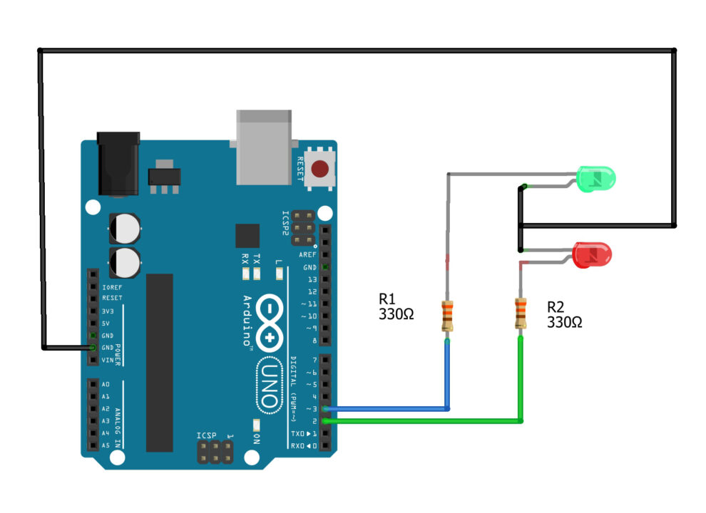
Connect the Cathode legs of the LEDs together and then connect it to the GND pin on the Arduino board. Connect the Anode legs of the LEDs to the digital Pins 2 and 3 on the Arduino through these 330ohms current limiting resistors. Now, let’s go ahead and take a look at the programming.
Arduino External Led Programming:
|
1 2 3 4 5 6 7 8 9 10 11 12 13 14 15 16 17 18 19 20 21 22 23 24 25 26 27 |
/* * Example 2: External Leds * https://www.electroniclinic.com/ */ int led1 = 2; int led2 = 3; void setup() { // put your setup code here, to run once: pinMode(led1, OUTPUT); pinMode(led2, OUTPUT); } void loop() { // put your main code here, to run repeatedly: digitalWrite(led1, HIGH); delay(1000); digitalWrite(led2, LOW); delay(1000); digitalWrite(led2, HIGH); delay(1000); digitalWrite(led1, LOW); delay(1000); } |
This program is quite similar to the program used in example number1. The only difference is that this time I am using two LEDs connected to digital pins 2 and 3. Since, I am using the same color LEDs so I named them led1 and led2. And if I was using different color LEDs; for example Red and Green, then I could also call these LEDs as R_led and G_led. Anyway, the pins are defined.
In the void setup() function, I have set both the Pins as output, and in the void loop() function I am simply turning ON and turn OFF these LEDs. Let’s verify the code to check for any errors… You can see there are no errors and now we can upload the program.
For this go to the Tools Menu…then to board and select the Arduino Uno. Again go to the Tools menu and this time select the port, and finally, click on the Upload button. The two Leds will start blinking. For the step by step explanation and practical demonstration watch the video tutorial given at the end of this article.
Arduino Digital Input, Example 3:
In this 3rd example, I am going to explain how to read a digital signal on any IO Pin on the Arduino. A digital signal may be 0 or 1 and you should be able to read both the types; because there are different types of sensors in the market. Some sensors give 1 at the output while others give 0. Anyway, you will get the idea as we cover different examples. For now let’s concentrate on how to read a button click.
Now, in this example, I am going to use Arduino Nano but you can also use Arduino Uno.
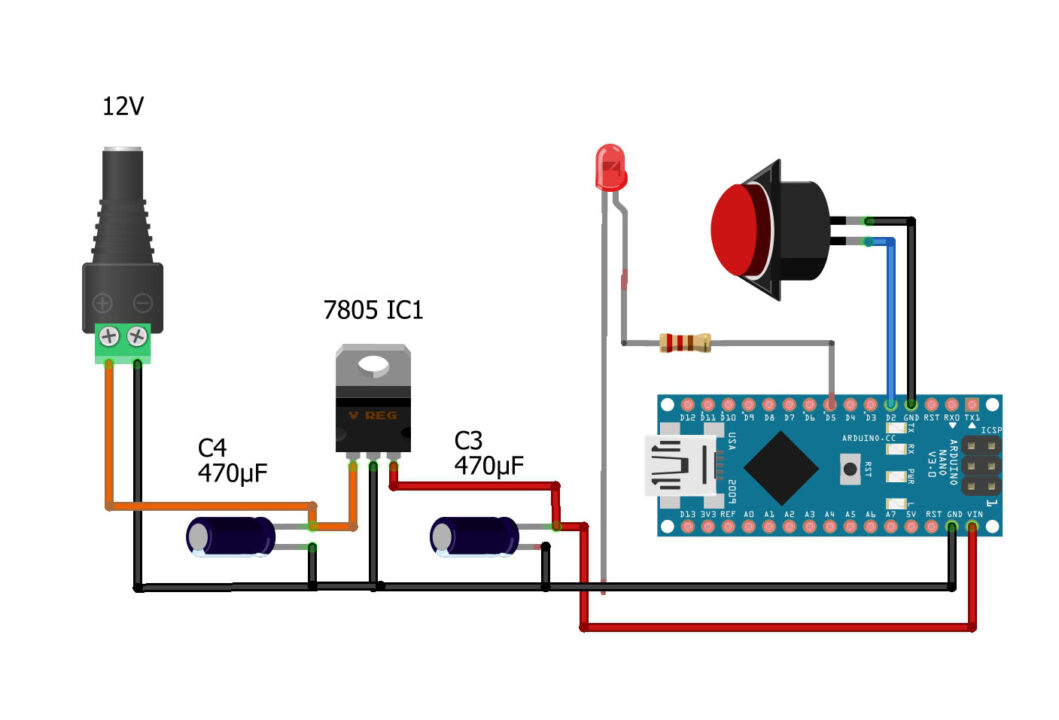
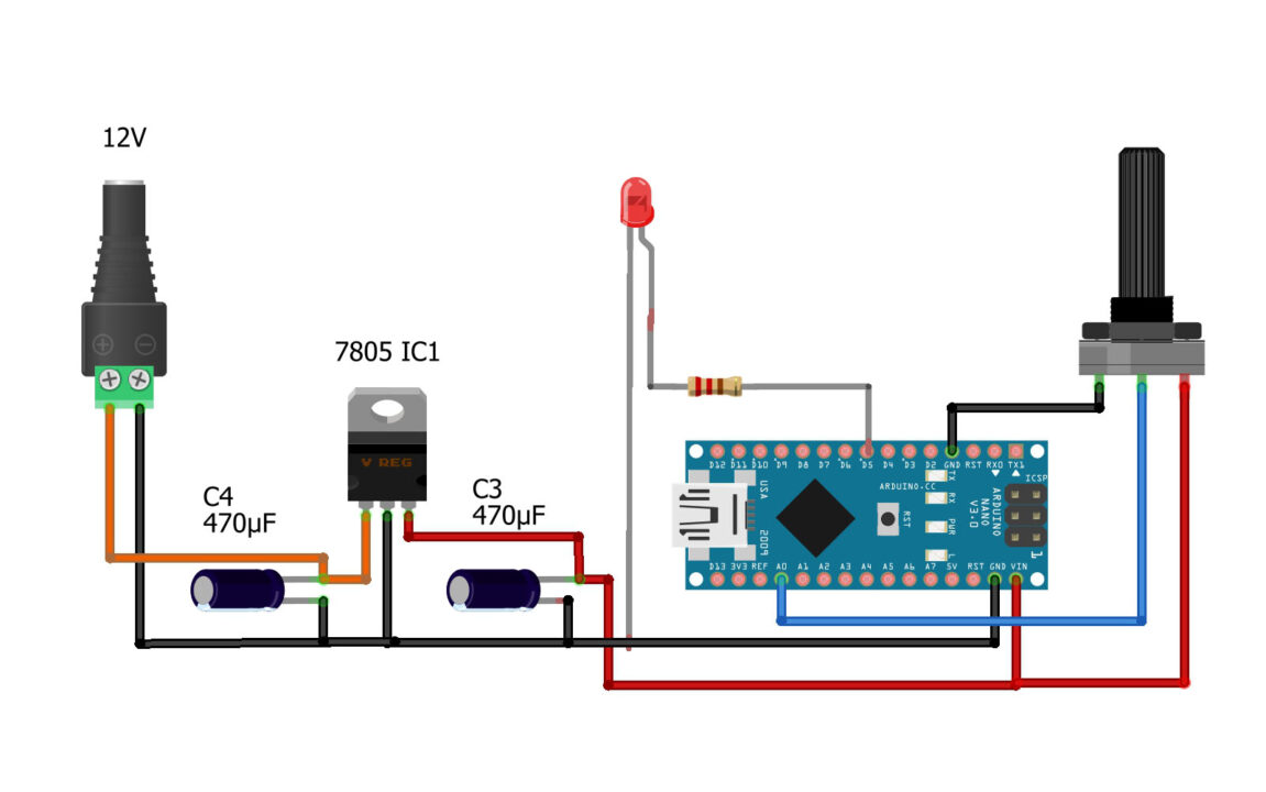
One side of the button is connected to the ground and the other side of the button is connected to the digital pin 2. On the Arduino we don’t need to add a pull-up resistor; because it already has, we only need to enable it; which I will explain in a minute. Anyway, this time I added an LED to the digital pin 5. The power supply on the left side is optional. If you are using your laptop or PC to power up the Arduino then there is no need for an external power supply. But, if you want to externally, power up your Arduino board then you can built yourself this basic 5V regulated power supply based on the 7805 voltage regulator. Let me tell you this not a powerful power supply, you can only use it with basic sensors and 5V relays. Anyway, let’s go ahead and take a look at the programming.
Arduino Digital Input Programming:
|
1 2 3 4 5 6 7 8 9 10 11 12 13 14 15 16 17 18 19 20 21 22 23 24 25 26 27 28 29 |
/* * Arduino Example 3: Digital Input " Push Button" * https://www.electroniclinic.com/ */ int led = 5; //Output, an LED is connected to the digital pin 5. int button = 2; // Input, push button. void setup() { pinMode (led, OUTPUT); pinMode (button, INPUT_PULLUP); //internal pullup resistor is enabled. } void loop() { if(digitalRead(button) == LOW) { digitalWrite(led, HIGH); delay(1000); } if(digitalRead(button) == HIGH) { digitalWrite(led, LOW); delay(1000); } } |
I started off by defining the pins for the Led and Push button exactly the same way as previously explained.
In void setup() function I set the Led as output and I set the button as Input.
When connecting a sensor or a button to a pin configured with INPUT_PULLUP, the other end should be connected to the ground. In the case of a simple switch, this causes the pin to read HIGH when the switch is open, and LOW when the switch is pressed. This is exactly what I did. The two legs of my push button are connected to the GND and pin 2 on the Arduino.
In the void loop() function, I have added two conditions to check if the button is pressed or the button is open. To read a digital signal on any IO pin on the Arduino we use the digitalRead function.
The first condition means, check if a low signal is available on the pin 2. So, if it reads a low signal then it means the button is pressed. And if the button is pressed then we tell the controller to turn ON the Led. And when the button is released or when the button is open; simply turn OFF the Led.
After uploading the program, you will be able to control the LED using a Pushbutton. For the step by step explanation and practical demonstration watch the video tutorial given at the end of this article.
Arduino Analog Input, Example 4:
In this 4th example, I am going to explain how to read an analog sensor and send its value to the Serial monitor. So, in this example, we are going to cover two things, how to read an analog sensor and how to use Serial Communication. For the demonstration purposes I am going to use the Potentiometer as the analog sensor, if you want you can also use an LDR or any other analog sensor.
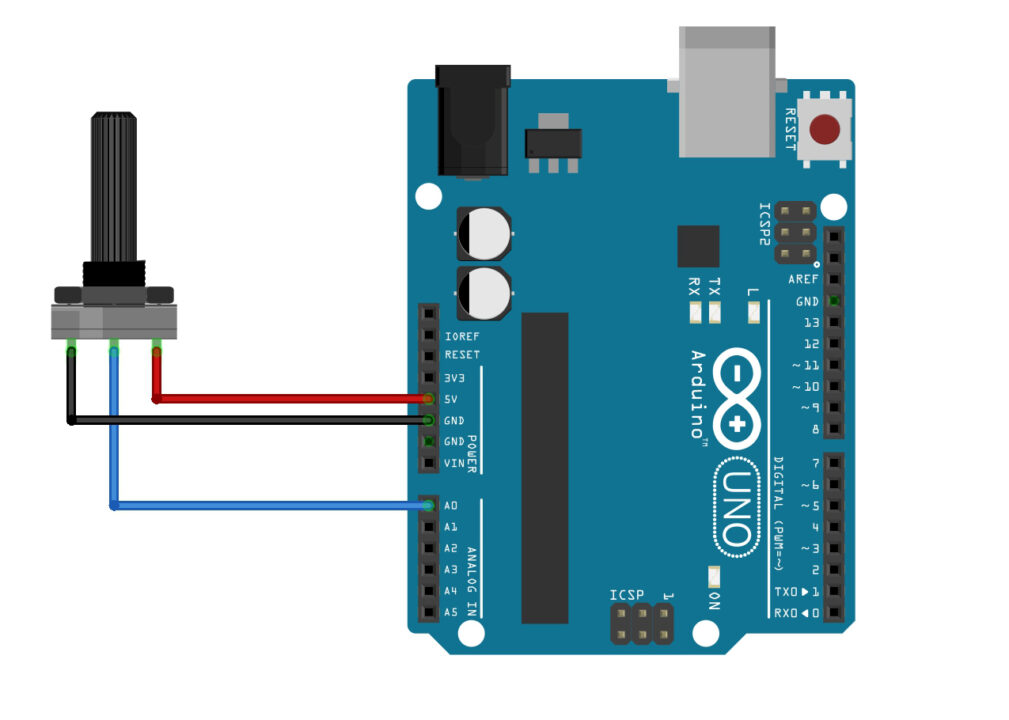
The Leftmost and rightmost legs of the potentiometer are connected to the Arduino 5V and GND. Whereas the middle leg of the potentiometer is connected to the Analog pin A0. Now, let’s go ahead and take a look at the programming.
Arduino Analog Input programming:
|
1 2 3 4 5 6 7 8 9 10 11 12 13 14 15 16 |
o Analog Input programming: int pot = A0; // Potentiometer is connected to the Analog pin A0 int potvalue; // a variable that stores the Pot value. void setup() { // put your setup code here, to run once: Serial.begin(9600); // This enables the serial port, 9600 is the Baud Rate. pinMode(pot,INPUT); } void loop() { // put your main code here, to run repeatedly: potvalue=analogRead(pot); // we use analogRead function for reading analog sensors Serial.println(potvalue); // This instruction sends the Potentiometer value to the Serial Monitor } |
I simply started off by defining the pin and a variable. To activate Serial communication between Arduino and a computer or any other serial communication supported devices; we use the Serial.begin() function and inside the parenthesis we add the Baud rate. For this example, I have selected the standard baud rate of 9600. The baud rate specifies the speed at which data is transmitted in bits per seconds(bps). Common baud rates include 9600, 115200, 57600, 38400, etc.
analogRead() is a function used to read analog voltage values from an analog input pin on the Arduino board. Arduino boards have several analog input pins labeled with “A0,” “A1,” and so on. These pins can be used to read analog signals, such as those generated by sensors, potentiometers, or other analog devices.
The analogRead() function takes one argument, which is the number of the analog input pin you want to read from. The argument should be a number representing the pin’s analog input number. For example, to read from analog pin A0, you would use analogRead(A0). But, in my case, I have defined it with the name pot.
So, it reads the potentiometer and stores the value in a variable potvalue and then using the Serial.println() function we send the value to the Serial Monitor.
Upload the program and then click on the Serial monitor button.
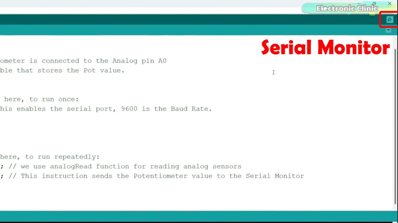
Then you should be able to see the Potentiometer value; you will see different values as you rotate the knob of the Potentiometer. For the step by step explanation and practical demonstration watch the video tutorial given at the end of this article.

Now, let’s move on to the next example.
Arduino PWM, Example 5:
In example #5, I am going to explain how to control the brightness of an LED using a potentiometer. For this example, you can use any PWM pin on the Arduino. In my case, I am using the digital pin 5 which is also a PWM pin. Let me explain the connections.
Potentiometer is still connected to the Analog Pin A0, I explained this in example #4, and the LED is connected to Pin5 through this 330 ohm currently limiting resistor. Now let’s go ahead and take a look at the programming.
Arduino PWM Programming:
|
1 2 3 4 5 6 7 8 9 10 11 12 13 14 15 |
int ledPin = 5; // LED connected to digital pin 5 which is also a PWM pin. int analogPin = A0; // Potentiometer is connected to the analog pin A0 int val = 0; // variable to store to potentiometer value void setup() { pinMode(ledPin, OUTPUT); // sets the pin as output pinMode(analogPin, INPUT); } void loop() { val = analogRead(analogPin); // read the input pin val = map(val, 0, 1023, 0, 255); analogWrite(ledPin, val); // analogWrite values from 0 to 255 } |
I defined the pins and variables using the same rules as I explained in example #1. Anyway, in this example the instructions are pretty much the same except these two instructions.
map() function is a useful function that is used to scale (or map) a value from one range to another. It takes an input value and scales it proportionally to a new range. This function is particularly handy when you want to convert sensor readings or other values to a different scale that is more suitable for your application. You know the duty cycle should be between 0 and 255. So that’s why I converted the Potentiometer value from 0 to 1023 into 0 to 255. You can use the same technique for setting the motor speeds and you can also use this technique for expressing the sensor values in percentage. So, it depends on your logic how you use it.
Unlike the analogRead() function that is used for reading analog values, analogWrite() function is used for generating analog-like output on certain pins. However, it’s important to note that not all pins on the Arduino board supports PWM. On most Arduino boards, the pins that support PWM are marked with this “~” symbol next to the pin number.
The analogWrite() function takes two arguments: the first argument is the pin number you want to generate the PWM signal on, and the second argument is the value of the duty cycle. The duty cycle value should be between 0 (fully off) and 255 (fully on).
After uploading the program you will able to control the LED brightness. For the step by step explanation and practical demonstration watch the video tutorial given at the end of this article.
Now, let’s move on to the next example.
Arduino 16×2 LCD, Example 6:
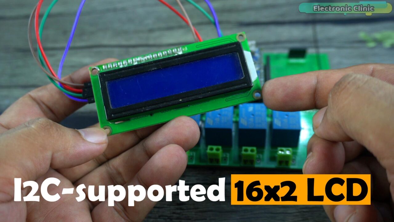
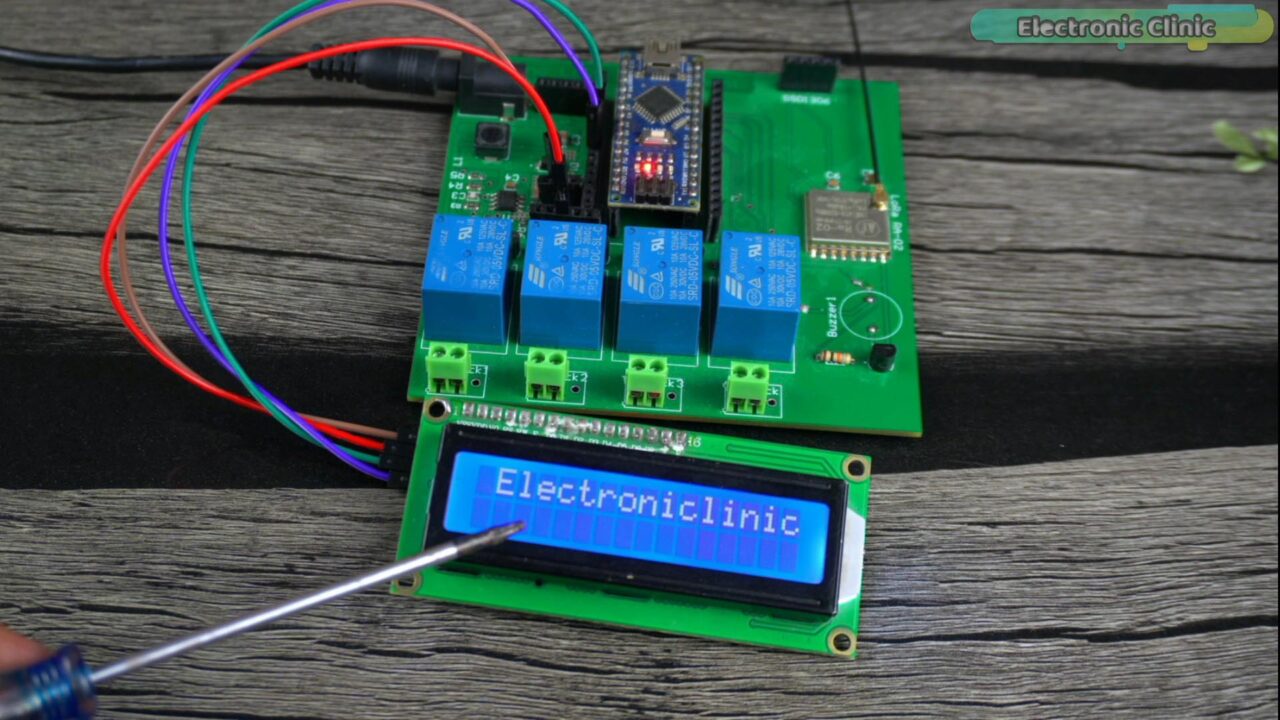
In example #6, I am going to explain how to print a text message on an I2C supported 16×2 LCD. This is the most commonly used LCD and you are going to need this LCD in your upcoming projects for printing text messages and sensors values, and for creating menus etc.
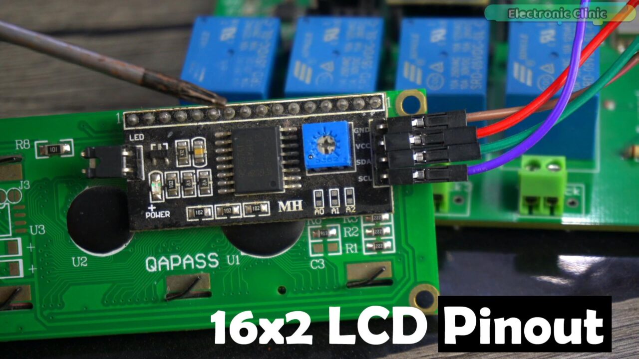
Anyway, this is the i2c version of the 16×2 LCD because it has this driver on its backside so you don’t need to connect a lot of wires. You only need to use 4 wires. All the 4 pins are properly labeled with GND, VCC, SDA, and SCL.
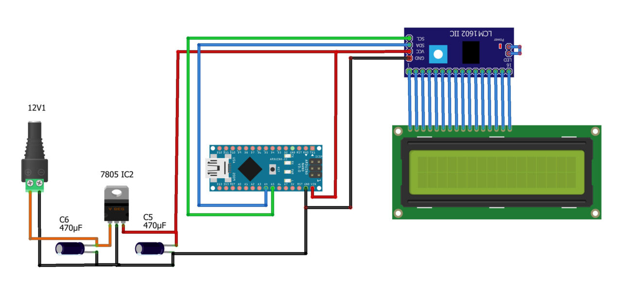
Simply connect the VCC and GND pins to the Arduino 5V and GND pins; and connect the SDA and SCL pins to the Arduino A4 and A5 pins. A4 is the SDA and A5 is the SCL. I have already explained this. It also has a blue color potentiometer to control the LCD contrast or brightness. Now let’s go ahead and take a look at the programming.
Arduino 16×2 LCD Programming:
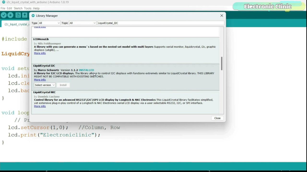
Before, you start the programming, first of all, make sure you have installed the LiquidCrystal library. For this simply copy this name” LiquidCrystal_I2C”. Then go to the Sketch menu > then Include Library and click on the manage libraries. Paste the library name in the search box. You can see I have already installed this library and you also need to install the same library.
Programming:
|
1 2 3 4 5 6 7 8 9 10 11 12 13 14 15 |
#include <LiquidCrystal_I2C.h> LiquidCrystal_I2C lcd(0x27,16,2); void setup() { lcd.init(); lcd.clear(); lcd.backlight(); // Make sure backlight is on } void loop() { // Print a message on both lines of the LCD. lcd.setCursor(1,0); //Column, Row lcd.print("Electroniclinic"); } |
So, I started off by adding the LiquidCrystal_I2C.h header file.
This line initializes an instance of the LiquidCrystal_I2C class named lcd. The constructor takes three arguments:
0x27 is the I2C address of the LCD module. The specific address may vary depending on the configuration of your LCD module. You can find the I2C address by running an I2C scanner sketch which you can download from the article.
16 is the number of columns in the LCD and 2 is the number of rows in the LCD.
In the void setup() function,
The lcd.init() function initializes the LCD by sending the necessary commands over the I2C bus.
The lcd.clear() function clears the LCD screen, making sure it’s empty or blank.
The lcd.backlight() function turns ON the backlight; if the LCD module has it. If your LCD doesn’t have backlight support then this command will not affect the display.
The lcd.setCursor() function is used to select one of the two rows and 16 columns. The first number is used to select the column, in my case I have selected column 1, the index starts from 0 all the way to 15.
The 2nd number is used to select the row, 0 means first row and 1 means 2nd row. In my case I have selected the first row. Now, after selecting the column and row next we use the lcd.print command to write text on the LCD. Make sure you use double quotes for printing strings. If you want to display numbers and variable data on the LCD then there is no need to use the double quotes, just write the variable name or number and that’s it.
For the step by step explanation and practical demonstration watch the video tutorial given at the end of this article. Now, Let’s move on to the next example.
Arduino Oled Display, Example 7:
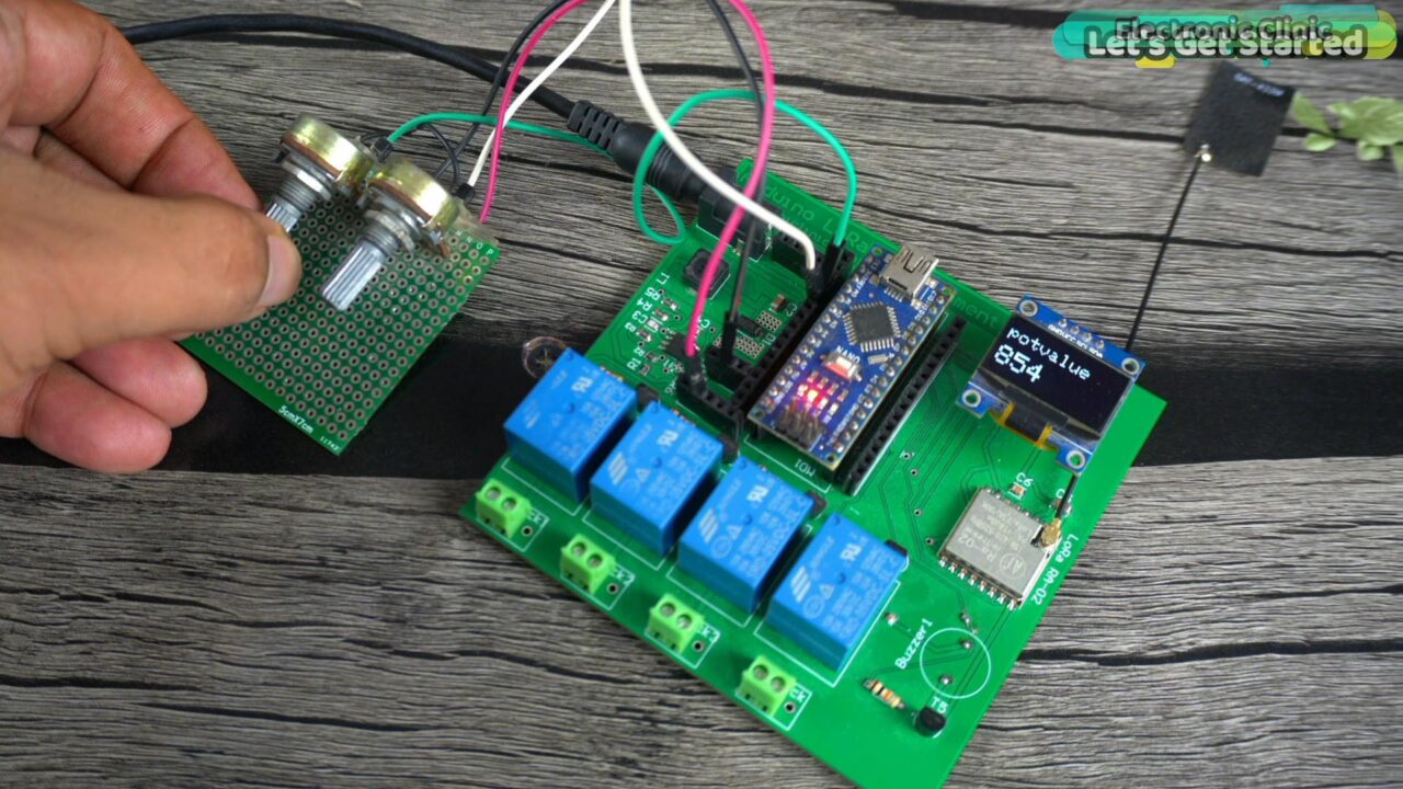
In this 7th example, I am going to explain how to use an I2C supported SSD1306 Oled display module with the Arduino. For the demonstration purposes, I am going to print the Potentiometer value on the Oled display module.
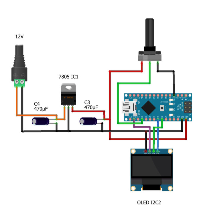
Potentiometer is still connected to the analog pin A0. The VCC and GND of the Oled display module are connected to the Arduino 3.3V and GND pins. Whereas the SDA and SCL pins of the Oled display Module are connected to the Arduino Analog pins A4 and A5 respectively. A4 is the SDA and A5 is the SCL. Now, let’s go ahead and take a look at the programming.
Arduino Oled Display Programming:
For the SSD1306 Oled display module first you will need to install the libraries and then you can use the header files. For this simply go to the Sketch Menu, then to Include Library and click on the manage libraries. Type Adafruit_GFX in the search box and install it.
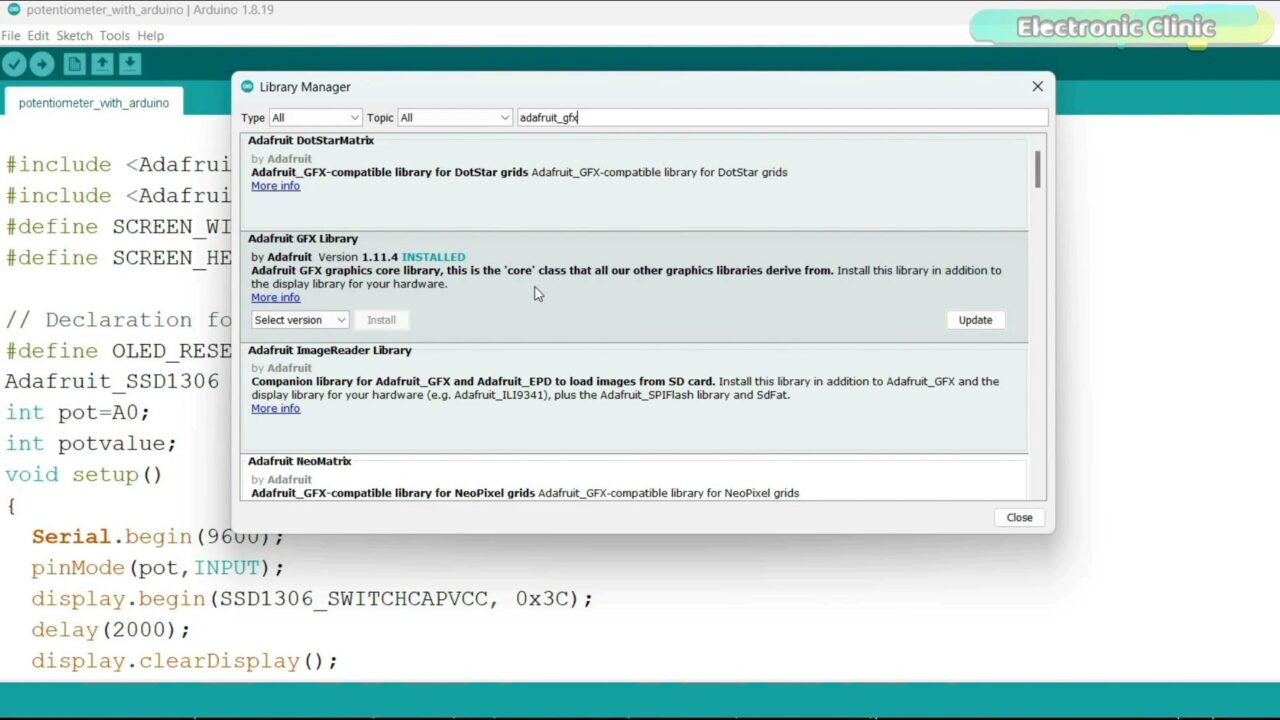
As you can see I have already installed this library. Next, search for the Adafruit_SSD1306 and install it.
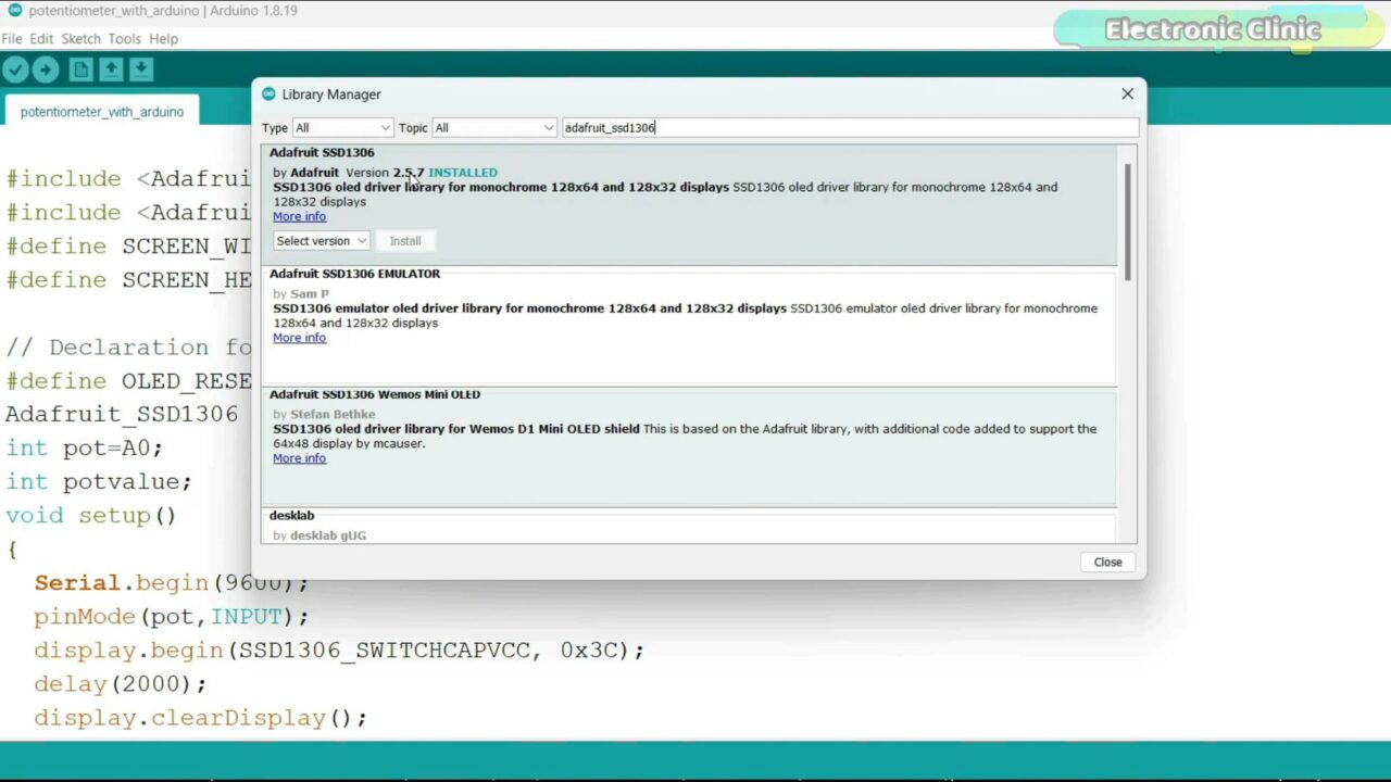
As you can see I have also installed this library.
Programming:
|
1 2 3 4 5 6 7 8 9 10 11 12 13 14 15 16 17 18 19 20 21 22 23 24 25 26 27 28 29 30 31 32 33 34 35 |
#include <Adafruit_GFX.h> #include <Adafruit_SSD1306.h> #define SCREEN_WIDTH 128 // OLED display width, in pixels #define SCREEN_HEIGHT 64 // OLED display height, in pixels // Declaration for an SSD1306 display connected to I2C (SDA, SCL pins) #define OLED_RESET -1 // Reset pin # (or -1 if sharing Arduino reset pin) Adafruit_SSD1306 display(SCREEN_WIDTH, SCREEN_HEIGHT, &Wire, OLED_RESET); int pot=A0; int potvalue; void setup() { Serial.begin(9600); pinMode(pot,INPUT); display.begin(SSD1306_SWITCHCAPVCC, 0x3C); delay(2000); display.clearDisplay(); display.setTextColor(WHITE); delay(10); } void loop() { potvalue=analogRead(pot); display.clearDisplay(); display.setTextSize(2); display.setCursor(0, 10); display.print("potvalue"); display.setTextSize(3); display.setCursor(0, 35); display.print(potvalue); display.display(); delay(100); } |
I started off by adding the header files.
Next, I defined the Width and Height of the Oled display module. The type of the Oled display module I am using doesn’t have a reset pin so that’s why the OLED_RESET is set to -1.
Adafruit_SSD1306 display(SCREEN_WIDTH, SCREEN_HEIGHT, &Wire, OLED_RESET);
This line initializes an instance of the Adafruit_SSD1306 class named display. The constructor takes four arguments.
Potentiometer is connected to the Analog pin A0 named as pot and the potvalue variable is going to store the value of the potentiometer.
In the void setup() function, you can see I have activated the Serial communication and this time round I only used it for the debugging purposes. The potentiometer is set as INPUT. This line activates the Oled display module. 0x3C is the I2C address you can use the I2C scanner code to find this address. You can download that code from the Article. Anyway, then we clear the display and set the text color to white.
In the void loop() function, we simply read the Potentiometer and store its value in the variable potvlaue and then using these instructions we print this text and value on the Oled display Module. You can set the font size, and using the setCursor you can select any position, and using the display.print() function you can print strings and numbers on the Oled display module.
For the step by step explanation and practical demonstration watch the video tutorial given at the end of this article. Now, let’s move on to the next example.
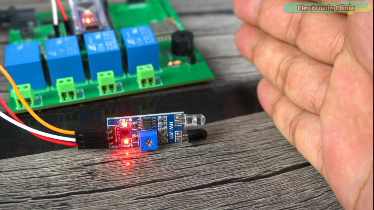
Arduino IR Sensor & Buzzer, Example 8:
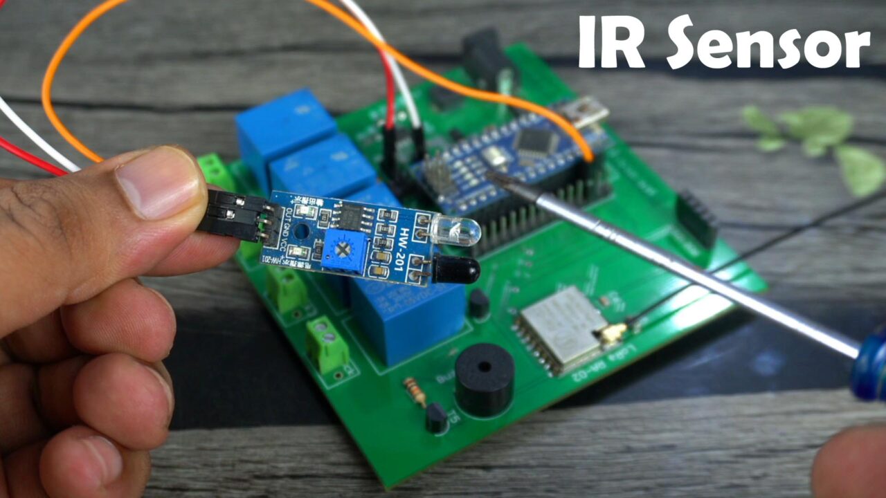
In this 8th example, I am going to explain how to use an IR sensor and Buzzer with the Arduino. You will need an IR sensor like this for obstacle detection, for making security systems, for making line following robots, and even for making contactless control systems like for example a doorbell etc.
In this example, what I want to do is, I want the buzzer to turn ON when the IR sensor detects any object. Instead of controlling a buzzer, you can also control a relay to control high voltage AC and DC loads.
Anyway, this IR sensor has these two Infrared Leds, this white LED is used as the transmitter and this Black color LED is used as the receiver. It transmits the infrared light which reflects from an object and when the receiver LED detects the reflected light, it knows there is something in front of the sensor, and then it signals the Arduino.
This IR Sensor also has a Blue color Potentiometer which is used to set the range. It offers a long range when used against white color and reflective objects and it offer shorter range when used against black objects. That’s why the IR sensors are most frequently used in line follower robots. And you might have seen the black lines are usually drawn on a white paper or a surface that’s more reflective than the Black color.
This IR sensor has a total of three wires which are clearly labeled with VCC, GND, and OUT.
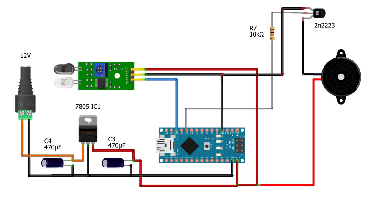
Connect the VCC and GND pins to the Arduino 5V and GND. Connect the Out pin to the Arduino Pin D10.
The buzzer is connected to the Arduino Pin D8 through a driver circuit consisting of 2n2222 NPN transistor and a 10Km resistor. And now let’s go ahead and take a look at the programming.
Arduino IR Sensor Programming:
|
1 2 3 4 5 6 7 8 9 10 11 12 13 14 15 16 17 18 19 20 21 22 23 24 25 26 |
int buzzer = 8; // 5V buzzer is connected to the Arduino pin D8 int irpin = 10; // The 5V IR Obstacle sensor is connected to the Arduino pin D10 int irstatus = HIGH; // stores the status of the IR Sensor in the form of 1 and 0 void setup() { Serial.begin(9600); // Activates Serial communication pinMode(buzzer, OUTPUT); // Buzzer is output device pinMode(irpin, INPUT); // Ir Sensor is an Input Device } void loop() { irstatus = digitalRead(irpin); // Reads a digital signal 5V or Gnd on the Arduino pin D10 if (irstatus == LOW) { // The type of IR Sensor i am using outputs 0 when it detects an object digitalWrite(buzzer, HIGH); // Turn on the Buzzer delay(2000); // two seconds delay digitalWrite(buzzer, LOW); // turns OFF the buzzer } else { // if there is nothing in front of the IR sensor digitalWrite(buzzer, LOW); // keep the buzzer off. } delay(200); } |
I already explained 7 examples and I am sure now you can read this program and I am sure now you fully understand how to define variables and how to use these built-in functions.
Anyway, this program is quite similar to the digital input example in which I used a push button for reading the button clicks. And in that example I clearly explained about different sensors that gave 0 or 1 at the output. In that example I used the built-in pullup resistor. But this time I didn’t enable the pullup resistor because the IR sensor I am using pulls it to 5 volts.
When the sensor detects anything it gives 0 at the output and when there is nothing in front of the sensor then it gives 5 volts at the output. So, when the sensor gives you two states then there is no need to activate the pullup resistor. Rest of the program is almost the same. We simply read the pin status and then accordingly control the buzzer. I have commented all the instructions.
For the step by step explanation and practical demonstration watch the video tutorial given at the end of this article. Now, let’s move on to the Next example.
Arduino LDR Sensor, Example 9:
In example #9, we are going to cover two things an LDR Sensor and a 5V SPDT type relay. In previous example we controlled a 5V buzzer and this time a 5V relay so, that you can get the idea how to control high voltage loads. In this example, we are going to control a 110/220Vac light bulb. It’s basically a day and night detection system. The bulb turns ON and OFF depending on the light intensity. If the light falls below a certain threshold limit the bulb turns ON and vice versa.
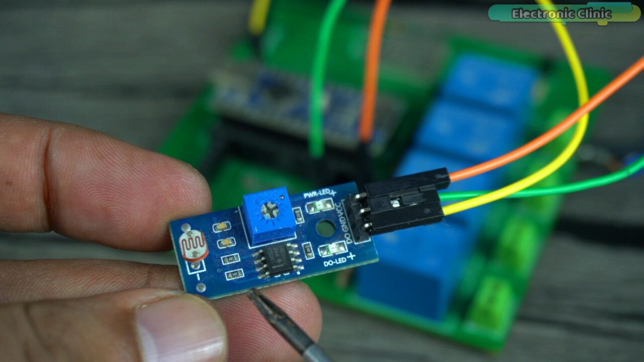
You know an LDR sensor is basically an analog sensor but this board is designed in a way that it gives 0 or 1 at the output when the light increases above or decreases below a set limit. So, this is a digital LDR sensor. And you can see this sensor board has a potentiometer which you can use to set the light sensitivity.
This sensor has a total of 3 pins which are clearly labeled with D0, GND, and VCC.
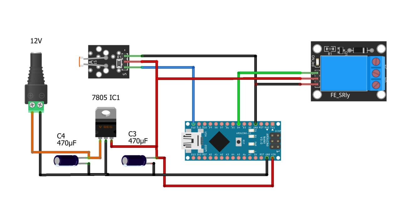
Connect D0 pin to the Arduino digital pin D12. Connect the VCC and GND pins to the Arduino 5V and GND pins.
A 5V SPDT type relay is connected to the Arduino pin D4. Now let’s go ahead and take a look at the programming.
Arduino LDR Sensor Programming:
|
1 2 3 4 5 6 7 8 9 10 11 12 13 14 15 16 17 18 19 20 21 22 23 24 25 |
int Sensor = 12; // Ldr Senosr int relay = 4; // 5v Relay Module void setup() { //Serial.begin(9600); pinMode (Sensor, INPUT); // LDR is an input device pinMode (relay, OUTPUT); // relay is an output device } void loop() { if(digitalRead(Sensor) == HIGH) // reads the digital signal, if light is not falling { digitalWrite(relay, HIGH); // turns on the light delay(3000); } if(digitalRead(Sensor) == LOW) // if light is falling on the LDR sensor { digitalWrite(relay, LOW); // turn off the light } } |
This program is just like the IR Digital Sensor program. Almost all the basic digital sensors work in the same exact way. We simply define the pins and then tell the controller which pins are going to be used as the input and which pins are going to be used as the output. Then we use the digitalRead() function to read the pin and then accordingly control the output. Instead of controlling the relay, we can add code for the GSM module to send a text message. Or you can turn on a Siren if incase you want to make a security system, or you can turn ON and turn OFF a DC or AC motor. It totally depends on you; how you decide to use it. Anyway, I have already uploaded this program and now let’s watch the Day and night Detection system in Action.

The 110/220Vac bulb is connected to the Relay and you can see the Arduino is powered up. When the 110/220Vac supply is connected never touch the relay contacts or copper traces on the top and bottom side of the PCB as it can be really dangerous. So, as far as possible wear protective gloves and as a beginner I would recommend to perform such high voltage experiments in front of someone having basic knowledge of the electricity rules and regulations. So, remember safety comes first.
For the demonstration purposes I am going to use my studio’s soft light as the sun. So, when the soft light is ON the bulb will remain OFF and when the soft light is turned off then the 110/220Vac bulb is going to turn ON.
As you can see the image above, the soft light is off that’s why the 110/220Vac bulb is ON.
If you replace this LDR sensor with a PIR motion sensor you can build yourself an automatic Corridor light controller or lawn light controller, or an automatic staircase light controller.
For the step by step explanation and practical demonstration watch the video tutorial given at the end of this article. Now, let’s move on to the next example.
Arduino Ultrasonic Sensor, Example 10:

In this 10th example, I am going to explain how to use the most popular HC-SR04 Ultrasonic Sensor with the Arduino and display the distance measurement value on the OLED display module. You can use an ultrasonic sensor for the obstacles detection in a robot, you can make a water level monitoring system, and you can even make a security system.
The HC-SR04 ultrasonic sensor uses sound waves to determine the distance between the sensor and an object. It emits an ultrasonic pulse and measures the time it takes for the pulse to bounce back after hitting an object. Since the speed of sound in air is relatively constant, you can calculate the distance by using the formula:
Distance = (Time × Speed of Sound) / 2
Where:
Time is the time it takes for the ultrasonic pulse to travel to the object and back.
Speed of Sound is the speed at which sound travels in air (approximately 343 meters per second at room temperature).
It has a total of four pins clearly labeled as Vcc, Trig, Echo,and Gnd.

Connect the Vcc and Gnd Pins to the Arduino 5V and GND pins. Connect the Trigger and Echo pins to the Arduino D10 and D9 respectively.
The SSD1306 Oled display module VCC and GND pins are connected to the Arduino 3.3V and GND pins. Whereas the SDA and SCL pins are connected to the Arduino A4 and A5 pins which are the I2C pins. A4 is the SDA and A5 is the SCL. I have already explained this in the Arduino Pinout. Now let’s go ahead and take a look at the programming.
Arduino Ultrasonic Sensor Programming:
|
1 2 3 4 5 6 7 8 9 10 11 12 13 14 15 16 17 18 19 20 21 22 23 24 25 26 27 28 29 30 31 32 33 34 35 36 37 38 39 40 41 42 43 44 45 46 47 48 49 50 51 52 53 54 55 56 |
#include <Adafruit_GFX.h> #include <Adafruit_SSD1306.h> const int trigPin = 10; const int echoPin = 9; // defines variables long duration; int distance; #define SCREEN_WIDTH 128 // OLED display width, in pixels #define SCREEN_HEIGHT 64 // OLED display height, in pixels // Declaration for an SSD1306 display connected to I2C (SDA, SCL pins) #define OLED_RESET -1 // Reset pin # (or -1 if sharing Arduino reset pin) Adafruit_SSD1306 display(SCREEN_WIDTH, SCREEN_HEIGHT, &Wire, OLED_RESET); void setup() { Serial.begin(9600); // Starts the serial communication pinMode(trigPin, OUTPUT); // Sets the trigPin as an Output pinMode(echoPin, INPUT); // Sets the echoPin as an Input display.begin(SSD1306_SWITCHCAPVCC, 0x3C); delay(2000); display.clearDisplay(); display.setTextColor(WHITE); delay(10); } void loop() { // Clears the trigPin digitalWrite(trigPin, LOW); delayMicroseconds(2); // Sets the trigPin on HIGH state for 10 micro seconds digitalWrite(trigPin, HIGH); delayMicroseconds(10); digitalWrite(trigPin, LOW); // Reads the echoPin, returns the sound wave travel time in microseconds duration = pulseIn(echoPin, HIGH); // Calculating the distance distance = duration * 0.034 / 2; // Prints the distance on the Serial Monitor Serial.print("Distance: "); Serial.println(distance); display.clearDisplay(); display.setTextSize(2); display.setCursor(0, 10); display.print("Distance"); display.setTextSize(3); display.setCursor(0, 35); display.print(distance); display.print("cm"); display.display(); } |
In the Oled display module example, I have already explained how to install these libraries. The Trigger and Echo pins of the Ultrasonic sensor are connected to the digital pins D10 and D9. Next, I defined two variables for storing the duration and distance values.
All these instructions are used with the Oled display module and I have already explained these. The trigger pin is set as output and the Echo pin is set as the input.
The trigPin is set to LOW to clear it to avoid any residual triggers.
A short 2-microsecond delay is added.
The trigPin is set to HIGH for 10 microseconds to trigger the ultrasonic pulse.
The trigPin is set back to LOW.
pulseIn() is used to measure the duration for which the echoPin remains HIGH, which corresponds to the time taken for the sound wave to travel to the object and back.
The distance is calculated using the formula and stored in the distance variable.
The calculated distance is printed to the Serial Monitor.
If you don’t want to print values on the serial monitor then you can deactivate the Serial communication and delete all these Serial.print() functions. I used it only for the debugging purposes just to confirm that everything is working. Anyway,
The OLED display is cleared.
Text size is set to 2, and “Distance” is printed at coordinates (0, 10) on the display.
Text size is set to 3, and the calculated distance is printed at coordinates (0, 35) on the display, along with the unit “cm”.
Finally, the display content is updated using the display.display() function.
Watch Video Tutorial:

Discover more from Electronic Clinic
Subscribe to get the latest posts sent to your email.


