Last Updated on September 21, 2024 by Engr. Shahzada Fahad
Table of Contents
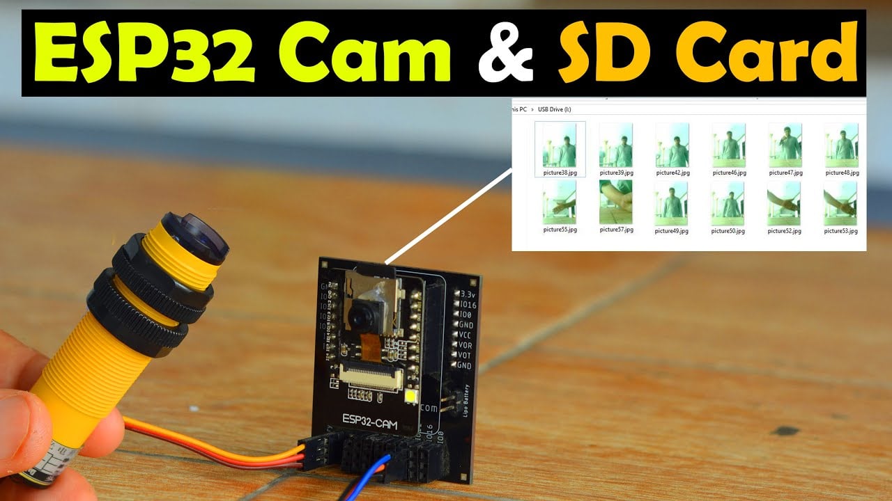
ESP32 Cam SD Card:
ESP32 Cam save Image to SD Card, IR Sensor with ESP32 Cam- I have already made many videos and have written several articles on ESP32 Cam. If you haven’t used the ESP32 camera module before, I highly recommend that you read my getting started article. Because in that article, I have discussed the issues related to ESP32 Camera Module. And I have also practically demonstrated; how to solve those issues.
In addition, I used the ESP32 Cam as a smart IoT Doorbell, in which I created a cell phone app with the help of the Blynk application; which I used for monitoring the camera and at the same time I used it to control the door lock.
I’ve also used the ESP32 Cam with Google Drive, and a lot of people liked this project. Because with the help of this project, you can monitor your camera from any corner of the world; provided if the internet connection is available.
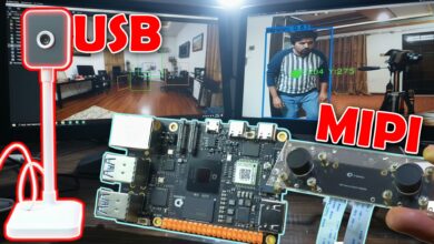
check my new project on ” ESP32 CAM and Python OpenCV Yolo V3 for object detection and identification”
For more ESP32 Cam-related videos visit my YouTube channel Electronic Clinic.
You may have noticed that there is a Micro-SD Card slot on the front of the ESP32 Cam module, by using which you can store images in it. And this way you can make a time lapse camera for yourself. I have already explained the time lapse camera function in the ESP32 Cam Google Drive project.
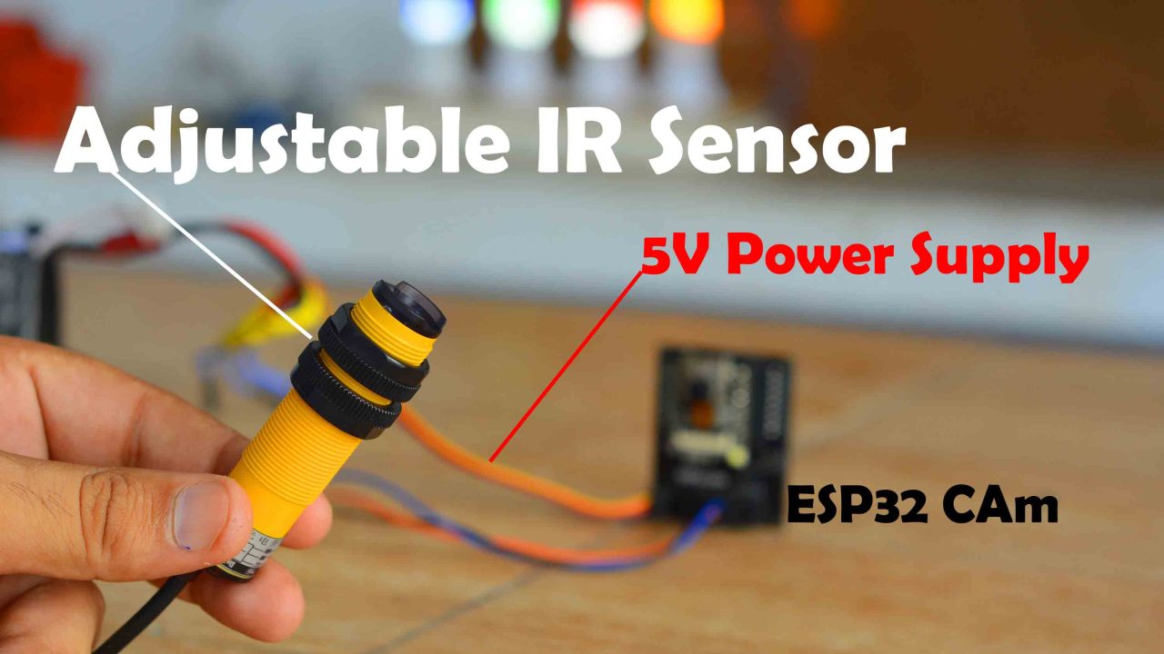
In today’s article, I will use this long-range adjustable IR sensor with the ESP32 Camera module. I have taken this IR sensor from DFRobot. I will share the complete specification of this IR sensor with you guys. Well, if you guys don’t have this IR sensor, you can use a simple push button for testing. I connected the IR Sensor with the ESP32 Camera module as per the circuit diagram which I will explain later in this article. First, I am going to explain its working and then I will start practical demonstration.
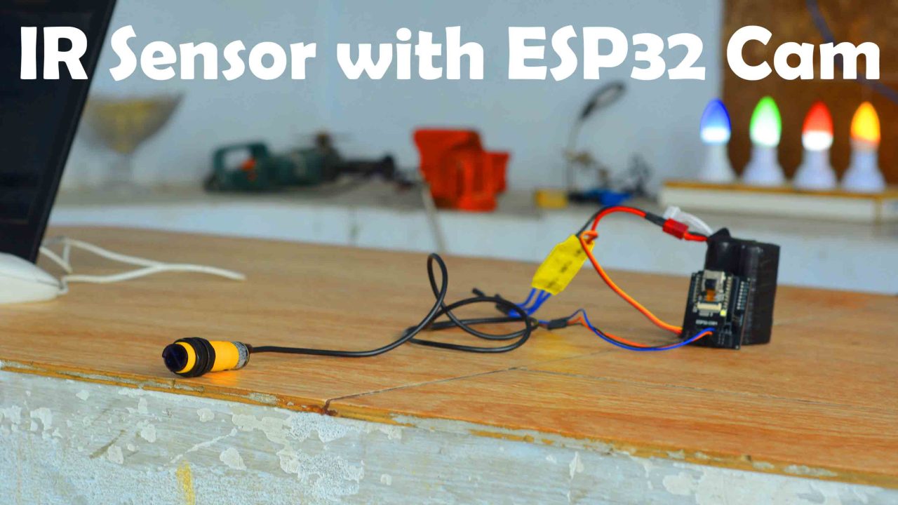
Before using the camera module, you have to insert the micro SD card into it. Then you have to install this IR sensor and camera at the place which you have to monitor. As you can see, there is quite a long cable with this IR sensor, so, you can easily install it at your desired location. For demonstration purposes, I will check this project on this table, so that all friends can easily understand it’s working.
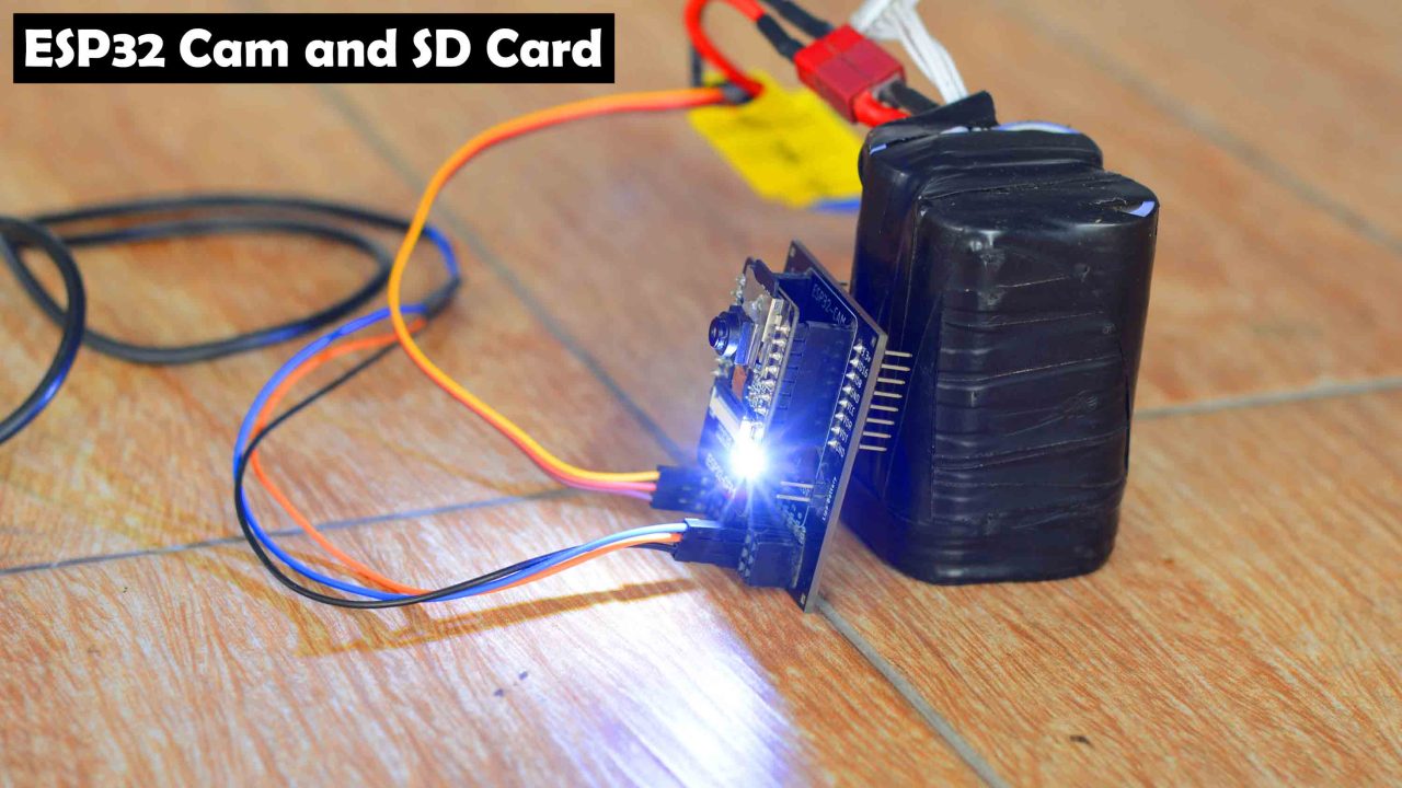
You can see I have powered up the ESP32 Camera module.
Now, if any object or person comes in the range of this IR sensor, ESP32 Cam will automatically capture its picture, and will save it in the SD card. So, let’s go ahead and start our practical demonstration.
I Placed the IR sensor on the front and ESP32 Camera module on the backside. And I adjusted the range as per the requirements.
For the initial testing, I waved my hand in front of the IR sensor and I could see flashes from the ESP32 Cam.
I did it two or three times and when I was satisfied. Then I told my cousin to walk in front of the IR Sensor.
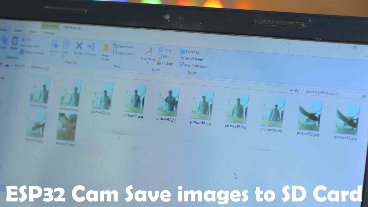
You can see the ESP32 Cam successfully captured all the images and saved them in the Micro SD card. I am sure by now, you might have got an idea of how does this system work. So, without any further delay let’s get started!!!
Amazon Links:
Arduino Nano USB C type (Recommended)
Disclosure: These are affiliate links. As an Amazon Associate I earn from qualifying purchases.
ESP32 CAM:
The ESP32-CAM is a small camera module with the ESP32-S chip that costs approximately $10. Besides the OV2640 camera, and several GPIOs to connect peripherals, it also features a microSD card slot that can be useful to store images taken with the camera or to store files to serve to clients.
ESP32-CAM ESP32 WIFI+Bluetooth Development Board Module w/ OV2640 Camera
Ultra-small 802.11b/g/n Wi-Fi + BT/BLE SoC module. Low-power dual-core 32-bit CPU for application processors.
Main frequency up to 240MHz, computing power up to 600 DMIPS.Built-in 520 KB SRAM, external 4M PSRAM.Supports interfaces such as UART/SPI/I2C/PWM/ADC/DAC.Support OV2640 and OV7670 cameras, built-in flash.

The ESP32-CAM is a small-sized camera module. The module can operate independently as a minimum system with a size of only 27*40.5*4.5mm and a deep sleep current of up to 6mA. It can be widely used in various IoT applications. It is an ideal solution for IoT applications.
Features:
- Ultra-small 802.11b/g/n Wi-Fi + BT/BLE SoC module.
- Low-power dual-core 32-bit CPU for application processors.
- Main frequency up to 240MHz, computing power up to 600 DMIPS.
- Built-in 520 KB SRAM, external 4M PSRAM.
- Supports interfaces such as UART/SPI/I2C/PWM/ADC/DAC.
- Support OV2640 and OV7670 cameras, built-in flash.
- Support image WiFi upload, support TF card.
- Support multiple sleep modes, embedded Lwip and FreeRTOS.
- Support STA/AP/STA+AP working mode.
- Support Smart Config/AirKiss one-click distribution network, support secondary development.
- It is suitable for home smart devices, industrial wireless control, wireless monitoring, QR wireless identification, wireless positioning system signals, and other applications.
- Packaged in DIP and can be directly plugged into the backplane for quick production.
Specifications:
- Material: Copper
- Module model: ESP32-CAM
- Package: DIP-16
- Size: 27*40.5*4.5(±0.2)mm
- SPI Flash: 32Mbit by default
- RAM: Internal 520KB + external 4M PSRAM
- BT: BT 4.2BR/EDR and BLE standards
- WiFi: 802.11 b/g/n/e/i
- Support interface: UARI, SPI, I2C, PWM
- Support TF card: maximum support 4G
- IO port: 9
- Serial port rate: default 115200bps
- Image output format: JPEG (only supported by OV2640), BMP, GRAYSCALE
- Spectrum range: 2412-2484MHz
- Antenna form: onboard antenna, gain 2dBi
- Security: WPA/WPA2/WPAS-Enterprise/WPS
- Power supply range: 5V
- Working temperature: -20 ° C -85 ° C
- Storage environment: -40°C-90°C, <90%RH
- Package size: 5*5*3cm/1.96*1.96*1.18in
- Package weight: 15g
Transmit power:
- 11 b: 17±2dBm (@11Mbps)
- 11 g: 14±2dBm (@54Mbps)
- 11 n: 13±2dBm (@MCS7)
Receive sensitivity:
- CCK, 1 Mbps: -90dBm
- CCK, 11 Mbps: -85dBm
- 6Mbps (1/2 BPSK): -88dBm
- 54Mbps (3/4 64-QAM): -70dBm
- MCS7 (65Mbps, 72.2Mbps): -67dBm
Power consumption:
- Turn off the flash: 180mA@5V
- Turn on the flash and adjust the brightness to the maximum: 310Ma@5V
- Deep-sleep: The lowest power consumption can reach 6mA@5V
- Modern-sleep: up to 20mA@5V
- Light-sleep: up to 6.7mA@5V
IR Adjustable Sensor:
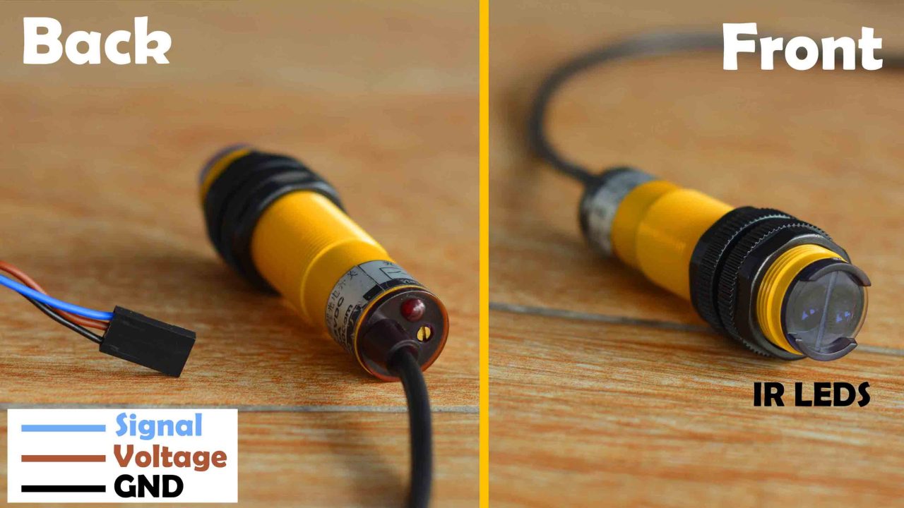
I have got this long-range Adjustable IR Sensor from DFRobot. On the front, it has got the transmitting and receiving IR LEDs. ON the back side you will find this Red color LED which lights up each time the sensor detects anything. Next, to the LED you can see this small screw, which you can use to adjust the detection range.
The Blue wire is the signal wire.
The Brown wire is the Voltage wire. And
The Black wire is the GND wire.
Specification:
The output form is PNP Normally Open.
The signal type is digital.
The operating voltage is 3V to 5volts. Due to such a wide input voltage range it can be used with all 3.3v and 5V compatible controller boards like ESP32 CAM, Arduino, ESP32, ESP8266, STM32, etc.
The detection range is from 0 to 200cm.
Interface is XH2.54-3Pin
Humidity: 35% to 95% RH
Switch Level: 0, No obstacles in the area; 1, there are obstacles in the area.
Storage Tempera is -25 to 75 degrees Celsius.
Operating temperature is -15 to +60 Degrees Celsius.
IR Sensor Applications:
Useful for robotics, interactive media, industrial assembly line, etc. Infrared wave length is part of the Sun’s natural light spectrum. While is a nice fit for indoor projects, outdoors with plenty of sun light and reflective surfaces on the sight is not advised. It’s incredibly repurposable and can be used for a lot of different projects. The adjustable screw on it’s back makes it very convenient for different purposes. Digital read on your Arduino pin and you are ready to go. Good sensor choice for quick prototyping.
IR Sensor Interfacing with ESP32 Cam:
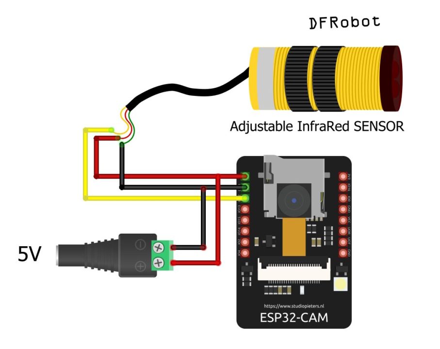
The circuit diagram is very simple. The signal wire of the IR Sensor is connected with the IO12 pin of the ESP32 Camera module.
ESP32 Cam Development Board:
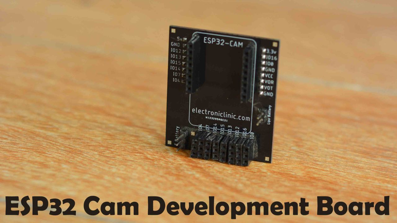
I have designed this simple development board for the ESP32 Camera module. You can see I have added these male and female headers for connecting the 5V power supply and for connecting different types of sensors. If you want to make the same development board, then you should watch my video on the ESP32 Cam development board.
ESP32 Cam Programming:
|
1 2 3 4 5 6 7 8 9 10 11 12 13 14 15 16 17 18 19 20 21 22 23 24 25 26 27 28 29 30 31 32 33 34 35 36 37 38 39 40 41 42 43 44 45 46 47 48 49 50 51 52 53 54 55 56 57 58 59 60 61 62 63 64 65 66 67 68 69 70 71 72 73 74 75 76 77 78 79 80 81 82 83 84 85 86 87 88 89 90 91 92 93 94 95 96 97 98 99 100 101 102 103 104 105 106 107 108 109 110 111 112 113 114 115 116 117 118 119 120 121 122 123 124 125 126 127 128 129 130 131 132 133 134 135 136 137 138 139 140 141 142 143 144 145 146 147 148 149 150 151 152 153 154 155 156 157 158 159 160 161 162 163 164 165 166 167 168 169 170 171 172 173 174 175 176 177 178 179 180 181 182 183 184 185 186 187 188 189 190 191 192 193 194 195 |
//========================================Including the libraries #include "esp_camera.h" //--> Camera ESP #include "Arduino.h" #include "FS.h" //--> SD Card ESP32 #include "SD_MMC.h" //--> SD Card ESP32 #include "SPI.h" #include "soc/soc.h" //--> Disable brownour problems #include "soc/rtc_cntl_reg.h" //--> Disable brownour problems #include "driver/rtc_io.h" #include <EEPROM.h> //--> read and write from flash memory //======================================== //========================================define the number of bytes you want to access #define EEPROM_SIZE 1 //======================================== //========================================Pin definition for CAMERA_MODEL_AI_THINKER #define PWDN_GPIO_NUM 32 #define RESET_GPIO_NUM -1 #define XCLK_GPIO_NUM 0 #define SIOD_GPIO_NUM 26 #define SIOC_GPIO_NUM 27 #define Y9_GPIO_NUM 35 #define Y8_GPIO_NUM 34 #define Y7_GPIO_NUM 39 #define Y6_GPIO_NUM 36 #define Y5_GPIO_NUM 21 #define Y4_GPIO_NUM 19 #define Y3_GPIO_NUM 18 #define Y2_GPIO_NUM 5 #define VSYNC_GPIO_NUM 25 #define HREF_GPIO_NUM 23 #define PCLK_GPIO_NUM 22 //======================================== int pictureNumber = 0; //--> Variable to hold photo naming sequence data from EEPROM. //________________________________________________________________________________void setup() void setup() { WRITE_PERI_REG(RTC_CNTL_BROWN_OUT_REG, 0); //--> disable brownout detector Serial.begin(115200); //Serial.setDebugOutput(true); //Serial.println(); //----------------------------------------Camera configuration camera_config_t config; config.ledc_channel = LEDC_CHANNEL_0; config.ledc_timer = LEDC_TIMER_0; config.pin_d0 = Y2_GPIO_NUM; config.pin_d1 = Y3_GPIO_NUM; config.pin_d2 = Y4_GPIO_NUM; config.pin_d3 = Y5_GPIO_NUM; config.pin_d4 = Y6_GPIO_NUM; config.pin_d5 = Y7_GPIO_NUM; config.pin_d6 = Y8_GPIO_NUM; config.pin_d7 = Y9_GPIO_NUM; config.pin_xclk = XCLK_GPIO_NUM; config.pin_pclk = PCLK_GPIO_NUM; config.pin_vsync = VSYNC_GPIO_NUM; config.pin_href = HREF_GPIO_NUM; config.pin_sscb_sda = SIOD_GPIO_NUM; config.pin_sscb_scl = SIOC_GPIO_NUM; config.pin_pwdn = PWDN_GPIO_NUM; config.pin_reset = RESET_GPIO_NUM; config.xclk_freq_hz = 20000000; config.pixel_format = PIXFORMAT_JPEG; if(psramFound()){ config.frame_size = FRAMESIZE_UXGA; // FRAMESIZE_ + QVGA|CIF|VGA|SVGA|XGA|SXGA|UXGA config.jpeg_quality = 10; config.fb_count = 2; } else { config.frame_size = FRAMESIZE_SVGA; config.jpeg_quality = 12; config.fb_count = 1; } //---------------------------------------- //----------------------------------------Init Camera esp_err_t err = esp_camera_init(&config); if (err != ESP_OK) { Serial.printf("Camera init failed with error 0x%x", err); return; } //---------------------------------------- //----------------------------------------Start accessing and checking SD card Serial.println("Starting SD Card"); delay(250); //******4-bit mode // Serial.println("Start accessing SD Card 4-bit mode"); // if(!SD_MMC.begin()){ // Serial.println("SD Card Mount Failed"); // return; // } // Serial.println("Started accessing SD Card 4-bit mode successfully"); //****** //******1-bit mode pinMode(13, INPUT_PULLUP); //--> This is done to resolve an "error" in 1-bit mode when SD_MMC.begin("/sdcard", true). Serial.println("Start accessing SD Card 1-bit mode"); if(!SD_MMC.begin("/sdcard", true)){ Serial.println("SD Card Mount Failed"); return; } Serial.println("Started accessing SD Card 1-bit mode successfully"); pinMode(13, INPUT_PULLDOWN); //****** //---------------------------------------- //----------------------------------------Checking SD card type uint8_t cardType = SD_MMC.cardType(); if(cardType == CARD_NONE){ Serial.println("No SD Card attached"); return; } //---------------------------------------- //----------------------------------------Turning on the LED Flash on the ESP32 Cam Board // The line of code to turn on the LED Flash is placed here, because the next line of code is the process of taking photos or pictures by the ESP32 Cam. pinMode(4, OUTPUT); digitalWrite(4, HIGH); delay(1000); //---------------------------------------- camera_fb_t * fb = NULL; //----------------------------------------Take Picture with Camera fb = esp_camera_fb_get(); if(!fb) { Serial.println("Camera capture failed"); return; } //---------------------------------------- digitalWrite(4, LOW); //--> Turn off the LED Flash because the process of taking pictures and saving images to the SD card is complete. delay(1000); //----------------------------------------initialize EEPROM with predefined size EEPROM.begin(EEPROM_SIZE); delay(50); pictureNumber = EEPROM.read(0) + 1; delay(50); //---------------------------------------- //----------------------------------------Save images to MicroSD Card. String path = "/picture" + String(pictureNumber) +".jpg"; //--> Path where new picture will be saved in SD Card fs::FS &fs = SD_MMC; Serial.printf("Picture file name: %s\n", path.c_str()); File file = fs.open(path.c_str(), FILE_WRITE); if(!file){ Serial.println("Failed to open file in writing mode"); } else { file.write(fb->buf, fb->len); // payload (image), payload length Serial.printf("Saved file to path: %s\n", path.c_str()); EEPROM.write(0, pictureNumber); EEPROM.commit(); } file.close(); //---------------------------------------- esp_camera_fb_return(fb); //--> return the frame buffer back to the driver for reuse. //----------------------------------------Go to "Sleep" mode. // The LED Flash will flash 2 times to indicate that it is in "Sleep" mode. Serial.println("Going to sleep now"); for(int i = 1; i <= 4; i++) { digitalWrite(4, !digitalRead(4)); delay(250); } esp_sleep_enable_ext0_wakeup(GPIO_NUM_12, 1); delay(500); //****** esp_deep_sleep_start(); Serial.println("This will never be printed"); //---------------------------------------- } void loop() { } |
Upload code into ESP32 Cam:
Uploading code into ESP32 Cam is a bit tricky. You will have to connect it to the Arduino to upload the code. You can follow these connections.
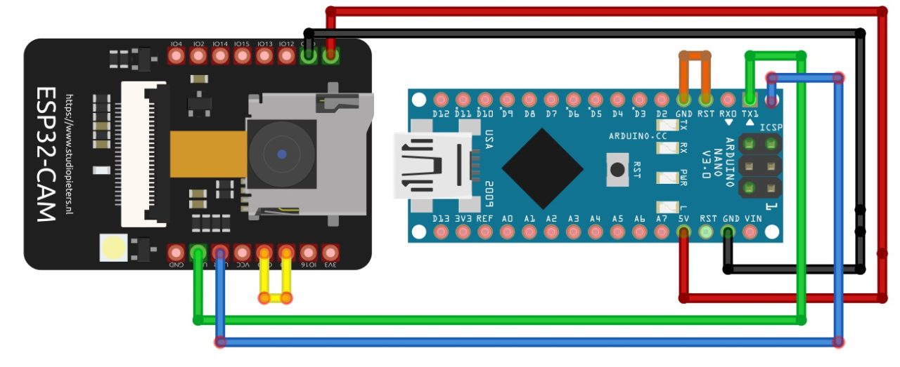
- Connect the 5V of the Arduino Nano with the 5V of the ESP32 CAM
- Connect the ground of the Arduino Nano with the ground of the ESP32 CAM
- Connect the TX pin of the Arduino Nano with the VOT of the ESP32 CAM
- Connect the RX pin of the Arduino Nano with the VOR of the ESP32 CAM
- Connect the reset pin with the ground in the Arduino Nano.
- Connect IOO of the ESP32 CAM with the Ground
Then we will select the following setting in the Arduino IDE.
- Board: ”ESP32 Wrover Module”
- Upload Speed: “115200”
- Flash Frequency: “80MHz”
- Flash Mode: “Q10” >
- Partition Scheme: “Huge APP (3MB No OTA/1 MB SPIFFS)” >
- Core Debug Level: “None” >
- Port: “COM port’ > According to your port connection
Upload the code to the ESP32 CAM:
Anyway, after uploading the code, I connected my IR sensor with the ESP32 CAM module. And I powered up the ESP32 Cam using a 5V regulated power supply.
Watch Video Tutorial
Discover more from Electronic Clinic
Subscribe to get the latest posts sent to your email.