ESP32 CAM Send Images to Google Drive, IoT Security Camera
Last Updated on September 21, 2024 by Engr. Shahzada Fahad
Table of Contents
ESP32 CAM Send Images to Google Drive:
ESP32 CAM Send Images to Google Drive, IoT Security Camera– ESP32 CAM is one of my favorite Camera Modules. I have been using the ESP32 CAM module in different projects. Previously I used it for controlling the Electronic Door lock using the Human Face recognition technique and I have also used the same ESP32 camera module for the live video streaming. These previously designed projects will really help you in getting started with the ESP32 Camera module.
If you are using the ESP32 CAM module for the first time, then you might face some issues. I myself, when I first started with the ESP32 Camera module, I had to deal with some errors including the Detected Camera not supported and the camera probe failed with error 0x20004. There is also another issue that you might face while working on the ESP32 Camera module and that is; the ESP32 Cam module keeps resetting automatically. So, if you face any of these issues then I highly recommend, you should read my getting started article on the ESP32 Cam.
You already know ESP32 Cam is an IoT-supported Camera module, which means you can connect this low-cost camera module with the WiFi Network, and this way you can build yourself an extremely powerful IoT Security Camera or surveillance system.
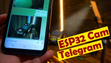
In this article, you will learn how to make an IoT Security Camera using the ESP32 Cam module and Google Drive. The ESP32 Cam captures the images and then sends them to Google drive. The images can be captured in two different ways.
- We can make it fully automatic by using a delay. So, the ESP32 Cam will capture the image after a fixed delay and then send it to Google drive. The delay time can be changed in the programming. So, let’s say if you want the ESP32 Camera to send an image after every 1 minute or let’s say 10 minutes, simply change the delay time in the code. Now, this technique can be quite useful in situations, where you need to monitor progress at a construction site or any other activity. So, this technique is useful when it comes to monitoring some kind of progress or activity. But, the same technique fails when the ESP32 CAM is used for security purposes. Because it seems quite impractical to send images at a regular time interval while there is no activity at all. So, that’s why I also created a 2nd version of the same project which I named as the IoT Security Camera.
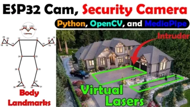
- Now, the 2nd version is also fully automatic but it captures and sends the images only when a sensor is activated. It can be any Analog or digital sensor. For demonstration purposes, I am going to use this IR Sensor. So, each time the IR Sensor is activated it will send an image to Google Drive. Let me practically show you both the techniques and then I will explain everything else.
check my new project on ” ESP32 CAM and Python OpenCV Yolo V3 for object detection and identification”

To get rid of the jumper wires, I designed these two PCB boards. If you want to use a 3.3V lipo battery or a 5V power supply then you can use only this board. This board also has these female headers which you can use to connect sensors and other electronic circuits. You can connect a 5V power supply over here or you can connect a 3.3V Lipo battery over here. The ESP32 Camera module nicely sits on the top of this circuit.
If you want to use a solar panel or any other voltage source which is between 9 and 25 volts then you can use the circuit which is on the left side. As you can see this board has the 7805 voltage regulator which accepts a wide range of input voltages and gives regulated 5 volts as the output which can be used to power up the ESP32 CAM and other sensors. So, if you are planning to control 12 volts relays then you should use this circuit. These circuits are provided with the male and female headers due to which these boards can be easily connected together without using the jumper wires.
Since in this project, I am not using any relays and 12 volts electronic devices, so, I am not going to use this circuit that has the 7805 voltage regulator.
ESP32 CAM Version1:
I have already uploaded the program which sends images to Google drive after every few seconds. Don’t worry, later in this article, I will explain how to upload a program.

My ESP32 CAM is absolutely ready and now it’s time to connect my 5V regulated power supply. When the LED flashes it means the ESP32 CAM has connected with the WiFi network.

You can see I received many images in my Google drive from the ESP32 CAM. This is version1 and its job is to send images to Google drive after every few seconds. As I explained earlier this type of project can be quite useful in situations where you need to monitor a specific type of activity or work progress, etc. Since the images are uploaded to Google drive it means you can monitor any specific activity from anywhere in the world.
You might know, every Google account comes with 15GB of storage that’s shared across Google Drive, Gmail, and Google Photos. So, make sure you don’t use short delays otherwise in a day or so your entire Google Drive will be filled with images.
You can see I have already received many images from the ESP32 Cam and if I didn’t stop the ESP32 Cam it will keep sending the images to my Google Drive. So, I powered off my ESP32 CAM and I also deleted all the images. Now, let’s watch the 2nd version of the same project in action.
ESP32 CAM Version2:

This time I connected this IR Sensor with the ESP32 CAM. If you want you can use a PIR sensor or a Microwave sensor or an ultrasonic sensor or any other sensor as per your requirement. Anyways, now the ESP32 CAM will only send images when the IR sensor is activated. ON the IR sensor both the LEDs are ON which means there is nothing in front of the sensor, so the ESP32 CAM will not send any image to the Google drive.

When I placed my hand in front of the IR Sensor, it successfully detected my hand and sent an image to the Google Drive. You can see the ESP32 CAM only send an image to Google Drive when the IR Sensor is activated. This is how easily you can convert your ESP32 CAM into an IoT Security Camera. Now, you have got an idea of what exactly you are going to learn after watching this video. So, without any further delay, let’s get started!!!
Amazon Links:
Arduino Nano USB C type (Recommended)
Disclosure: These are affiliate links. As an Amazon Associate I earn from qualifying purchases.
ESP32 CAM:
ESP32-CAM can be widely used in various IoT applications. It is suitable for home smart devices, industrial wireless control, wireless monitoring, QR wireless identification, wireless positioning system signals and other IoT applications. It is an ideal solution for IoT applications.

Parameters:
- Working voltage: 4.75-5.25V
- SPIFlash: Default 32Mbit
- RAM: Internal 520KB + external 8MB PSRAM
- Wi-Fi: 802.11b/g/n/e/i
- Bluetooth: Bluetooth 4.2BR/EDR and BLE standard
- Support interface (2Mbps): UART, SPI, I2C, PWM
- Support TF card: maximum support 4G
- IO port: 9
- Serial port rate: default 115200bps
- Spectrum range: 2400 ~2483.5MHz
- Antenna form: onboard PCB antenna, gain 2dBi
- Image output format: JPEG (only OV2640 support), BMP, GRAYSCALE
Features:
- Using low-power dual-core 32-bit CPU, which can be used as an application processor.
- The main frequency is up to 240MHz, and the computing power is up to 600 DMIPS
- Built-in 520 KB SRAM, external 8MB PSRAM
- Support UART/SPI/I2C/PWM/ADC/DAC and other interfaces
- Support OV2640 and OV7670 cameras, built-in flash
- Support picture WiFI upload
- Support multiple sleep modes.
- Lwip and FreeRTOS embedded
- Support STA/AP/STA+AP working mode
- Support Smart Config/AirKiss one-click network configuration
- Support secondary development
ESP32 Camera Module development board Top Circuit:

This is the circuit diagram of the top PCB board. As you can see there is nothing complicated. Male and female Headers are connected with the Power Supply and I/O pins of the ESP32 Camera Module. The SV3 and SV4 male headers are used to make connection with the bottom circuit board. The JP1 is used to connect a 3.3V Lipo battery while the JP2 is used to connect the 5V regulated power supply. All the other headers are used for interfacing Sensors and other output devices.
ESP32 Camera Module Development board Bottom Circuit:

This is the circuit diagram of the bottom PCB board. Female headers are connected with the Power Supply and I/O pins of the ESP32 Camera Module. The bottom PCB board is provided with the 5V regulated power supply based on the linear voltage regulator LM7805. A voltage source greater than 6V and less than 28 Volts is connected with the DC female power jack J1. This way the ESP32 Camera Module can also be powered up using a solar panel, 12V battery, or a 12V adaptor, etc. I also added headers for the 12V and GND connections, if in case you want to control 12V relays, small 12V dc motors, etc.
I used Cadesoft Eagle for designing the Top and Bottom PCBs. I have already explained The PCB designing and soldering in my previous article based on the Face recognition door lock control system.
ESP32 CAM Send image to Google Driver Code:
The project code consists of three files.
espcam.ino
Base64.cpp
Base64.h
espcam code:
|
1 2 3 4 5 6 7 8 9 10 11 12 13 14 15 16 17 18 19 20 21 22 23 24 25 26 27 28 29 30 31 32 33 34 35 36 37 38 39 40 41 42 43 44 45 46 47 48 49 50 51 52 53 54 55 56 57 58 59 60 61 62 63 64 65 66 67 68 69 70 71 72 73 74 75 76 77 78 79 80 81 82 83 84 85 86 87 88 89 90 91 92 93 94 95 96 97 98 99 100 101 102 103 104 105 106 107 108 109 110 111 112 113 114 115 116 117 118 119 120 121 122 123 124 125 126 127 128 129 130 131 132 133 134 135 136 137 138 139 140 141 142 143 144 145 146 147 148 149 150 151 152 153 154 155 156 157 158 159 160 161 162 163 164 165 166 167 168 169 170 171 172 173 174 175 176 177 178 179 180 181 182 183 184 185 186 187 188 189 190 191 192 193 194 195 196 197 198 199 200 201 202 203 204 205 206 207 208 209 210 211 212 213 214 215 216 217 218 219 220 221 222 223 224 225 226 227 228 229 230 231 232 233 234 235 236 237 238 239 240 241 242 243 244 245 246 247 248 249 250 251 252 253 254 255 |
// Enter your WiFi ssid and password const char* ssid = "AndroidAP3DEC"; //your network SSID const char* password = "engrhammad"; //your network password String myScript = "/macros/s/AKfycbxcnqrIeZjKohDYYwADWckLugt1Mr_sh-lAEcWw7TScxDNLexU/exec"; //Create your Google Apps Script and replace the "myScript" path. String myLineNotifyToken = "myToken=**********"; //Line Notify Token. You can set the value of xxxxxxxxxx empty if you don't want to send picture to Linenotify. String myFoldername = "&myFoldername=ESP32-CAM"; String myFilename = "&myFilename=ESP32-CAM.jpg"; String myImage = "&myFile="; #include <WiFi.h> #include <WiFiClientSecure.h> #include "soc/soc.h" #include "soc/rtc_cntl_reg.h" #include "Base64.h" #include "esp_camera.h" // WARNING!!! Make sure that you have either selected ESP32 Wrover Module, // or another board which has PSRAM enabled //CAMERA_MODEL_AI_THINKER #define PWDN_GPIO_NUM 32 #define RESET_GPIO_NUM -1 #define XCLK_GPIO_NUM 0 #define SIOD_GPIO_NUM 26 #define SIOC_GPIO_NUM 27 #define Y9_GPIO_NUM 35 #define Y8_GPIO_NUM 34 #define Y7_GPIO_NUM 39 #define Y6_GPIO_NUM 36 #define Y5_GPIO_NUM 21 #define Y4_GPIO_NUM 19 #define Y3_GPIO_NUM 18 #define Y2_GPIO_NUM 5 #define VSYNC_GPIO_NUM 25 #define HREF_GPIO_NUM 23 #define PCLK_GPIO_NUM 22 void setup() { WRITE_PERI_REG(RTC_CNTL_BROWN_OUT_REG, 0); Serial.begin(115200); delay(10); WiFi.mode(WIFI_STA); Serial.println(""); Serial.print("Connecting to "); Serial.println(ssid); WiFi.begin(ssid, password); long int StartTime=millis(); while (WiFi.status() != WL_CONNECTED) { delay(500); if ((StartTime+10000) < millis()) break; } Serial.println(""); Serial.println("STAIP address: "); Serial.println(WiFi.localIP()); Serial.println(""); if (WiFi.status() != WL_CONNECTED) { Serial.println("Reset"); ledcAttachPin(4, 3); ledcSetup(3, 5000, 8); ledcWrite(3,10); delay(200); ledcWrite(3,0); delay(200); ledcDetachPin(3); delay(1000); ESP.restart(); } else { ledcAttachPin(4, 3); ledcSetup(3, 5000, 8); for (int i=0;i<5;i++) { ledcWrite(3,10); delay(200); ledcWrite(3,0); delay(200); } ledcDetachPin(3); } camera_config_t config; config.ledc_channel = LEDC_CHANNEL_0; config.ledc_timer = LEDC_TIMER_0; config.pin_d0 = Y2_GPIO_NUM; config.pin_d1 = Y3_GPIO_NUM; config.pin_d2 = Y4_GPIO_NUM; config.pin_d3 = Y5_GPIO_NUM; config.pin_d4 = Y6_GPIO_NUM; config.pin_d5 = Y7_GPIO_NUM; config.pin_d6 = Y8_GPIO_NUM; config.pin_d7 = Y9_GPIO_NUM; config.pin_xclk = XCLK_GPIO_NUM; config.pin_pclk = PCLK_GPIO_NUM; config.pin_vsync = VSYNC_GPIO_NUM; config.pin_href = HREF_GPIO_NUM; config.pin_sscb_sda = SIOD_GPIO_NUM; config.pin_sscb_scl = SIOC_GPIO_NUM; config.pin_pwdn = PWDN_GPIO_NUM; config.pin_reset = RESET_GPIO_NUM; config.xclk_freq_hz = 20000000; config.pixel_format = PIXFORMAT_JPEG; //init with high specs to pre-allocate larger buffers if(psramFound()){ config.frame_size = FRAMESIZE_UXGA; config.jpeg_quality = 10; //0-63 lower number means higher quality config.fb_count = 2; } else { config.frame_size = FRAMESIZE_SVGA; config.jpeg_quality = 12; //0-63 lower number means higher quality config.fb_count = 1; } // camera init esp_err_t err = esp_camera_init(&config); if (err != ESP_OK) { Serial.printf("Camera init failed with error 0x%x", err); delay(1000); ESP.restart(); } //drop down frame size for higher initial frame rate sensor_t * s = esp_camera_sensor_get(); s->set_framesize(s, FRAMESIZE_VGA); // UXGA|SXGA|XGA|SVGA|VGA|CIF|QVGA|HQVGA|QQVGA } void loop() { SendCapturedImage(); delay(60000); } String SendCapturedImage() { const char* myDomain = "script.google.com"; String getAll="", getBody = ""; camera_fb_t * fb = NULL; fb = esp_camera_fb_get(); if(!fb) { Serial.println("Camera capture failed"); delay(1000); ESP.restart(); return "Camera capture failed"; } Serial.println("Connect to " + String(myDomain)); WiFiClientSecure client_tcp; client_tcp.setInsecure(); //run version 1.0.5 or above if (client_tcp.connect(myDomain, 443)) { Serial.println("Connection successful"); char *input = (char *)fb->buf; char output[base64_enc_len(3)]; String imageFile = "data:image/jpeg;base64,"; for (int i=0;i<fb->len;i++) { base64_encode(output, (input++), 3); if (i%3==0) imageFile += urlencode(String(output)); } String Data = myLineNotifyToken+myFoldername+myFilename+myImage; client_tcp.println("POST " + myScript + " HTTP/1.1"); client_tcp.println("Host: " + String(myDomain)); client_tcp.println("Content-Length: " + String(Data.length()+imageFile.length())); client_tcp.println("Content-Type: application/x-www-form-urlencoded"); client_tcp.println("Connection: keep-alive"); client_tcp.println(); client_tcp.print(Data); int Index; for (Index = 0; Index < imageFile.length(); Index = Index+1000) { client_tcp.print(imageFile.substring(Index, Index+1000)); } esp_camera_fb_return(fb); int waitTime = 10000; // timeout 10 seconds long startTime = millis(); boolean state = false; while ((startTime + waitTime) > millis()) { Serial.print("."); delay(100); while (client_tcp.available()) { char c = client_tcp.read(); if (state==true) getBody += String(c); if (c == '\n') { if (getAll.length()==0) state=true; getAll = ""; } else if (c != '\r') getAll += String(c); startTime = millis(); } if (getBody.length()>0) break; } client_tcp.stop(); Serial.println(getBody); } else { getBody="Connected to " + String(myDomain) + " failed."; Serial.println("Connected to " + String(myDomain) + " failed."); } return getBody; } String urlencode(String str) { String encodedString=""; char c; char code0; char code1; char code2; for (int i =0; i < str.length(); i++){ c=str.charAt(i); if (c == ' '){ encodedString+= '+'; } else if (isalnum(c)){ encodedString+=c; } else{ code1=(c & 0xf)+'0'; if ((c & 0xf) >9){ code1=(c & 0xf) - 10 + 'A'; } c=(c>>4)&0xf; code0=c+'0'; if (c > 9){ code0=c - 10 + 'A'; } code2='\0'; encodedString+='%'; encodedString+=code0; encodedString+=code1; //encodedString+=code2; } yield(); } return encodedString; } |
Base64.cpp
|
1 2 3 4 5 6 7 8 9 10 11 12 13 14 15 16 17 18 19 20 21 22 23 24 25 26 27 28 29 30 31 32 33 34 35 36 37 38 39 40 41 42 43 44 45 46 47 48 49 50 51 52 53 54 55 56 57 58 59 60 61 62 63 64 65 66 67 68 69 70 71 72 73 74 75 76 77 78 79 80 81 82 83 84 85 86 87 88 89 90 91 92 93 94 95 96 97 98 99 100 101 102 103 104 105 106 107 108 109 110 111 112 113 114 115 116 117 118 119 120 121 122 123 124 125 126 127 128 129 130 131 132 133 134 135 136 137 138 139 140 |
/* * Copyright (c) 2013 Adam Rudd. * See LICENSE for more information * https://github.com/adamvr/arduino-base64 */ #if (defined(__AVR__)) #include <avr\pgmspace.h> #else #include <pgmspace.h> #endif const char PROGMEM b64_alphabet[] = "ABCDEFGHIJKLMNOPQRSTUVWXYZ" "abcdefghijklmnopqrstuvwxyz" "0123456789+/"; /* 'Private' declarations */ inline void a3_to_a4(unsigned char * a4, unsigned char * a3); inline void a4_to_a3(unsigned char * a3, unsigned char * a4); inline unsigned char b64_lookup(char c); int base64_encode(char *output, char *input, int inputLen) { int i = 0, j = 0; int encLen = 0; unsigned char a3[3]; unsigned char a4[4]; while(inputLen--) { a3[i++] = *(input++); if(i == 3) { a3_to_a4(a4, a3); for(i = 0; i < 4; i++) { output[encLen++] = pgm_read_byte(&b64_alphabet[a4[i]]); } i = 0; } } if(i) { for(j = i; j < 3; j++) { a3[j] = '\0'; } a3_to_a4(a4, a3); for(j = 0; j < i + 1; j++) { output[encLen++] = pgm_read_byte(&b64_alphabet[a4[j]]); } while((i++ < 3)) { output[encLen++] = '='; } } output[encLen] = '\0'; return encLen; } int base64_decode(char * output, char * input, int inputLen) { int i = 0, j = 0; int decLen = 0; unsigned char a3[3]; unsigned char a4[4]; while (inputLen--) { if(*input == '=') { break; } a4[i++] = *(input++); if (i == 4) { for (i = 0; i <4; i++) { a4[i] = b64_lookup(a4[i]); } a4_to_a3(a3,a4); for (i = 0; i < 3; i++) { output[decLen++] = a3[i]; } i = 0; } } if (i) { for (j = i; j < 4; j++) { a4[j] = '\0'; } for (j = 0; j <4; j++) { a4[j] = b64_lookup(a4[j]); } a4_to_a3(a3,a4); for (j = 0; j < i - 1; j++) { output[decLen++] = a3[j]; } } output[decLen] = '\0'; return decLen; } int base64_enc_len(int plainLen) { int n = plainLen; return (n + 2 - ((n + 2) % 3)) / 3 * 4; } int base64_dec_len(char * input, int inputLen) { int i = 0; int numEq = 0; for(i = inputLen - 1; input[i] == '='; i--) { numEq++; } return ((6 * inputLen) / 8) - numEq; } inline void a3_to_a4(unsigned char * a4, unsigned char * a3) { a4[0] = (a3[0] & 0xfc) >> 2; a4[1] = ((a3[0] & 0x03) << 4) + ((a3[1] & 0xf0) >> 4); a4[2] = ((a3[1] & 0x0f) << 2) + ((a3[2] & 0xc0) >> 6); a4[3] = (a3[2] & 0x3f); } inline void a4_to_a3(unsigned char * a3, unsigned char * a4) { a3[0] = (a4[0] << 2) + ((a4[1] & 0x30) >> 4); a3[1] = ((a4[1] & 0xf) << 4) + ((a4[2] & 0x3c) >> 2); a3[2] = ((a4[2] & 0x3) << 6) + a4[3]; } inline unsigned char b64_lookup(char c) { if(c >='A' && c <='Z') return c - 'A'; if(c >='a' && c <='z') return c - 71; if(c >='0' && c <='9') return c + 4; if(c == '+') return 62; if(c == '/') return 63; return -1; } |
Base64.h
|
1 2 3 4 5 6 7 8 9 10 11 12 13 14 15 16 17 18 19 20 21 22 23 24 25 26 27 28 29 30 31 32 33 34 35 36 37 38 39 40 41 42 43 44 45 46 47 48 49 50 51 52 53 54 55 56 57 58 59 60 61 62 63 64 65 66 67 68 69 70 71 72 73 74 75 76 77 78 79 80 |
/* * Copyright (c) 2013 Adam Rudd. * See LICENSE for more information * https://github.com/adamvr/arduino-base64 */ #ifndef _BASE64_H #define _BASE64_H /* b64_alphabet: * Description: Base64 alphabet table, a mapping between integers * and base64 digits * Notes: This is an extern here but is defined in Base64.c */ extern const char b64_alphabet[]; /* base64_encode: * Description: * Encode a string of characters as base64 * Parameters: * output: the output buffer for the encoding, stores the encoded string * input: the input buffer for the encoding, stores the binary to be encoded * inputLen: the length of the input buffer, in bytes * Return value: * Returns the length of the encoded string * Requirements: * 1. output must not be null or empty * 2. input must not be null * 3. inputLen must be greater than or equal to 0 */ int base64_encode(char *output, char *input, int inputLen); /* base64_decode: * Description: * Decode a base64 encoded string into bytes * Parameters: * output: the output buffer for the decoding, * stores the decoded binary * input: the input buffer for the decoding, * stores the base64 string to be decoded * inputLen: the length of the input buffer, in bytes * Return value: * Returns the length of the decoded string * Requirements: * 1. output must not be null or empty * 2. input must not be null * 3. inputLen must be greater than or equal to 0 */ int base64_decode(char *output, char *input, int inputLen); /* base64_enc_len: * Description: * Returns the length of a base64 encoded string whose decoded * form is inputLen bytes long * Parameters: * inputLen: the length of the decoded string * Return value: * The length of a base64 encoded string whose decoded form * is inputLen bytes long * Requirements: * None */ int base64_enc_len(int inputLen); /* base64_dec_len: * Description: * Returns the length of the decoded form of a * base64 encoded string * Parameters: * input: the base64 encoded string to be measured * inputLen: the length of the base64 encoded string * Return value: * Returns the length of the decoded form of a * base64 encoded string * Requirements: * 1. input must not be null * 2. input must be greater than or equal to zero */ int base64_dec_len(char *input, int inputLen); #endif // _BASE64_H |
The espcam.ino is the main code which sends images to Google Drive at regular intervals. There are a few things which I would like to explain. Before, you start the programming, first of all, make sure you install the ESP32 board manager URL link and for this, you can watch my getting started tutorial on the ESP32 module. Once you have installed the board then you should be able to see the ESP32 Wrover Module.
ESPCAM is the main code, which consists of the SSID, Password, and the Google Apps Script path which I will explain in a minute. Now, if we go to the main loop() function.
|
1 2 3 4 5 |
void loop() { SendCapturedImage(); delay(60000); } |
You can see inside this loop() function we have only one function the SendCapturedImage() and then a delay. You can increase or decrease this delay. Personally, I don’t like delays inside the main loop() function, because it really disturbs the normal execution of the program, because once the control enters into the delay function then it stays there and the controller won’t do anything until the delay is over. So, apart from sending the images to Google Driver, if you also want to monitor some sensors then I highly recommend don’t use a delay, you can use a timer.
This code is ready to use means you don’t need to change anything except the delay, SSID, Password, and the Google Apps Script path. The espcam, Base64.cpp and Base64.h files are need to be inside the same folder.
Download Complete project code:
Once download the project code then you will need the Google apps script path.
Google Apps script application:
First of all, we will create the Google script application in which we will receive the image from the ESP32 CAM. So we will open the Google script and click on the Start Scripting.

Then we will click on the New project.

After that we will give a name to the project ESP_CAM by renaming the Untitled project.

After that we will upload the following code in the code section and click on the save button.
Google Script code:
|
1 2 3 4 5 6 7 8 9 10 11 12 13 14 15 16 17 18 19 20 21 22 23 24 25 26 27 28 29 30 31 32 33 34 35 36 37 38 39 40 41 42 43 44 45 |
function doPost(e) { var myFoldername = e.parameter.myFoldername; var myFile = e.parameter.myFile; var myFilename = e.parameter.myFilename; //var myFilename = Utilities.formatDate(new Date(), "GMT", "yyyyMMddHHmmss")+"-"+e.parameter.myFilename; var myToken = e.parameter.myToken; var contentType = myFile.substring(myFile.indexOf(":")+1, myFile.indexOf(";")); var data = myFile.substring(myFile.indexOf(",")+1); data = Utilities.base64Decode(data); var blob = Utilities.newBlob(data, contentType, myFilename); // Save a captured image to Google Drive. var folder, folders = DriveApp.getFoldersByName(myFoldername); if (folders.hasNext()) { folder = folders.next(); } else { folder = DriveApp.createFolder(myFoldername); } var file = folder.createFile(blob); file.setDescription("Uploaded by " + myFilename); var imageID = file.getUrl().substring(file.getUrl().indexOf("/d/")+3,file.getUrl().indexOf("view")-1); var imageUrl = "https://drive.google.com/uc?authuser=0&id="+imageID; // Send a link message to Line Notify. var res = "Line Notify: "; try { var url = 'https://notify-api.line.me/api/notify'; var response = UrlFetchApp.fetch(url, { 'headers': { 'Authorization': 'Bearer ' + myToken, }, 'method': 'post', 'payload': { 'message': imageUrl } }); res += response.getContentText(); } catch(error) { res += error; } return ContentService.createTextOutput(myFoldername+"/"+myFilename+"\n"+imageUrl+"\n"+res); } |
Now, click on the Publish Menu and then click on the Deploy as web app…

Then a dialog box will appear in which you will be asked “Select who has access to the App” you have to select anyone, even anonymous.

Click on the Deploy button a dialog box will appear in which we will click on the Review Permission.

After that we will select the account in which we have created the Google Apps script
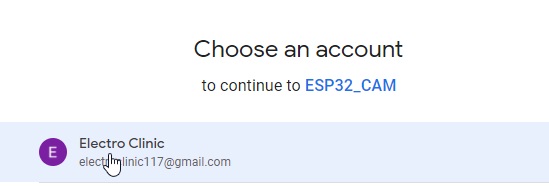
Then click on the advance and click on the Go to the ESP32_CAM (unsafe).

After that click on the Allow button.

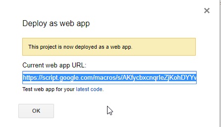
Then the Google Apps Script URL will appear which we will use in our code, copy that URL and paste in the browser.
After this copy the selected code.

Now open the code in the Arduino ide and paste the code.

Uploading the code to the ESP32 CAM:
Now, you have two ways to upload the program. You can use a USB to TTL converter or you can use an Arduino board to upload the program. Since most of the beginners don’t have USB to TTL converter, so, I will use Arduino with the ESP32 Cam to upload the program. Let’s take a look at the connections diagram.
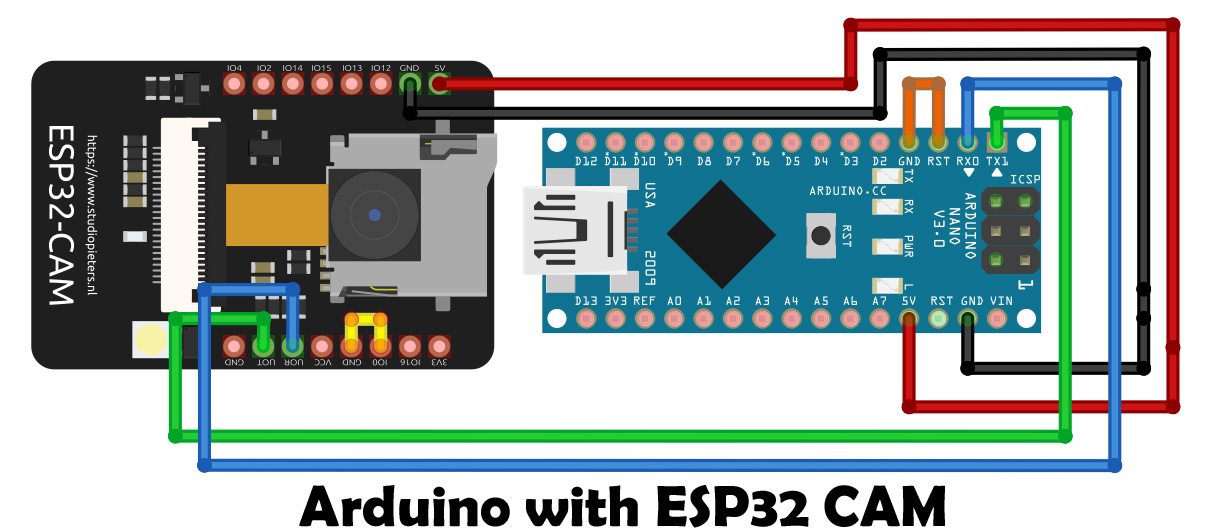
- Connect the 5V of the Arduino Nano with the 5V of the ESP32 CAM
- Connect the ground of the Arduino Nano with the ground of the ESP32 CAM
- Connect the TX pin of the Arduino Nano with the VOT of the ESP32 CAM
- Connect the RX pin of the Arduino Nano with the VOR of the ESP32 CAM
- Connect the reset pin with the ground in the Arduino Nano.
- Connect IOO of the ESP32 CAM with the Ground
Then we will select the following setting in the Arduino IDE.
- Board: ”ESP32 Wrover Module”
- Upload Speed: “115200”
- Flash Frequency: “40MHz”
- Flash Mode: “Q10” >
- Partition Scheme: “Huge APP (3MB No OTA/1 MB SPIFFS)” >
- Core Debug Level: “None” >
- Port: “COM port’ > According to your port connection

After doing all these settings, then you can click on the upload button.
After uploading the code, remove the wire which shorts the IO0 and ground pins of the ESP32 CAM.

Now, the ESP32 CAM is completely ready. You can use 5V and GND from the Arduino to power up the ESP32 CAM which is good for the initial testing, but in the long run, it seems quite impractical to use Arduino to power up the ESP32 CAM.

I highly recommend you should get a board like this. So, if you want to make the same ESP32 CAM development board? Then you can download the PCB design files which I have already shared above. My ESP32 CAM is absolutely ready and now it’s time to connect my 5V regulated power supply.
You can see I received many images in my Google drive from the ESP32 CAM. This is version1 and its job is to send images to Google drive after every few seconds. Now, let’s take a look at the circuit diagram of version2 which is the IoT Security Camera.
ESP32 IoT Security Camera Circuit Diagram:

The VCC and GND pins of the IR sensor are connected with the 3.3V and GND pins of the ESP32 CAM. The OUT pin of the IR sensor is connected with the IO13 pin of the ESP32 Camera module.
I connected my IR Obstacle sensor module with the ESP32 CAM as per the circuit diagram and now, let’s take a look at the ESP32 CAM based IoT Security Camera code.

Download esp32 cam ir sensor code
This is the same exact program, I didn’t change anything except adding this if condition. Now the ESP32 Cam will only send images to the Google drive when the IR Sensor is activated. I have already uploaded the program using the same method as previously explained. Now, Let’s watch the ESP32 CAM based IoT Security Camera in Action.
When the IR sensor senses any obstacle.
If you face any issues then you can watch my video tutorial given below.
Watch Video Tutorial:

Discover more from Electronic Clinic
Subscribe to get the latest posts sent to your email.
Hi, great project!
I am trying too to put captured images on google drive, but I struggle a bit.
Sometimes the images are correctly uploaded but mostly I get the response that connection with google drive failed. Since it sometimes works, everything should be correctly set up. I have no problem with my wifi connection. When I try the sample cam webserver it works like a charm. Any suggestion what I can check?
Thanks for the great tutorial, really helped me getting started!
Somehow the images I take come with a weird effect: at the top of the image there is always a dark overlay over the image and below that the images comes out way too bright, see this example: https://drive.google.com/file/d/1PdUQlJJ1OAMZzaFWXV12h70SvVQIvcO6/view?usp=drivesdk
I tested again with your code as-is just changing my network and google drive credentials, always the same result. Maybe you or anyone else can help solve this issue;
1. What could cause this?
2. How can I solve it?
Thanks if anyone has an idea,
Jan
After playing around a bit more I noticed that pictures taken in a later loop iteration do not show this error. So I assume the camera is simply not ready right after boot up of esp32 module. Around 30-60 seconds after boot up, images turn out good.
Is there a way/function to check if the camera is fully ready to use? Right now I’m just guessing with a 60sec delay that it should be ready.
I am also using your code in a different sketch where I implemented DHT22 temp/humidity measurement, OTA and some other things. Strangely here the 60 seconds are not enough. Some images don’t even turn out good after a delay of 2-3 minutes.
Any idea how to solve this?
The latest esp32 release, 3.0 has changed the LEDC API.
This causes error messages during compilation like: ‘ledcAttachPin’ was not declared in this scope; did you mean ‘ledcAttach’?
But the API is only used in the ‘if’ and the ‘else’ statements following the WiFi connection check, apparently to blink the LED to confirm connection.
Rather than figure our the new syntax I just commented out the relevant lines, and everything worked fine.
Nice little program. I am using it to take a daily picture of my gas meter.
I can enhance the google script to use OCR to extract the numbers.
Many Thanks!