ESP32 Cam: ESP32 Camera Programming using Arduino, Issues Fixed
Last Updated on August 25, 2024 by Engr. Shahzada Fahad
Table of Contents
ESP32 Cam Programming using Arduino, Description:
In this tutorial, you will learn how to program the ESP32 Cam using Arduino Uno or Arduino Nano. We will also go through all the basic settings including the ESP32 Cam board manager installation. In the end, I will also explain how to fix the most common errors including the Detected Camera not supported and the camera probe failed with error 0x20004.
There is also another issue that you might face while working on the ESP32 Cam that is the ESP32 module keeps resetting automatically. I will practically show you, how to fix these errors and run your ESP32 Camera Module without any problems. Without any further delay Let’s get started!!!
ESP32 Cam Project:
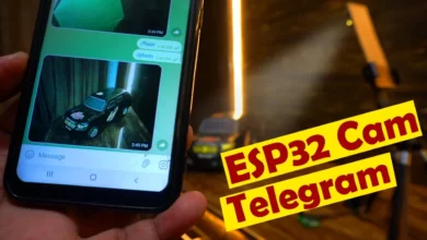
Send images to Google using ESP32 CAM, IoT Camera.
ESP32 CAM based Smart IoT Bell.
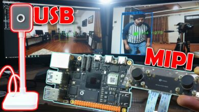
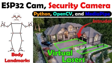
Object detection and identification using Python OpenCV Yolo V3
Amazon Links:
ESP32 Camera Module:
12v Adaptor:
Arduino Uno
Arduino Nano
Mega 2560:
Disclosure: These are affiliate links. As an Amazon Associate I earn from qualifying purchases.
What is ESP32:
ESP32 is a series of low-cost, low-power system on a chip microcontrollers with integrated Wi-Fi and dual-mode Bluetooth.
What is ESP32-cam?
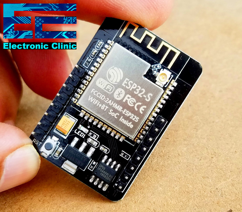
The ESP32-CAM is a small camera module with the ESP32-S chip that costs approximately $10. Besides the OV2640 camera, and several GPIOs to connect peripherals, it also features a microSD card slot that can be useful to store images taken with the camera or to store files to serve to clients.
ESP32-CAM ESP32 WIFI+Bluetooth Development Board Module w/ OV2640 Camera
Ultra-small 802.11b/g/n Wi-Fi + BT/BLE SoC module.Low-power dual-core 32-bit CPU for application processors.
Main frequency up to 240MHz, computing power up to 600 DMIPS.Built-in 520 KB SRAM, external 4M PSRAM.Supports interfaces such as UART/SPI/I2C/PWM/ADC/DAC.Support OV2640 and OV7670 cameras, built-in flash.
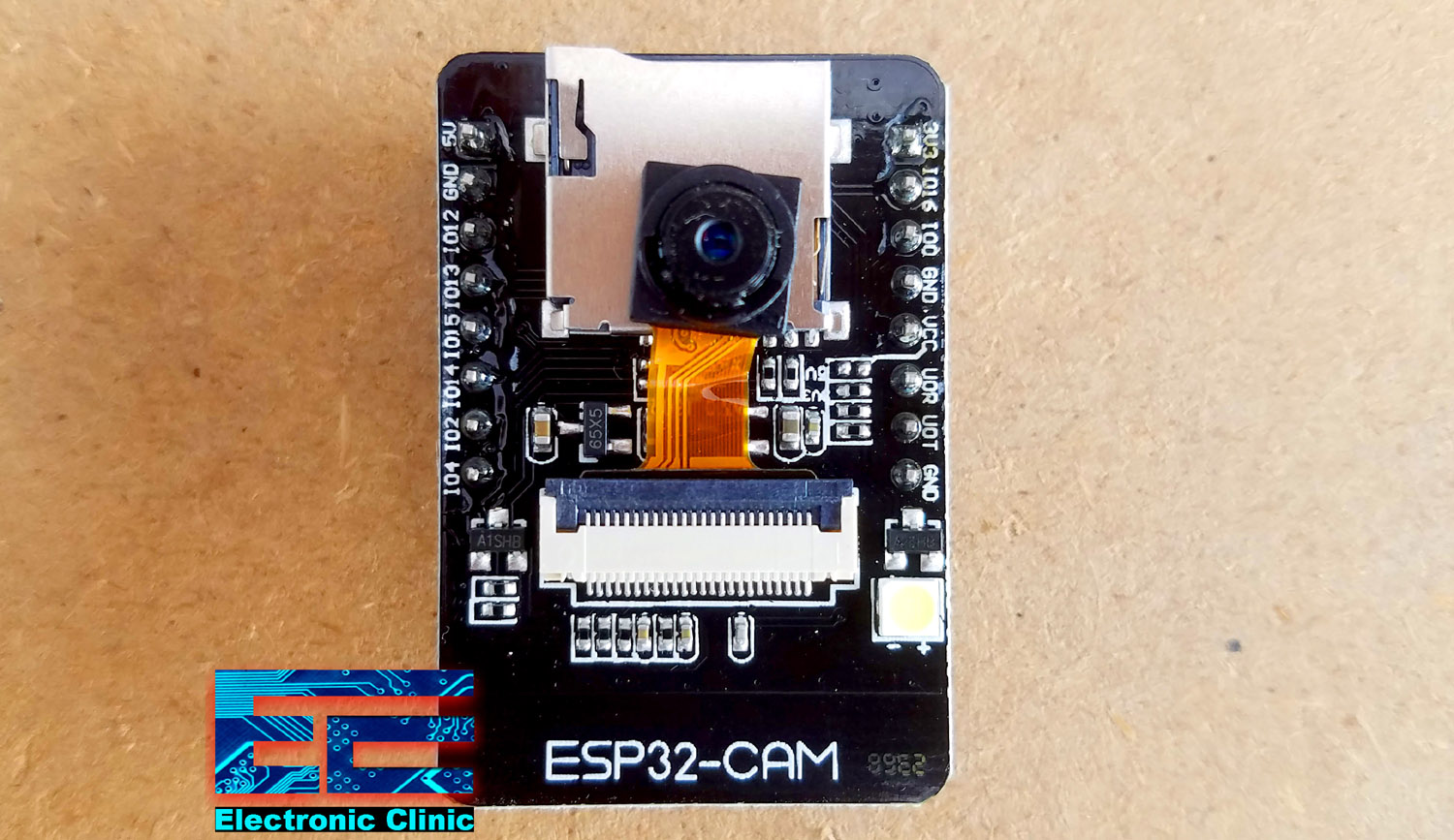
The ESP32-CAM is a small-sized camera module. The module can operate independently as a minimum system with a size of only 27*40.5*4.5mm and a deep sleep current of up to 6mA.
It can be widely used in various IoT applications. It is an ideal solution for IoT applications.
Features:
Ultra-small 802.11b/g/n Wi-Fi + BT/BLE SoC module.
Low-power dual-core 32-bit CPU for application processors.
Main frequency up to 240MHz, computing power up to 600 DMIPS.
Built-in 520 KB SRAM, external 4M PSRAM.
Supports interfaces such as UART/SPI/I2C/PWM/ADC/DAC.
Support OV2640 and OV7670 cameras, built-in flash.
Support image WiFi upload, support TF card.
Support multiple sleep modes, embedded Lwip and FreeRTOS.
Support STA/AP/STA+AP working mode.
Support Smart Config/AirKiss one-click distribution network, support secondary development.
It is suitable for home smart devices, industrial wireless control, wireless monitoring, QR wireless identification, wireless positioning system signals, and other applications.
Packaged in DIP and can be directly plugged into the backplane for quick production.
Specifications:
Material: Copper
Module model: ESP32-CAM
Package: DIP-16
Size: 27*40.5*4.5(±0.2)mm
SPI Flash: 32Mbit by default
RAM: Internal 520KB + external 4M PSRAM
BT: BT 4.2BR/EDR and BLE standards
WiFi: 802.11 b/g/n/e/i
Support interface: UARI, SPI, I2C, PWM
Support TF card: maximum support 4G
IO port: 9
Serial port rate: default 115200bps
Image output format: JPEG (only supported by OV2640), BMP, GRAYSCALE
Spectrum range: 2412-2484MHz
Antenna form: onboard antenna, gain 2dBi
Security: WPA/WPA2/WPAS-Enterprise/WPS
Power supply range: 5V
Working temperature: -20 ° C -85 ° C
Storage environment: -40°C-90°C, <90%RH
Package size: 5*5*3cm/1.96*1.96*1.18in
Package weight: 15g
Transmit power:
802.11 b: 17±2dBm (@11Mbps)
802.11 g: 14±2dBm (@54Mbps)
802.11 n: 13±2dBm (@MCS7)
Receive sensitivity:
CCK, 1 Mbps: -90dBm
CCK, 11 Mbps: -85dBm
6Mbps (1/2 BPSK): -88dBm
54Mbps (3/4 64-QAM): -70dBm
MCS7 (65Mbps, 72.2Mbps): -67dBm
Power consumption:
Turn off the flash: 180mA@5V
Turn on the flash and adjust the brightness to the maximum: 310Ma@5V
Deep-sleep: The lowest power consumption can reach 6mA@5V
Modern-sleep: up to 20mA@5V
Light-sleep: up to 6.7mA@5V
Packaged included:
1x ESP32-CAM WiFi Module with OV2640 Camera
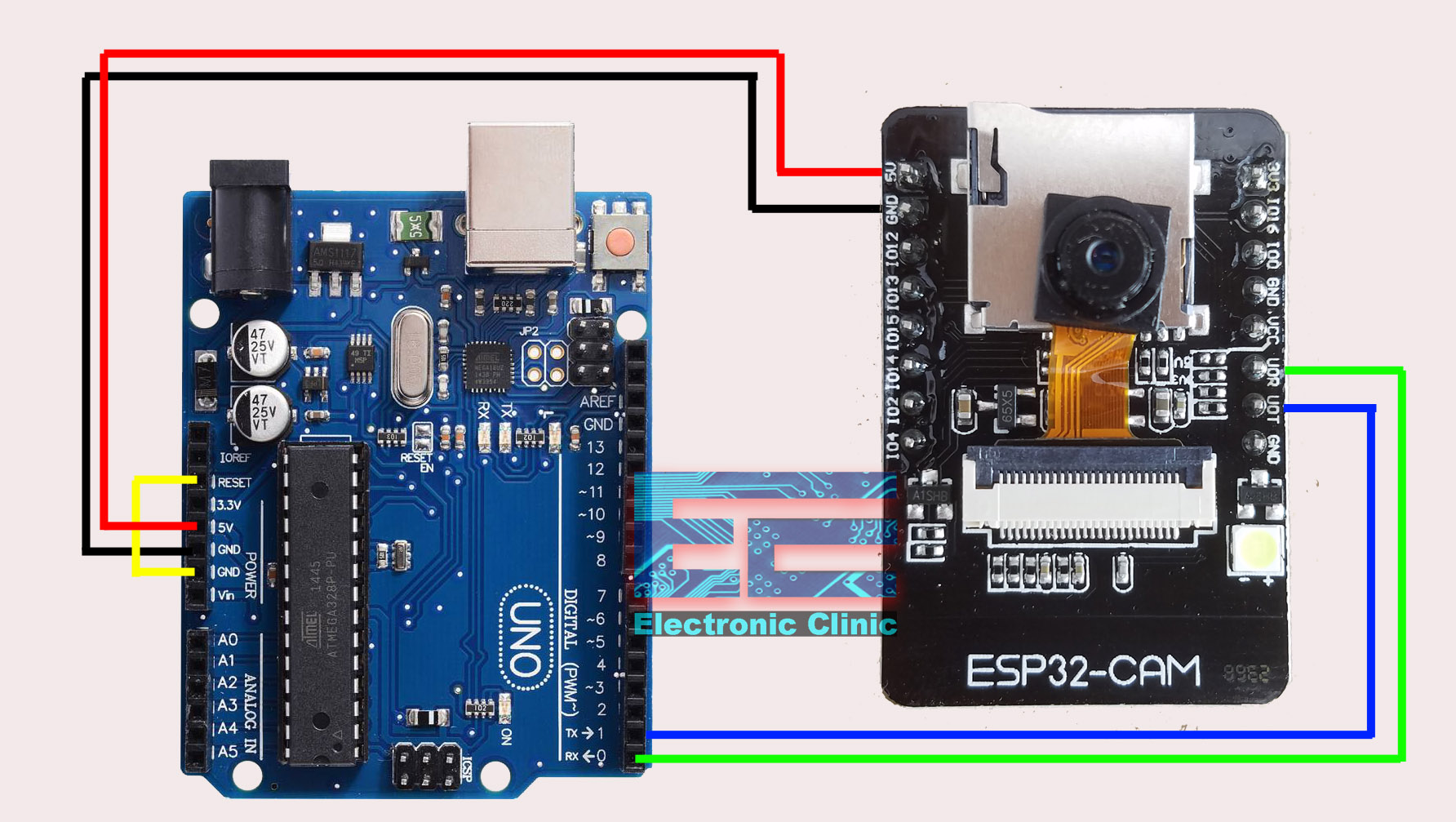
ESP32 connection with Arduino Uno or Arduino Nano:
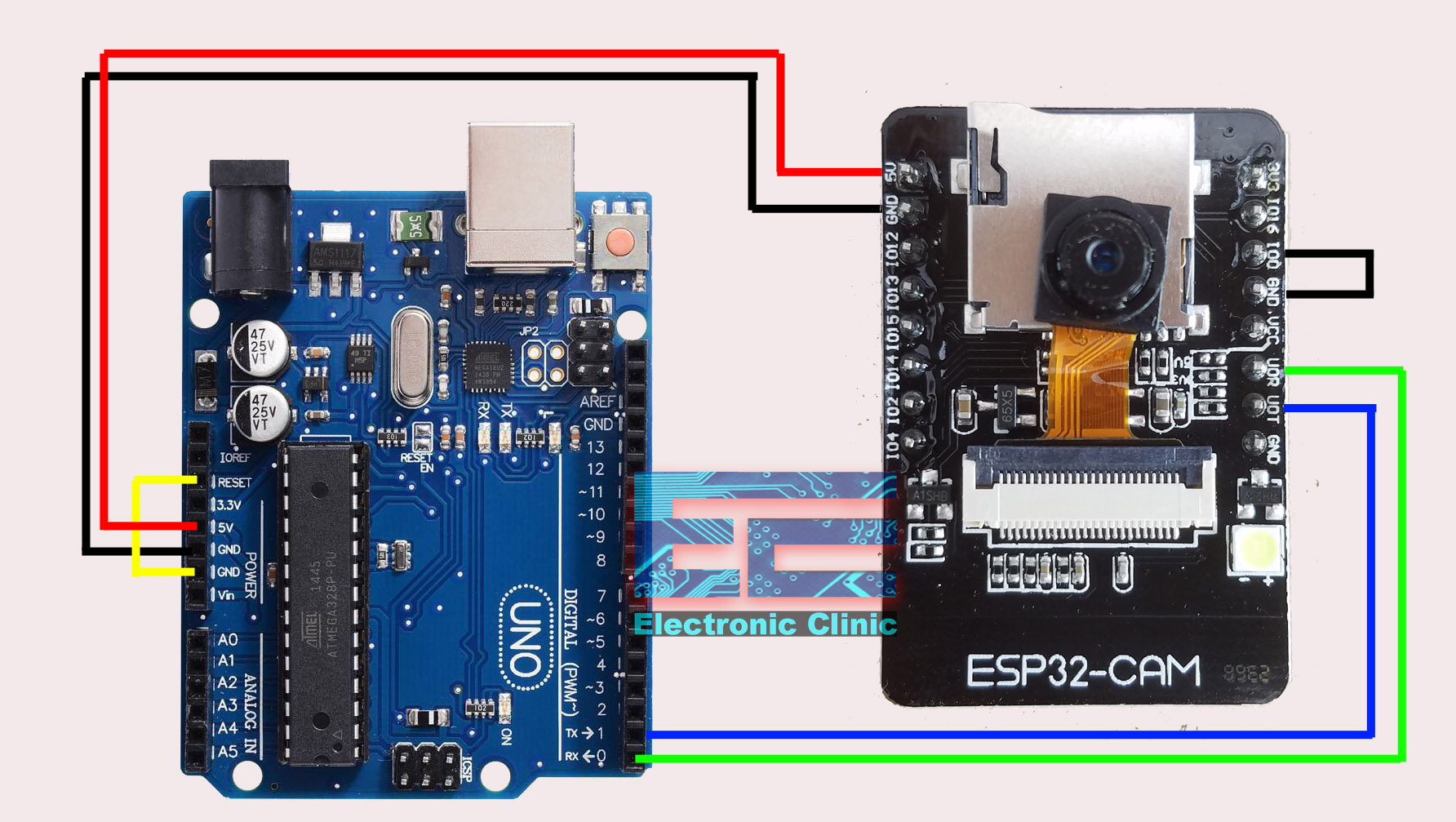
Connect the Reset Pin of the Arduino with the GND.
Connect the 100 pin of the ESP32 Cam with the GND Pin, for this you can use a female to female type jumper wire.
Connect the 5V and GND pins of the ESP32 Cam with the Arduino’s 5V and Ground.
Connect the Receive Pin of the ESP32 Cam with the RX pin of the Arduino.
Connect the Transmit Pin of the ESP32 Cam with the TX pin of the Arduino.
The ESP32 Cam interfacing with the Arduino is completed. Now, let’s go to the computer screen and install the ESP32 Cam board.
ESP32-Cam Board Manager Installation:
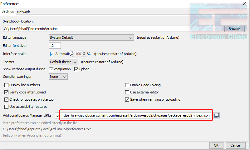
Make sure the latest version of the Arduino IDE is installed on your computer. Copy the link given below.
https://raw.githubusercontent.com/espressif/arduino-esp32/gh-pages/package_esp32_index.json
Now, open the Arduino IDE, click on the file menu and then click on the preferences and simply paste the URL.
Now click on the Tools menu, boards, and click on the boards manager, search for the ESP32 and install, this can take several minutes. Next check if the desired board is installed,
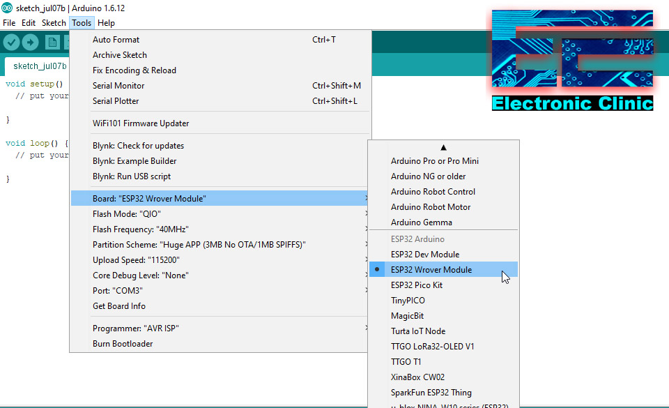
As you can see the ESP32 Wrover Module is available.
ESP32 Cam Settings:
Next, go to the Flash Mode and select QIO.
Next, select the Flash Frequency as the “40Mhz”
Next, Select the Partition Scheme as the Huge APP.
Next, Select 115200 as the Upload Speed and Finally
Select the Programmer “AVR ISP”
As you can see Port: “COM3”, this means that the Arduino board is connected with the Laptop through a USB Cable.
Click on the File Menu > Examples > ESP32 > Camera > CameraWebServer
Open the CameraWebServer Program.
Next, enter your SSID and password.
Select your Camera Model.
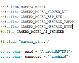
We are all set, now we can click on the upload button.
Now the next step is to remove the wire that we used to short the IO0 pin and ground.
Click on the Serial monitor. Press the pushbutton available on the backside of the ESP32 Cam.
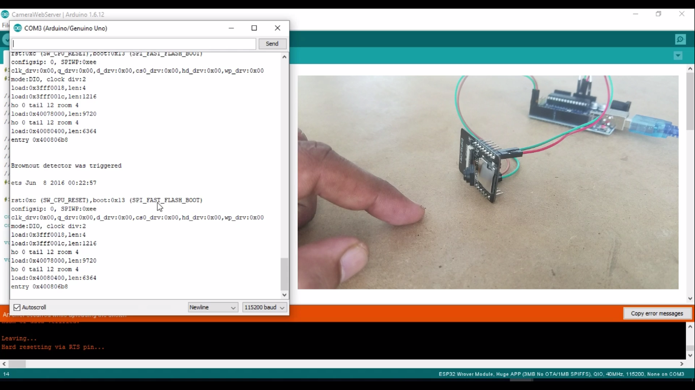
As you can see the ESP32 Cam is unable to connect with the WiFi and seems like if the ESP32 Camera Module is resetting automatically, this is just because the Arduino is not able to provide enough current to the ESP32 Cam Module. Sometimes you will see,
[e][camera.c:1049] camera_probe(): detected camera not supported.
[e][camera.c:1249] esp_camera_init(): camera probe failed with error 0x20004
Now to fix these types of errors we can use an external 5V regulated Power supply to power up the ESP32 Module. So I am going to get 5V regulated power supply board based on the LM7805 Voltage regulator.
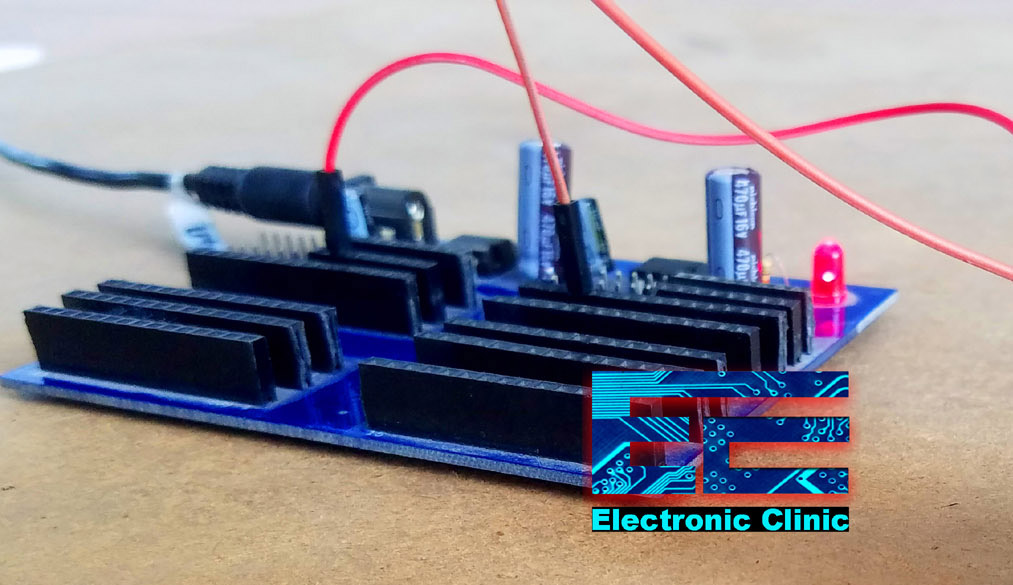
Connect the 5v pin of the ESP32 Cam with the 5V pin on the power supply, and make sure the power supply ground is connected with the ESP32 Camera Module ground pin…Finally, power up the Power supply board.
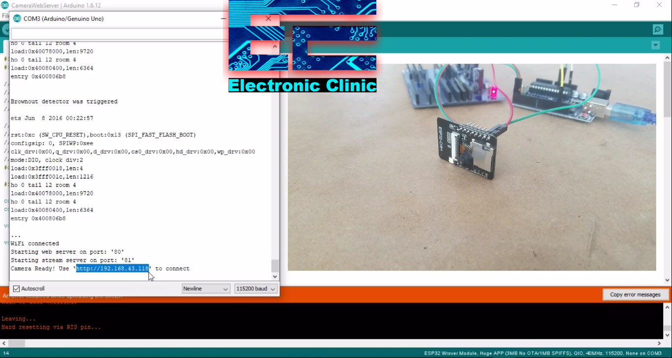
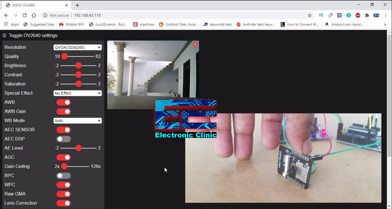
As you can see on the Serial Monitor, the ESP32 Camera Module is connected with the WiFi and on the screen, I can see my local IP address. Copy this link and Open the internet browser and paste this link. Finally, Click on the Start Stream button and that’s it.
So, this is how easily Arduino Uno or Arduino Nano can be used to program the ESP32-Cam Module. I hope you have learned something from this article. Don’t forget to Subscribe to my Website and my YouTube channel “Electronic Clinic”.
Watch Video Tutorial:
Discover more from Electronic Clinic
Subscribe to get the latest posts sent to your email.
Thank You, it was my problem 😉
Thank You Shahzada Fahad! Easy to follow! Trouble free!
im unable to select “programmer as AVR-ISP”.What is the possible solution on this problem? Can u plz tell?
Programmer has to do with UNO, so before you do the ESP Settings, go to tools, select UNO, then set Programmer to ISP-AVR.
Then, you can proceed with setting the ESP settings. Don’t worry about setting Programmer for ESP32.
Hope this helped. Tony
Shouldn’t TX connect to RX and RX to TX? It is logical to assume that the RECEIVE pin of one device receives what is transmitted from the TRANSMIT pin of the other device. Is this incorrect?
I can’t find the LM7805 Voltage regulator same like yours.
I get a “sketch too big” compile error. Is there a way around that?
Did you get a solution ? I am facing the same problem !
A fatal error occurred: Failed to connect to ESP32: Invalid head of packet (0x65)
Jim and 11thd, the answer to “sketch too big”is answered in the description, but not explained, in the Arduino IDE:
Next, Select the Partition Scheme as the Huge APP.
Selecting Huge APP reserves more memory for your sketch.
Succeeded..!! But it gets Stop aftew few seconds and screen gets black
Serial port COM9
Connecting………………………………..
A fatal error occurred: Failed to connect to ESP32: No serial data received.