ESP32 CAM Smart IoT Bell Circuit Diagram and Programming
Last Updated on September 21, 2024 by Engr. Shahzada Fahad
Table of Contents
ESP32 CAM Smart IoT Bell:
ESP32 CAM Smart IoT Doorbell and Door Lock- In this article, you will learn how to make a Smart IoT Bell and Door Lock project using ESP32 Cam Module, Electronic Door Lock, and Blynk Application. From the very beginning, the ESP32 camera module has been one of my favorite camera modules, which I have been frequently using in all of my ESP32 Cam based projects. I have recently used the ESP32 camera with Google Drive. I have applied two methods during this project. In my first method, I used to send images directly on Google Drive, whereas according to the second method, images were sent on Google Drive when the IR sensor was activated. I have previously comprehensively explained this project.
I also used it for opening the Electronic Door lock using the Human Face recognition technique and I have also used the same camera module for the live video streaming using the Blynk application. These previously designed projects will really help you in getting started with the ESP32 CAM Module.
If you are using the ESP32 CAM module for the first time, then you might have come across some issues, I have also faced the same issues and that’s why I have written a complete article about it, and I highly recommend you should read my getting started article on the ESP32 CAM issues and how to solve them.
Ordinary doorbells are generally of a very boring type. Inmates do not have any idea who is at the door. Besides, you might have also experienced people who have an unpleasant habit of aimlessly pressing the doorbell and then running away quickly. When any of the inmates opens the door, he or she finds none outside.
Moreover, you are well aware of the fact how alarmingly the crime ratio has increased nowadays. In case only a female member of a family is present at home and suddenly the doorbell rings, you can better imagine a serious nature problem she might come up with, particularly when she is unaware of who is at the door. But with my designed project, she will know exactly, who is at the door.
My designed smart doorbell and door lock system is specifically handy for disabled people because whenever the doorbell rings, the disabled person can watch on his mobile who is at the door. If he wants to allow that person, he or she can press a button on the Blynk application to open that electronic door lock.
Now you can decide for yourself how useful this system can turn out to be for you, guys. And the interesting point about the system is that it is pretty cheap. Anybody can design this system easily if my instructions are followed carefully.
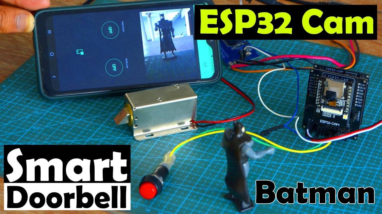
Before, I am going to explain the circuit diagram, Blynk App designing, and programming. First let’s watch the ESP32 Cam based Smart IoT Bell and Door Lock project in Action.
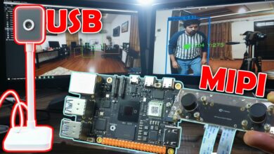
check my new project on ” ESP32 CAM and Python OpenCV Yolo V3 for object detection and identification”
Anyway, in today’s article, I am going to use the ESP32 CAM in a very practical way. We will be designing the ESP32 CAM Smart IoT Bell. Let me tell you in detail what is ESP32 CAM based Smart IoT Bell is and how it works?

ESP32 CAM Smart IoT Bell is a semi-automatic Door control system based on the Blynk application. When the Bell button is pressed a notification message is sent to the concerned person. He can then open the Blynk application and can check who is at the door, he can even capture the image of that person. On the Blynk application, there are buttons that can be used to capture the image and also to Open and Close the Electronic Door Lock. For the 12V Electronic door lock, I have used a relay module. You can use a readymade relay module or you can design and make your own relay module.
Components Required:
- ESP32 cam
- Relay module
- 10KΩ Resistor
- Push-button
- Jumper wires
Amazon Links:
12v Electronic Door Lock / Elock / Solenoid Lock:
Disclosure: These are affiliate links. As an Amazon Associate I earn from qualifying purchases.
ESP32 CAM Smart IoT Bell Circuit diagram:
- Connect the ground of the relay module with the ground of the ESP32 cam module
- Connect the signal pin of the relay module with the GPIO12 of the ESP32 CAM
- Connect the push button with the GPIO13 of the ESP32 CAM

Download PCB boards Gerber files:
ESP32 CAM Smart IoT Bell, Blynk app Designing:
You can start by downloading the Blynk application from the PlayStore and the amazing thing is it’s absolutely free and you get enough energy which is sufficient for most of the projects. If you want more energy, then you can purchase it. Anyway, for this project you don’t need to pay. Simply download and install the Blynk application.
First open the Blynk app in the mobile and click on the new project.

Then give a name to the project Smart Door Bell and select ESP32 DEV board and click on the Create Button.

The authentication code will be sent on your registered email id, don’t share this code with anyone, and also don’t delete the email, as you will need this authentication code while writing the program.

Then click on the add button and add the image gallery.

After adding the image gallery we set the virtual pin 1 and click on the ok. In the image gallery we will get the image from the ESP32 CAM.

Then we will click on the notification button and add it to the screen.
Then click two styled buttons.

Then click on the one button and select the pin gp14 and give a name to the button.

Then click on another button and select the pin gp12 and give the name to the button as gate opener.

Click on the Image gallery and select virtual V1.
ESP32 CAM Issues and how to fix them:
Before, I am going to share the code, first I am going to talk about some ESP32 CAM issues. When it comes to uploading the program most of the guys faces a lot of issues and that’s why I get a lot of messages from boys and girls. So, I decided to talk about these issues in detail.
You have to setup your ESP32 CAM exactly the same way as per my instructions and I am sure if you follow everything correctly then you will be able to fix all the issues and problems.
Before, you upload the program into the ESP32 CAM first, you need to select the correct module which is the ESP32 Wrover Module.

Then we set the flash mode to QIO

After that we will set the flash frequency to 80MHz.

If you compile the code and you see this type of error
Sketch too big; see http://www.arduino.cc/en/Guide/Troubleshooting#size for tpis on reduing it

Then it means that you have selected the limited memory, to fix this error/issue you have to change the memory setting to huge memory and this problem will be fixed.

After that you have to select the upload speed 921600.
Then you have to set the core debug level to none

Then you have to select the port number which is different in every computer.
There is another most common issue which is about the AVR ISP programmer. I oftenly hear this from guys that they are not able to see the AVR ISP programmer. The same thing has happened to me, I fixed this issue by changing the Arduino IDE. I used the Arduino IDE version 1.6.12, and in this version of the Arduino IDE I was able to find the AVR ISP Programmer. So, if you are not able to the AVR ISP Programmer then simply go ahead and install the 1.6.12 version of the Arduino IDE.

Now the setup is completed for the programming and we will write the code and upload in the ESP32 cam.
If you still see an error
Error compiling for board ESP32 Wrover Module

Then it means that you have installed multiple Arduino IDEs. Remove all the Arduino IDEs and install only one IDE this problem will be resolved.
ESP32 CAM IoT Bell Complete Code:
for this project, you will also need
app_httpd.cpp
camera_index.h
camera_pins.h
and the main code which you can see below.
You will need to keep all these files inside the same folder.
|
1 2 3 4 5 6 7 8 9 10 11 12 13 14 15 16 17 18 19 20 21 22 23 24 25 26 27 28 29 30 31 32 33 34 35 36 37 38 39 40 41 42 43 44 45 46 47 48 49 50 51 52 53 54 55 56 57 58 59 60 61 62 63 64 65 66 67 68 69 70 71 72 73 74 75 76 77 78 79 80 81 82 83 84 85 86 87 88 89 90 91 92 93 94 95 96 97 98 99 100 101 102 103 104 105 106 107 108 109 110 111 112 113 114 115 116 117 118 119 120 121 122 123 124 125 126 127 128 129 130 131 132 133 134 135 136 137 138 139 140 141 142 143 |
#include "esp_camera.h" #include <WiFi.h> #include <WiFiClient.h> #include <BlynkSimpleEsp32.h> // // WARNING!!! PSRAM IC required for UXGA resolution and high JPEG quality // Ensure ESP32 Wrover Module or other board with PSRAM is selected // Partial images will be transmitted if image exceeds buffer size // // Select camera model #define CAMERA_MODEL_AI_THINKER // Has PSRAM #include "camera_pins.h" #define button 13 #define PHOTO 14 #define LED 4 #define lock 12 const char* ssid = "AndroidAP3DEC"; //Wifi Name const char* password = "electroniclinic"; //Wifi Password char auth[] = "JDsObzId8L936DT64syOG1RciAjT3Rg6"; //Authentiation code sent by Blynk String local_IP; void startCameraServer(); void takePhoto() { digitalWrite(LED, HIGH); delay(200); uint32_t randomNum = random(50000); Serial.println("http://"+local_IP+"/capture?_cb="+ (String)randomNum); Blynk.setProperty(V1, "urls", "http://"+local_IP+"/capture?_cb="+(String)randomNum); digitalWrite(LED, LOW); delay(1000); } void setup() { Serial.begin(115200); pinMode(LED,OUTPUT); pinMode(lock,OUTPUT); pinMode(button, INPUT_PULLUP); Serial.setDebugOutput(true); Serial.println(); camera_config_t config; config.ledc_channel = LEDC_CHANNEL_0; config.ledc_timer = LEDC_TIMER_0; config.pin_d0 = Y2_GPIO_NUM; config.pin_d1 = Y3_GPIO_NUM; config.pin_d2 = Y4_GPIO_NUM; config.pin_d3 = Y5_GPIO_NUM; config.pin_d4 = Y6_GPIO_NUM; config.pin_d5 = Y7_GPIO_NUM; config.pin_d6 = Y8_GPIO_NUM; config.pin_d7 = Y9_GPIO_NUM; config.pin_xclk = XCLK_GPIO_NUM; config.pin_pclk = PCLK_GPIO_NUM; config.pin_vsync = VSYNC_GPIO_NUM; config.pin_href = HREF_GPIO_NUM; config.pin_sscb_sda = SIOD_GPIO_NUM; config.pin_sscb_scl = SIOC_GPIO_NUM; config.pin_pwdn = PWDN_GPIO_NUM; config.pin_reset = RESET_GPIO_NUM; config.xclk_freq_hz = 20000000; config.pixel_format = PIXFORMAT_JPEG; // if PSRAM IC present, init with UXGA resolution and higher JPEG quality // for larger pre-allocated frame buffer. if(psramFound()){ config.frame_size = FRAMESIZE_UXGA; config.jpeg_quality = 10; config.fb_count = 2; } else { config.frame_size = FRAMESIZE_SVGA; config.jpeg_quality = 12; config.fb_count = 1; } // camera init esp_err_t err = esp_camera_init(&config); if (err != ESP_OK) { Serial.printf("Camera init failed with error 0x%x", err); return; } sensor_t * s = esp_camera_sensor_get(); // initial sensors are flipped vertically and colors are a bit saturated if (s->id.PID == OV3660_PID) { s->set_vflip(s, 1); // flip it back s->set_brightness(s, 1); // up the brightness just a bit s->set_saturation(s, -2); // lower the saturation } // drop down frame size for higher initial frame rate s->set_framesize(s, FRAMESIZE_QVGA); WiFi.begin(ssid, password); while (WiFi.status() != WL_CONNECTED) { delay(500); Serial.print("."); } Serial.println(""); Serial.println("WiFi connected"); startCameraServer(); Serial.print("Camera Ready! Use 'http://"); Serial.print(WiFi.localIP()); local_IP = WiFi.localIP().toString(); Serial.println("' to connect"); Blynk.begin(auth, ssid, password); } void loop() { // put your main code here, to run repeatedly: Blynk.run(); int buttonState = digitalRead(button); if(buttonState==LOW) { Serial.println("Send Notification"); Blynk.notify("There is Someone at the door"); Serial.println("Capture Photo"); takePhoto(); delay(1000); Serial.println(buttonState); } if(digitalRead(PHOTO) == HIGH){ Serial.println("Capture Photo"); takePhoto(); } // if(digitalRead(V1)){ //digitalWrite(lock,HIGH); // } // else //{ // digitalWrite(lock,LOW); // // } } |
Watch Video Tutorial:
Discover more from Electronic Clinic
Subscribe to get the latest posts sent to your email.