ESP32 Cam Face Recognition Door Lock System circuit and programming
Last Updated on August 25, 2024 by Engr. Shahzada Fahad
Table of Contents
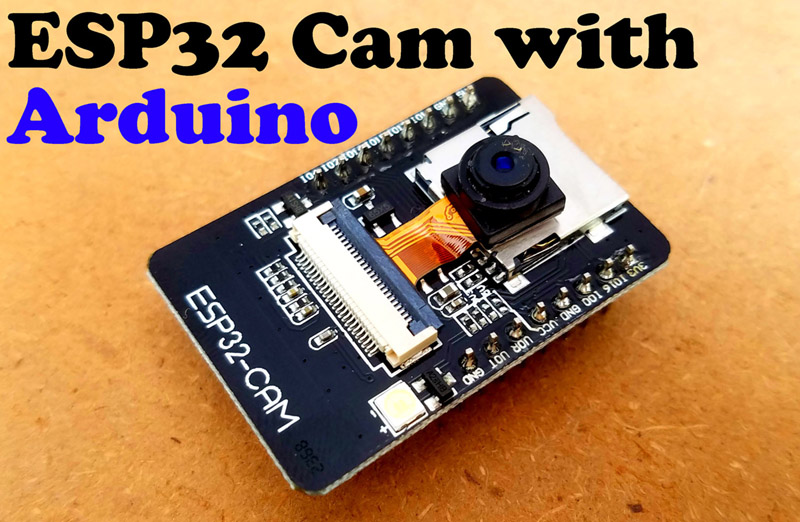
ESP32 Cam Face Recognition, Description:
ESP32 Cam Face Recognition Door Lock System– This is my third tutorial on the ESP32 Camera module. In this tutorial, you will learn how to make Face Recognition based Door Lock Control system using ESP32 Camera Module and a 12V electronic lock. For the Authorized person, the onboard white LED is turned ON and also the electronic lock is opened. This ESP32 Camera based face recognition door lock control system depends on my previous two tutorials.
In my first video tutorial I explained how to program the ESP32 Camera using the Arduino IDE, In this tutorial, I covered the basic settings including the ESP32 Camera board manager installation and I also explained how to fix the most common errors including the Detected Camera not supported and the Camera Probe failed with error 0x20004, I also explained some other issues. You should read this article, if you are using the ESP32 Cam for the first time, otherwise you won’t be able to upload the program.
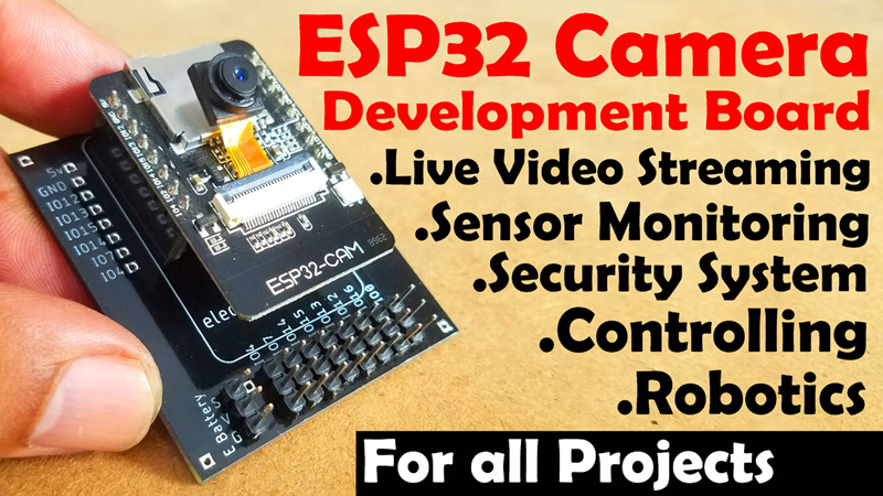
While in my second tutorial, I designed development board for the ESP32 Camera Module, so that the ESP32 Cam Module can be easily used with other I/O devices. So, I high recommend first read my previous two tutorials and then you can resume from here. Because in this tutorial, I will not explain the things, which I have already explained in my previous two tutorials. In this tutorial, I will only explain the new things including the modified circuit diagram, Interfacing, and programming.
check my new project on ” ESP32 CAM and Python OpenCV Yolo V3 for object detection and identification”
Without any further delay, let’s get started!!!
Amazon Links:
12v Electronic Door Lock / Elock / Solenoid Lock:
Disclosure: These are affiliate links. As an Amazon Associate I earn from qualifying purchases.
ESP32 CAM Face Recognition Project Circuit Diagram:

This is the schematic of the top PCB board. As you can see there is nothing complicated. Male Headers are connected with the Power Supply and I/O pins of the ESP32 Camera Module. The SV3 and SV4 male headers are used to make connection with the bottom circuit board. The JP1 and JP2 male headers are used to connect 3.3V and 5v Lipo Battery. While all the other male headers are used for interfacing Sensors and other output devices.
The top circuit remains the same; I didn’t even change a single connection. Now let’s have a look at the bottom circuit.

The 5V regulated power supply and the headers connections with the ESP32 Camera module remains the same. This time I added a one channel relay module which is used to control the electronic lock. The One Channel relay module is controlled using the IO Pin 12 of the ESP32 Camera module. The onboard white LED is connected with the IO4.
Following are the final circuit boards, which I have already explained in my previous article.

High quality & Only 24 Hours Build time
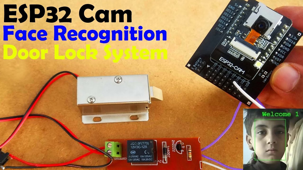
Using these top and bottom circuit boards, we can easily connect different types of IO devices and can monitor and control different electronic sensors and output devices without any problem. As in this tutorial is about the door lock control system and for this we will need an electronic lock that we can control through electrical signals.

You can see a 12V Electronic Lock provided with two Red and Black wires. Red is the 12V wire and of course Black is the ground wire. When these wires of the Electronic Lock are connected with the 12Vdc power supply the Electronic Lock will get open. You can see I have soldered a female type power jack. You might be wondering why have I cut the Red wire?
If you don’t cut this wire and connect the 12Vdc power supply the Electronic Lock will remain Open forever until you disconnect the 12V power supply. For the automatic control of the Electronic Lock we need to cut one of the two wires. So I selected the Red wire and cut it. Now if you connect the 12Vdc power supply with the DC Female Power jack and you touch the two heads of the Red wire, the Electronic Lock open and if you disconnect the two heads of the red wire the Electronic Lock will close again. So by connecting and disconnecting the red wires we can control the Electronic Lock. Instead, of manual connecting and disconnecting these red wires, we will use a relay.

The Red wires are connected with the 12V SPDT Type relay Normally Open and Common contacts. Now by turning ON and turning OFF this relay the Electronic Lock can be controlled automatically using the ESP32 Cam Module. You can use a readymade relay module or you can make the one by yourself by following the circuit diagram. Now, to control this relay we will need to connect this with the ESP32 Camera module.

I soldered the 12V and GND wires from the relay module with the 12V and Ground points of the power supply and connected the relay module input wire with the IO12 of the ESP32 Camera module.

I completed my connections as per the circuit diagram already explained. Now let’s have a look at the programming.
ESP32 CAM Face Recognition and Door Lock Programming:
Before, you are going to start the programming, first of all, make sure you have installed the ESP32 Cam Board.
|
1 2 3 4 5 6 7 8 9 10 11 12 13 14 15 16 17 18 19 20 21 22 23 24 25 26 27 28 29 30 31 32 33 34 35 36 37 38 39 40 41 42 43 44 45 46 47 48 49 50 51 52 53 54 55 56 57 58 59 60 61 62 63 64 65 66 67 68 69 70 71 72 73 74 75 76 77 78 79 80 81 82 83 84 85 86 87 88 89 90 91 92 93 94 95 96 97 98 99 100 101 102 103 104 105 106 107 108 109 110 111 112 113 114 115 116 117 118 119 120 121 122 123 124 125 126 127 128 129 130 131 132 133 134 135 136 137 138 139 140 141 142 143 144 |
/********************************************************************************** TITLE: ESP32 CAMERA Face Recognition Door Lock System ***************************************************************************************/ #include "esp_camera.h" #include <WiFi.h> // // WARNING!!! PSRAM IC required for UXGA resolution and high JPEG quality // Ensure ESP32 Wrover Module or other board with PSRAM is selected // Partial images will be transmitted if image exceeds buffer size // // Select camera model //#define CAMERA_MODEL_WROVER_KIT //#define CAMERA_MODEL_ESP_EYE //#define CAMERA_MODEL_M5STACK_PSRAM //#define CAMERA_MODEL_M5STACK_WIDE #define CAMERA_MODEL_AI_THINKER #include "camera_pins.h" #define RED 13 #define WHITE 4 // onboard white LED #define LOCK 12 const char* ssid = "AndroidAP7DF8"; const char* password = "jamshaid"; void startCameraServer(); boolean matchFace = false; boolean openLock = false; long prevMillis=0; int interval = 6000; //DELAY void setup() { pinMode(LOCK,OUTPUT); pinMode(RED,OUTPUT); pinMode(WHITE,OUTPUT); digitalWrite(LOCK,LOW); digitalWrite(RED,HIGH); digitalWrite(WHITE,LOW); Serial.begin(115200); Serial.setDebugOutput(true); Serial.println(); camera_config_t config; config.ledc_channel = LEDC_CHANNEL_0; config.ledc_timer = LEDC_TIMER_0; config.pin_d0 = Y2_GPIO_NUM; config.pin_d1 = Y3_GPIO_NUM; config.pin_d2 = Y4_GPIO_NUM; config.pin_d3 = Y5_GPIO_NUM; config.pin_d4 = Y6_GPIO_NUM; config.pin_d5 = Y7_GPIO_NUM; config.pin_d6 = Y8_GPIO_NUM; config.pin_d7 = Y9_GPIO_NUM; config.pin_xclk = XCLK_GPIO_NUM; config.pin_pclk = PCLK_GPIO_NUM; config.pin_vsync = VSYNC_GPIO_NUM; config.pin_href = HREF_GPIO_NUM; config.pin_sscb_sda = SIOD_GPIO_NUM; config.pin_sscb_scl = SIOC_GPIO_NUM; config.pin_pwdn = PWDN_GPIO_NUM; config.pin_reset = RESET_GPIO_NUM; config.xclk_freq_hz = 20000000; config.pixel_format = PIXFORMAT_JPEG; //init with high specs to pre-allocate larger buffers if(psramFound()){ config.frame_size = FRAMESIZE_UXGA; config.jpeg_quality = 10; config.fb_count = 2; } else { config.frame_size = FRAMESIZE_SVGA; config.jpeg_quality = 12; config.fb_count = 1; } #if defined(CAMERA_MODEL_ESP_EYE) pinMode(13, INPUT_PULLUP); pinMode(14, INPUT_PULLUP); #endif // camera init esp_err_t err = esp_camera_init(&config); if (err != ESP_OK) { Serial.printf("Camera init failed with error 0x%x", err); return; } sensor_t * s = esp_camera_sensor_get(); //initial sensors are flipped vertically and colors are a bit saturated if (s->id.PID == OV3660_PID) { s->set_vflip(s, 1);//flip it back s->set_brightness(s, 1);//up the blightness just a bit s->set_saturation(s, -2);//lower the saturation } //drop down frame size for higher initial frame rate s->set_framesize(s, FRAMESIZE_QVGA); #if defined(CAMERA_MODEL_M5STACK_WIDE) s->set_vflip(s, 1); s->set_hmirror(s, 1); #endif WiFi.begin(ssid, password); while (WiFi.status() != WL_CONNECTED) { delay(500); Serial.print("."); } Serial.println(""); Serial.println("WiFi connected"); startCameraServer(); Serial.print("Camera Ready! Use 'http://"); Serial.print(WiFi.localIP()); Serial.println("' to connect"); } void loop() { if(matchFace==true && openLock==false) { openLock=true; digitalWrite(LOCK,HIGH); digitalWrite(WHITE,HIGH); digitalWrite(RED,LOW); prevMillis=millis(); Serial.print("UNLOCK DOOR"); } if (openLock == true && millis()-prevMillis > interval) { openLock=false; matchFace=false; digitalWrite(LOCK,LOW); digitalWrite(WHITE,LOW); digitalWrite(RED,HIGH); Serial.print("LOCK DOOR"); } } |
This is the same exact program I used in my previous two tutorials, this time I made a few changes, I defined pins for the LEDs and the electronic lock. I also defined two variables matchFace and openLock of the type Boolean. I also defined an interval of 6 seconds. When the face is recognized, the electronic lock will remain open for 6 seconds.
In the end two conditions, which locks and unlocks the electronic lock and also controls the LEDs.

To compile and upload this code successfully, you will also need the app_httpd.cpp, camera_index.h, and camera_pins.h files.
Download Full Project Code
Now the final step is to upload the code. While uploading the code you might get an error as you can see in the picture below.

Don’t worry at all the code will upload anyway.
ESP32 Cam Face Recognition Door lock control system Project Testing:
I started off by powering up the Electronic Lock and the ESP32 Camera Module using a 12V adaptor. You will need the local IP address for the live video streaming using the same wifi network. I have already explained this in the first article.

So, I know about my local IP address. Turn ON the Face Detection and Face Recognition and click on the start stream button. Click on the Enroll face and start taking the samples, when everything is done successfully the electronic lock will open and also the white LED will turn ON.

It will take some samples, when the samples taking process is completed. Then the ESP32 Camera module can recognize the face and it will activate the Electronic Lock and will also turn ON the onboard White LED.

As you can see, everything is done successfully, if you find it hard to follow the steps, watch video tutorial, given in the end of this article.
You can see the text welcome on the recognized face. You can change this text, you can write the person name or you can write anything. For this you will need to open the app_httpd.cpp file. If you scroll down you will see the welcome text, you can change this, you can also see the intruder Alert! Text, this is for the unauthorized person, you can also change this text.

I hope you have learned something new from this article. Don’t forget to subscribe to my website and YouTube channel “Electronic Clinic”.
Watch Video Tutorial:
Other Image processing Projects:
Arduino Image Processing based Entrance lock Control System
Forest Fire Detection System using Arduino and Image Processing vb.net
Arduino Image processing CCTV camera system using VB.net
Arduino image processing Eye Pupil Tracking, how to make Haarcascade XML file
OCR Optical Character recognition using VB.net and Arduino
Discover more from Electronic Clinic
Subscribe to get the latest posts sent to your email.
I GO AN ERROR PLEASE HELP ME
IT’S ‘box_array_t’ {aka ‘struct tag_box_list’} has no member named ‘score’
Hello,
how to save scanned face in esp32 memory?
Hello, How to prevent photos to unlock the door because when I tested it was unlocking via photos?
Thanks