ESP32 SIM7600G 4G LTE Blynk and MLX90614 Infrared Temperature Sensor
Last Updated on September 14, 2026 by Engr. Shahzada Fahad
Table of Contents
ESP32, SIM7600G, and BLYK:
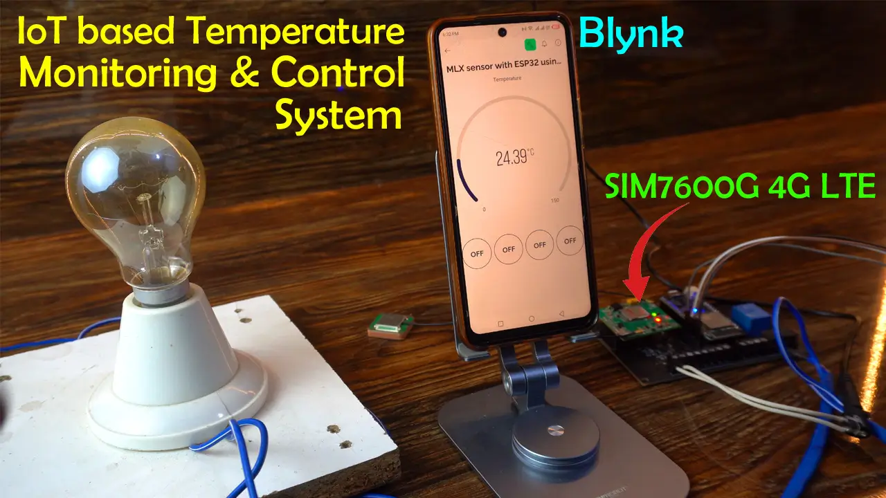
Today, we are going to make an IoT-based temperature monitoring and control system using the ESP32 WiFi + Bluetooth module, the SIM7600G 4G LTE module, the MLX90614 Non-Contact infrared temperature sensor, a 110/220Vac bulb, and the Blynk application.
I have already completed a similar project; in that project, I requested the temperature sensor value through a simple text command.
Additionally, I was controlling a 110/220Vac load with the help of commands sent via text messages. When a specified load was turned ON or OFF, the controller would send me a feedback message.
This was a beginner’s level project, and I made it just to demonstrate how to send and receive text messages using the SIM7600G 4G LTE module. Since I had to explain everything at a very basic level, thats why I did all the connections on a breadboard.
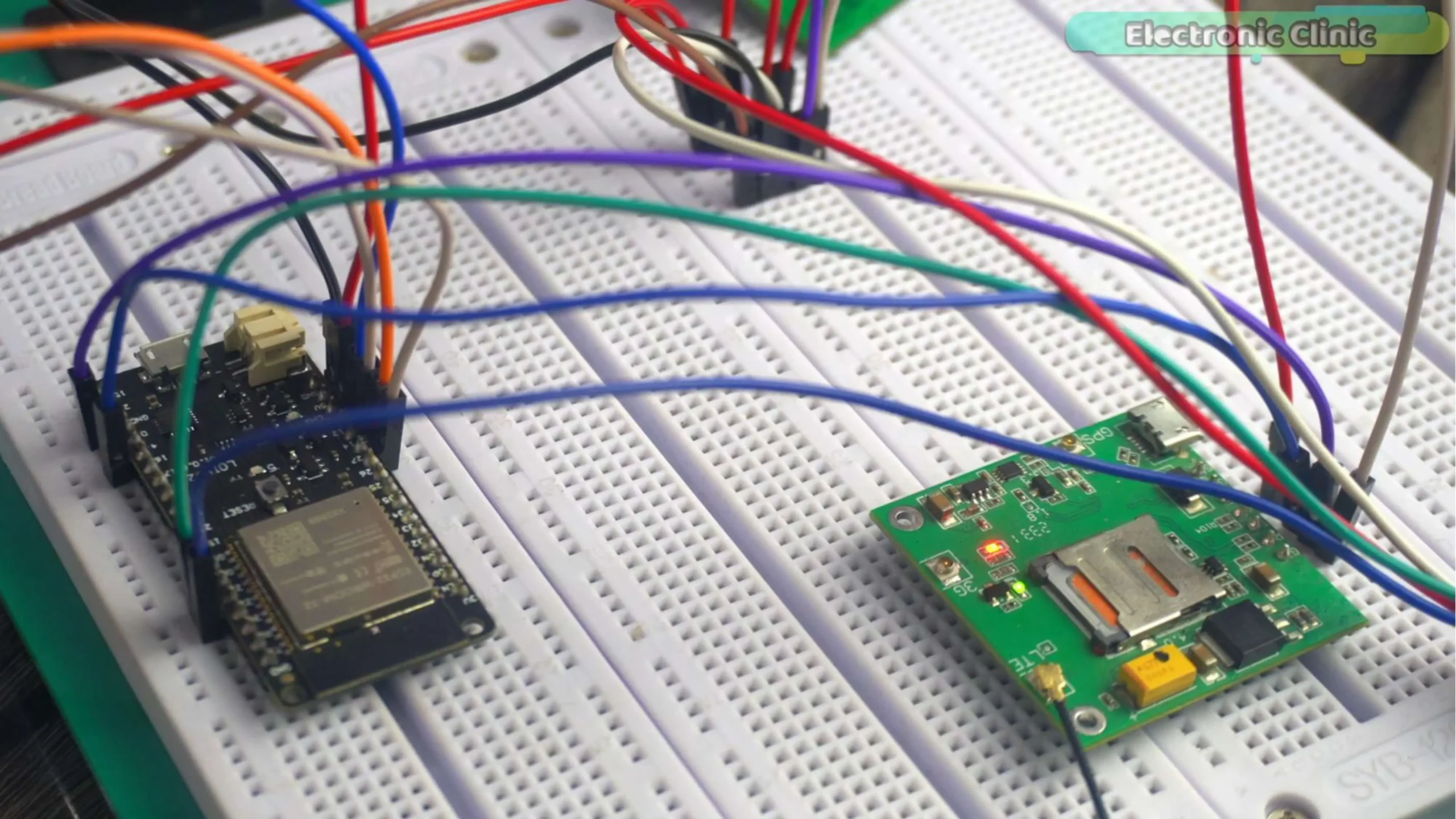
You can see the wiring is very congested and confusing. In this kind of wiring, there’s a high risk of damaging the components, and I don’t want the SIM7600G to be damaged due to any of my mistakes. Since I have to use the SIM7600G GSM module in many projects, I can’t afford to do this much wiring every time.
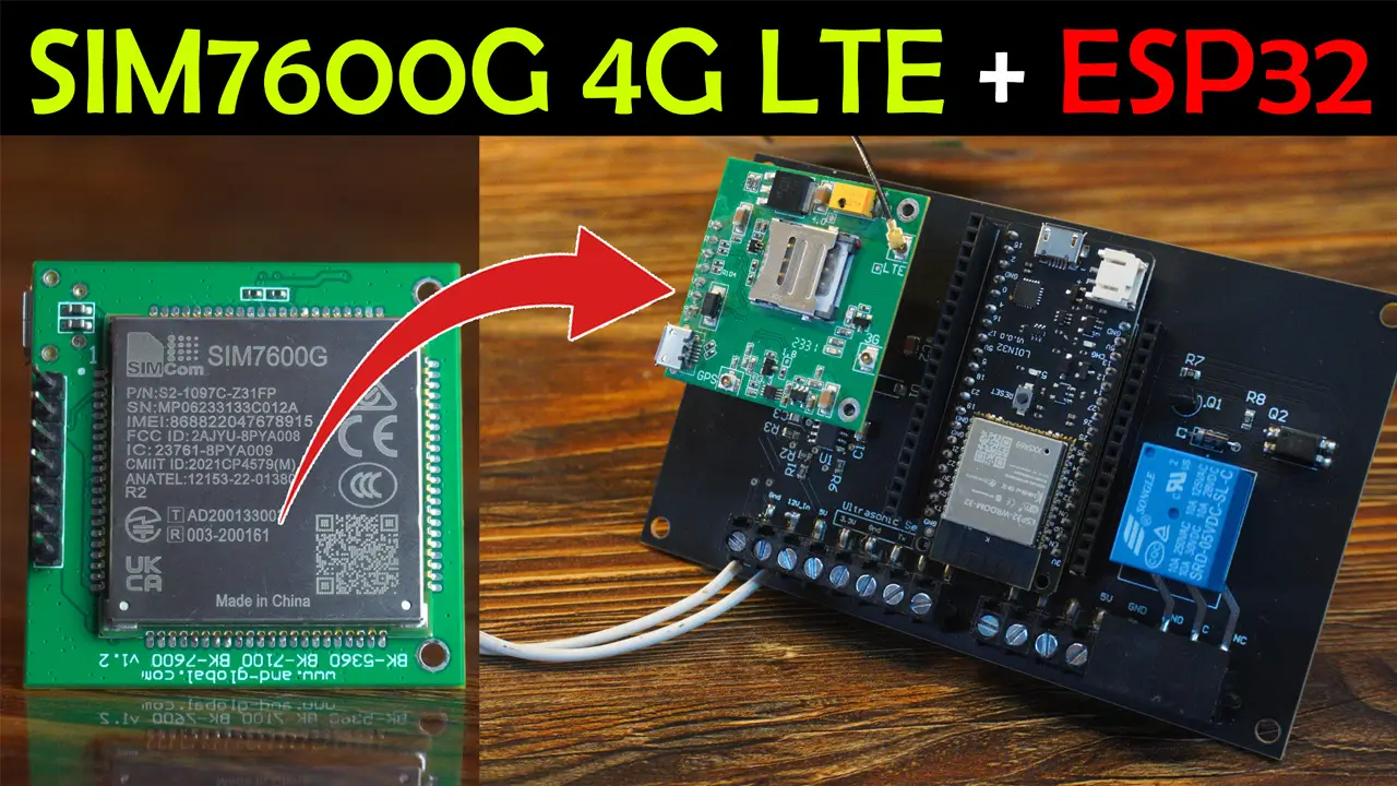
So, I decided to design my own ESP32 based development board for the SIM7600G; so that I can easily use it in basic, intermediate, and advanced-level projects. If you also want to make this development board, then you can watch my previous video and you can also read my article.
Amazon Links:
MLX90614 Non-contact Infrared Temperature Sensor
Other Tools and Components:
Super Starter kit for Beginners
PCB small portable drill machines
*Please Note: These are affiliate links. I may make a commission if you buy the components through these links. I would appreciate your support in this way!
Connect the VCC and GND wires of the MLX90614 non-contact infrared temperature sensor to the ESP32 3.3V and GND. Connect the SDA and SCL pins to the ESP32 GPIO 21 and 22.
The 5V and GND pins of the SIM7600G 4G LTE module are connected to the 5V and 3A power supply. And the Rx and Tx pins are connected to the ESP32 GPIOs 2 and 4.
This 5V SPDT relay is connected to the ESP32 GPIO 13.
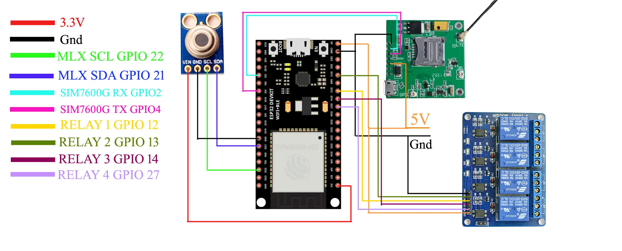
For the connections you can follow this circuit diagram. In the circuit diagram you can see the 5V and GND wires; connect these wires to a regulated 5V power supply; it should be at least 2 to 3A. Now let’s start with the Blynk Web Dashboard setup.
Blynk Web Dashboard Setup:
- While you are logged-in into your Blynk account.
- Click on the New Template.
- Write the Template Name.
- While ESP32 is selected as the Hardware type.
- Select the connection type as GSM.
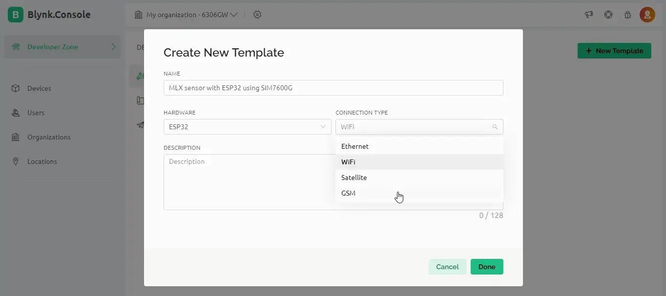
After this, all the steps are exactly the same. The only difference this time is that we selected GSM instead of WiFi in the connection type. Anyway, next click on the Datastreams. Then click on the New Datastream and select the Virtual Pin
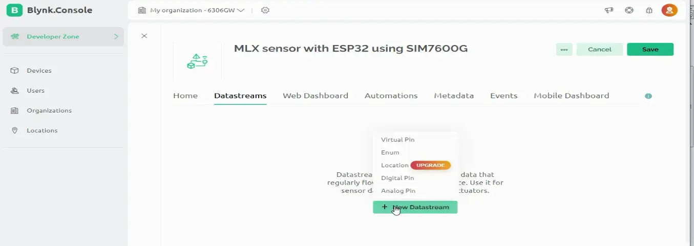
Then enter the required credentials and click on the create button.
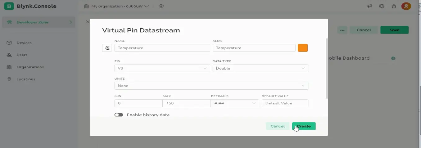
Then again click on the New Datastream
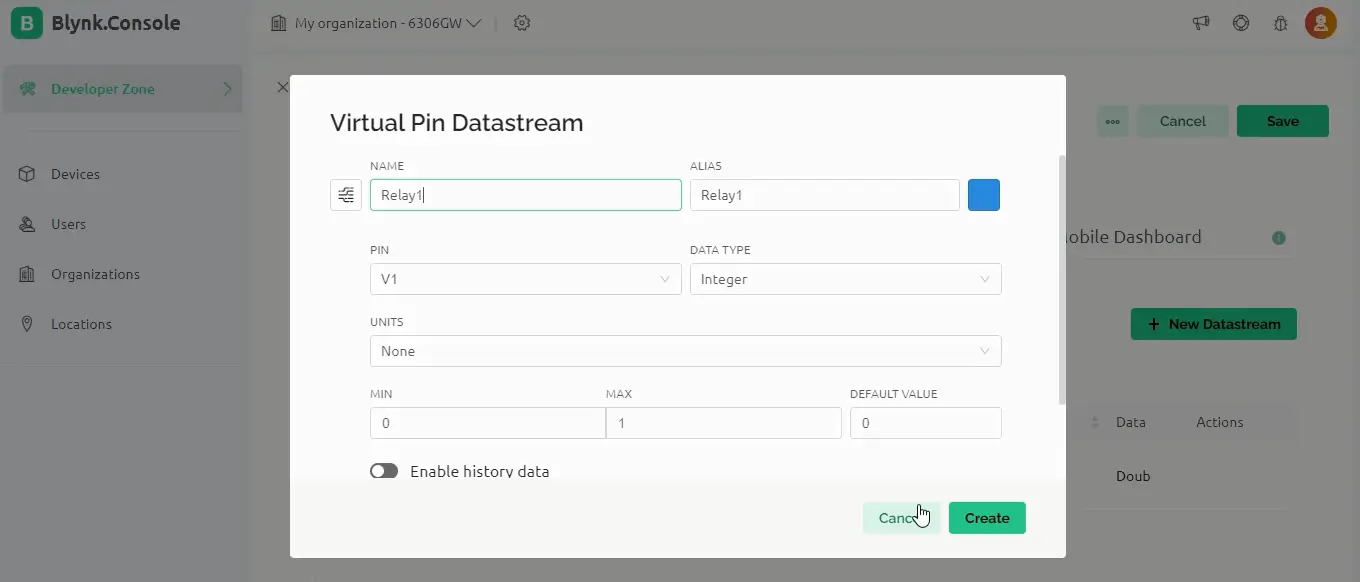
Repeat the same steps for all the other 3 relays and select virtual pins V2, V3, and V4.
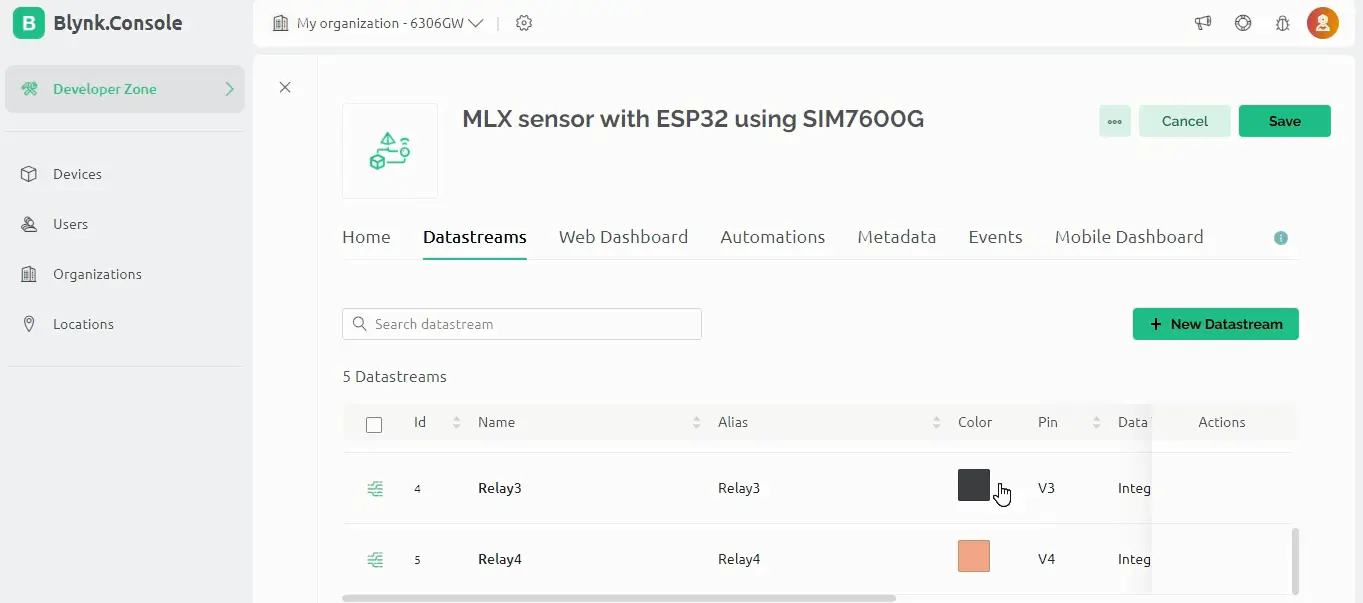
Then click on the web dashboard and double click on the Gauge to add it in the dashboard.
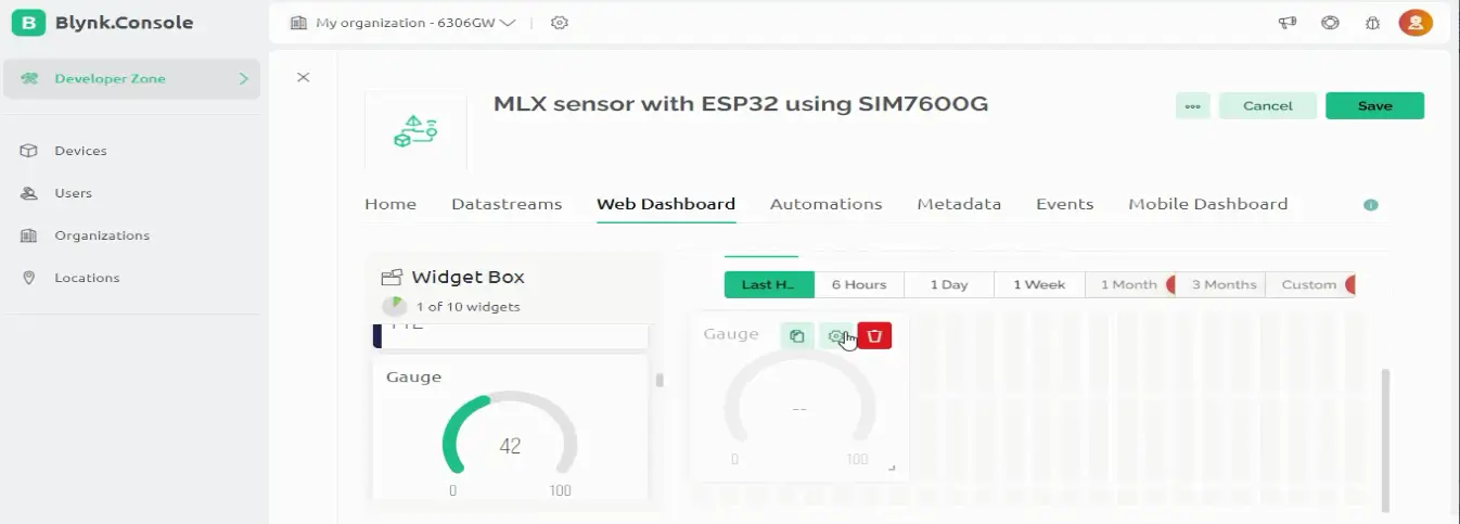
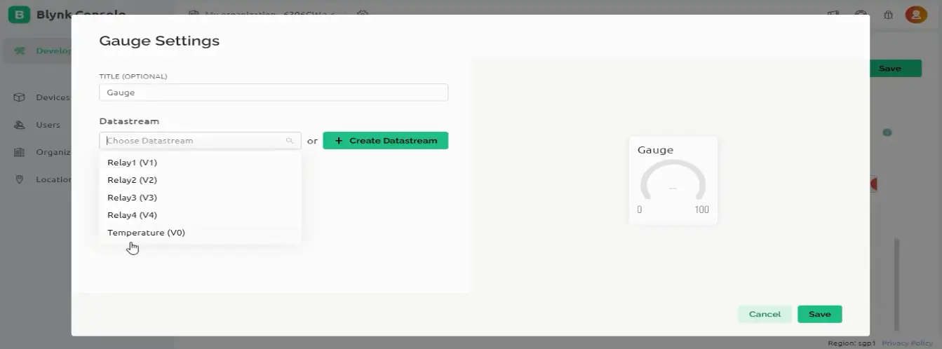
Click on the Gauge settings gear icon, and from the datastreams select V0.
Next, add a switch to the dashboard and repeat the same steps.
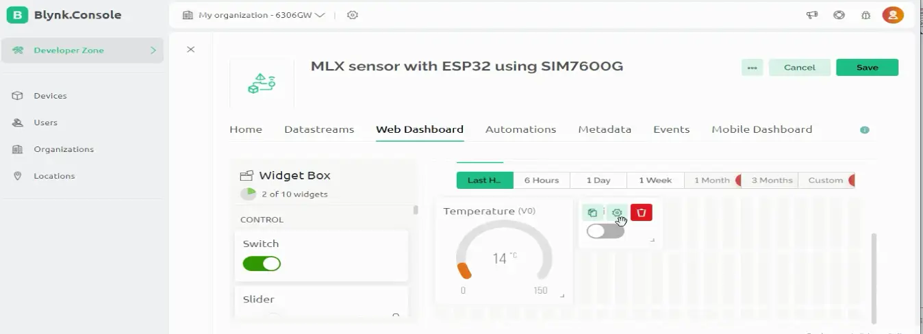
Click on the settings icon of the button and select the desired datastream. We created datastreams for 4 buttons.
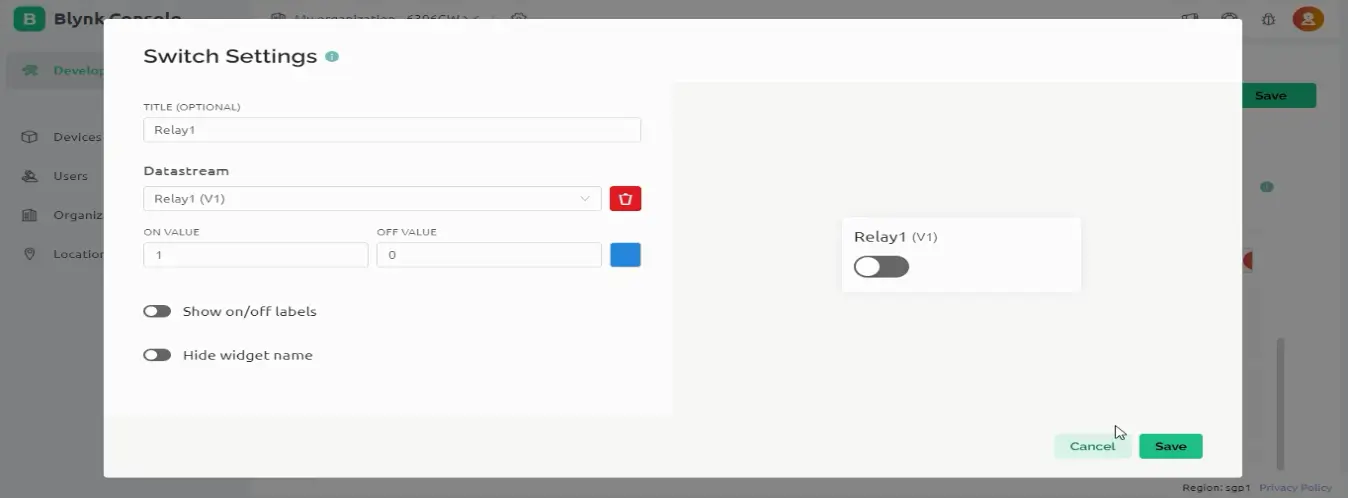
Repeat the same steps for the other 3 relays.
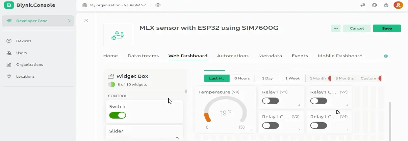
A Gauge and all the 4 buttons have been added. Now, we can click on the Save button.
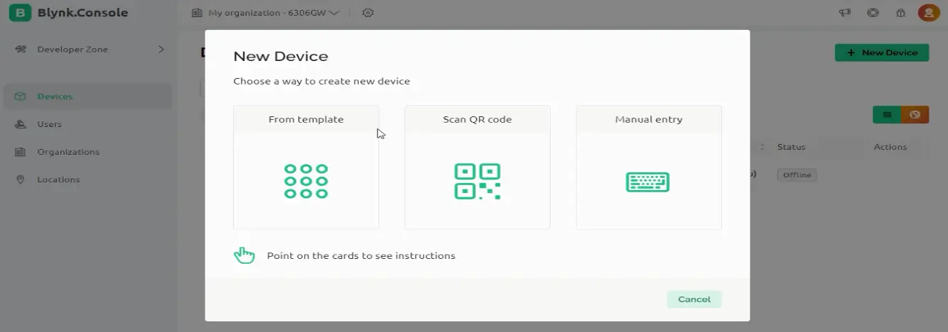
Now click on the devices and then click on new device and click on From template.
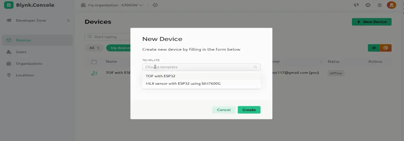
Now select the template “MLX sensor with ESP32 using SIM7600G” and click on the Create button.
Then copy the credentials
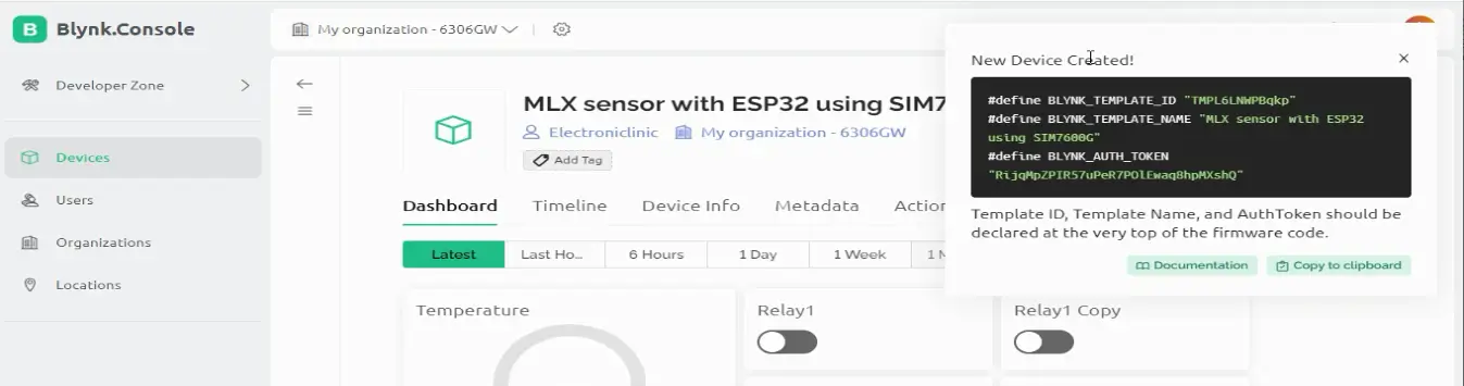
Paste these credentials in the code
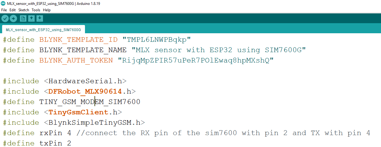
ESP32 SIM7600G Blynk Programming:
|
1 2 3 4 5 6 7 8 9 10 11 12 13 14 15 16 17 18 19 20 21 22 23 24 25 26 27 28 29 30 31 32 33 34 35 36 37 38 39 40 41 42 43 44 45 46 47 48 49 50 51 52 53 54 55 56 57 58 59 60 61 62 63 64 65 66 67 68 69 70 71 72 73 74 75 76 77 78 79 80 81 82 83 84 85 86 87 88 89 90 91 92 93 94 95 96 97 98 99 100 101 102 103 104 105 106 107 108 109 110 111 112 113 114 115 |
#define BLYNK_TEMPLATE_ID "TMPL6LNWPBqkp" #define BLYNK_TEMPLATE_NAME "MLX sensor with ESP32 using SIM7600G" #define BLYNK_AUTH_TOKEN "RijqMpZPIR57uPeR7POlEwaq8hpMXshQ" #include <HardwareSerial.h> #include <DFRobot_MLX90614.h> #define TINY_GSM_MODEM_SIM7600 #include <TinyGsmClient.h> #include <BlynkSimpleTinyGSM.h> #define rxPin 4 //connect the RX pin of the sim7600 with pin 2 and TX with pin 4 #define txPin 2 HardwareSerial SerialAT(1); DFRobot_MLX90614_I2C sensor; // instantiate an object to drive our sensor #if !defined(TINY_GSM_RX_BUFFER) #define TINY_GSM_RX_BUFFER 650 #endif #define TINY_GSM_YIELD() { delay(2); } const char apn[] = "ufone.pinternet"; // Change this to your Provider details const char gprsUser[] = ""; const char gprsPass[] = ""; unsigned long timeout; BlynkTimer timer; int Relay1 = 12; int Relay2 = 13; int Relay3 = 14; int Relay4 = 27; // WiFi Status int WiFi_Led = 5; float ambientTemp; float objectTemp; float temp; TinyGsm modem(SerialAT); TinyGsmClient client(modem); void setup() { Serial.begin(9600,SERIAL_8N1); SerialAT.begin(115200,SERIAL_8N1,rxPin, txPin, false); // initialize the sensor while( NO_ERR != sensor.begin() ){ Serial.println("Communication with device failed, please check connection"); delay(3000); } Serial.println("Begin ok!"); pinMode(Relay1,OUTPUT); pinMode(Relay2,OUTPUT); pinMode(Relay3,OUTPUT); pinMode(Relay4,OUTPUT); pinMode(WiFi_Led, OUTPUT); Blynk.begin(BLYNK_AUTH_TOKEN, modem, apn, gprsUser, gprsPass); // Configure and start the watchdog timer // esp_task_wdt_init(10, true); // 10 seconds timeout // esp_task_wdt_add(NULL); // Attach to the current task sensor.enterSleepMode(); delay(50); sensor.enterSleepMode(false); delay(200); sensor.setEmissivityCorrectionCoefficient(0.91); ambientTemp = sensor.getAmbientTempCelsius(); objectTemp = sensor.getObjectTempCelsius(); timer.setInterval(1000L, sensor_reading); // call the function every 5 seconds } void loop() { Blynk.run(); timer.run(); // esp_task_wdt_reset(); } BLYNK_WRITE(V1) // From Blynk to the ESP32, to control a Relay { int pinValue1 = param.asInt(); digitalWrite(Relay1 , pinValue1); } BLYNK_WRITE(V2) // From Blynk to the ESP32, to control a Relay { int pinValue2 = param.asInt(); digitalWrite(Relay2 , pinValue2); } BLYNK_WRITE(V3) // From Blynk to the ESP32, to control a Relay { int pinValue3 = param.asInt(); digitalWrite(Relay3 , pinValue3); } BLYNK_WRITE(V4) // From Blynk to the ESP32, to control a Relay { int pinValue4 = param.asInt(); digitalWrite(Relay4 , pinValue4); } void sensor_reading() { ambientTemp = sensor.getAmbientTempCelsius(); temp = sensor.getObjectTempCelsius(); Blynk.virtualWrite(V0, temp ); // Gauge } |
Don’t forget to change the GPRS Credentials.
If this is your first time using the ESP32 WiFi + Bluetooth module then you will also need to install the ESP32 board in the Arduino IDE. For this you can read my getting started article on the ESP32 WiFi + Bluetooth Module.
Next, you will also need to install the entire blynk library package. For this simply go to the Sketch Menu, then to Include Library, and click on the Manage Libraries. Type Blynk in the search box.
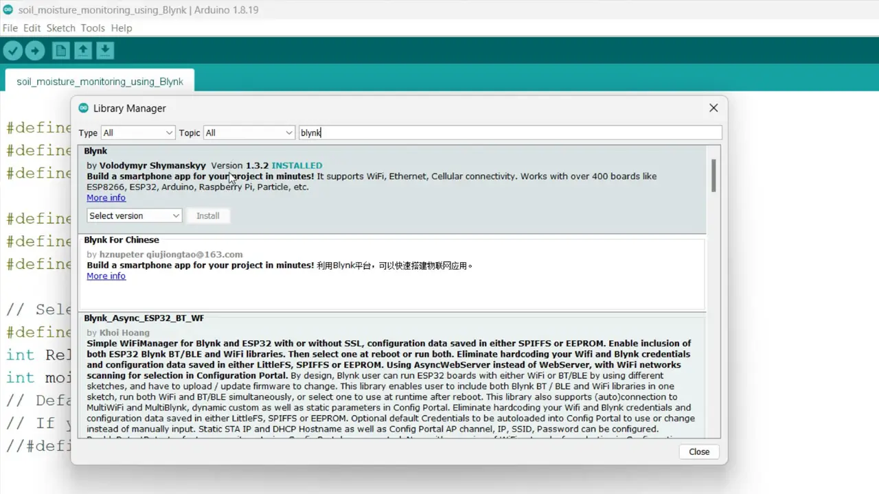
You can see I have also installed this library. It works with over 400 boards. Finally, you can upload the program, in my case I have already uploaded this program. Next, you can start with the Blynk IoT Application setup on your smartphone.
Blynk IoT App setup on Smartphone:
Open the blynk App on your smartphone and click on the “MLX sensor with ESP32 using SIM7600G”.
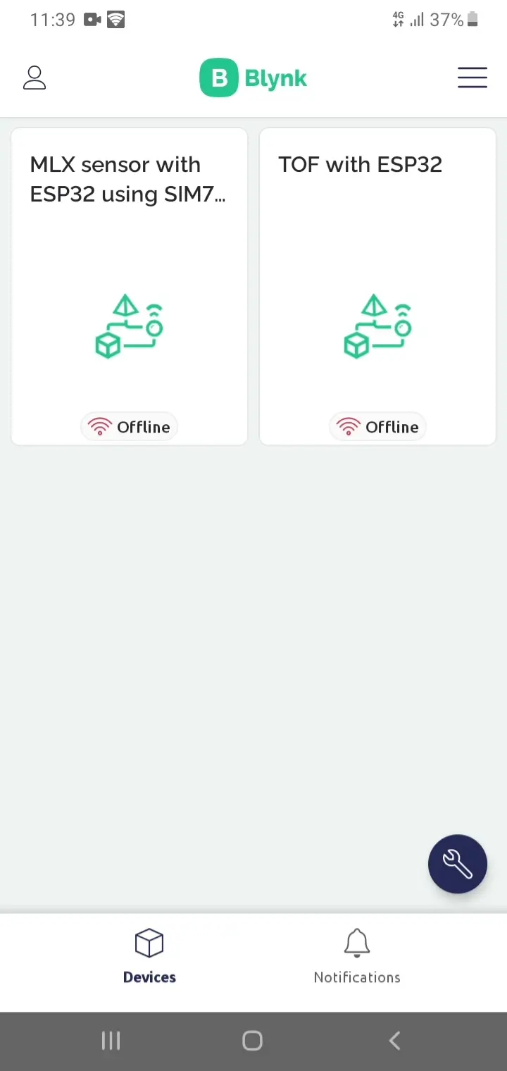
Then click on the setting button to enter to the developer mode
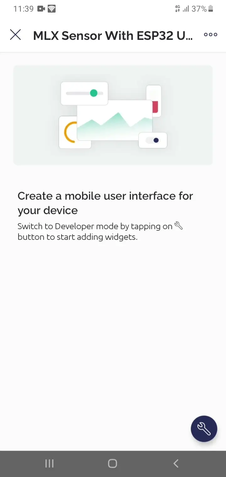
Now, you can click on the + button to add the widgets and assign the virtual variables or datastreams we created.
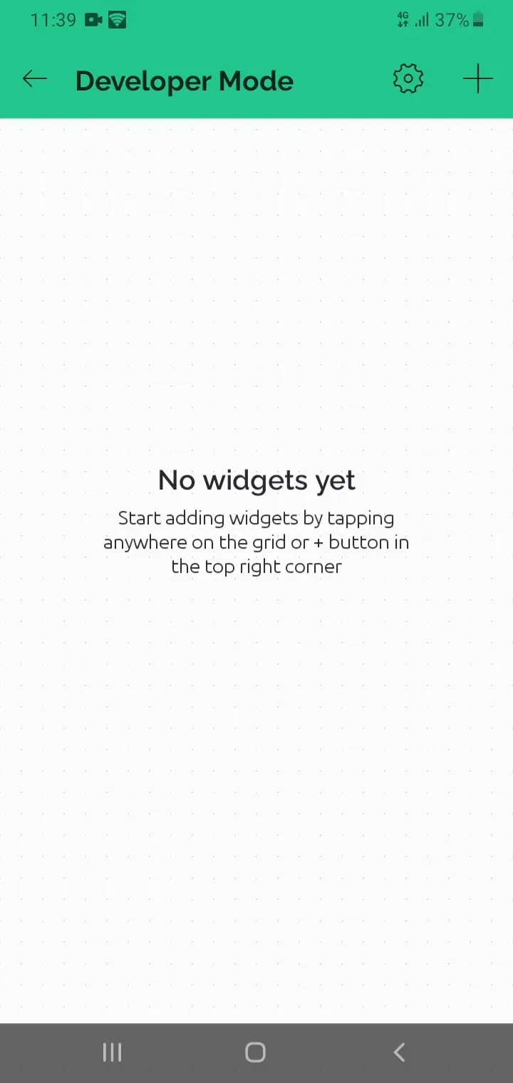
If you face any issues then you can watch video tutorial given at the end of this article.
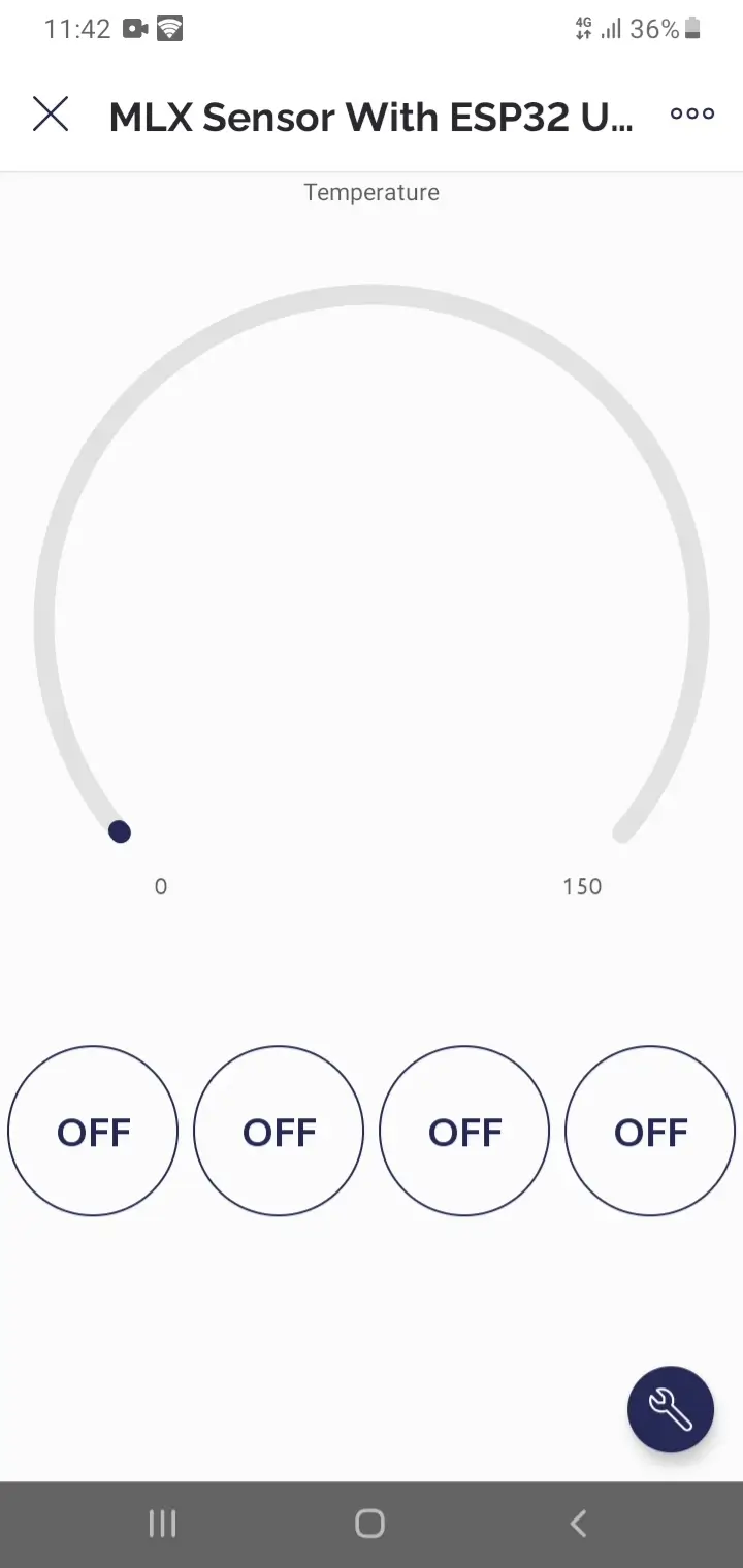
Anyway, our application is also ready, now let’s start the practical demonstration.
Practical Demonstration:
I have powered up the project using a 12V adaptor.
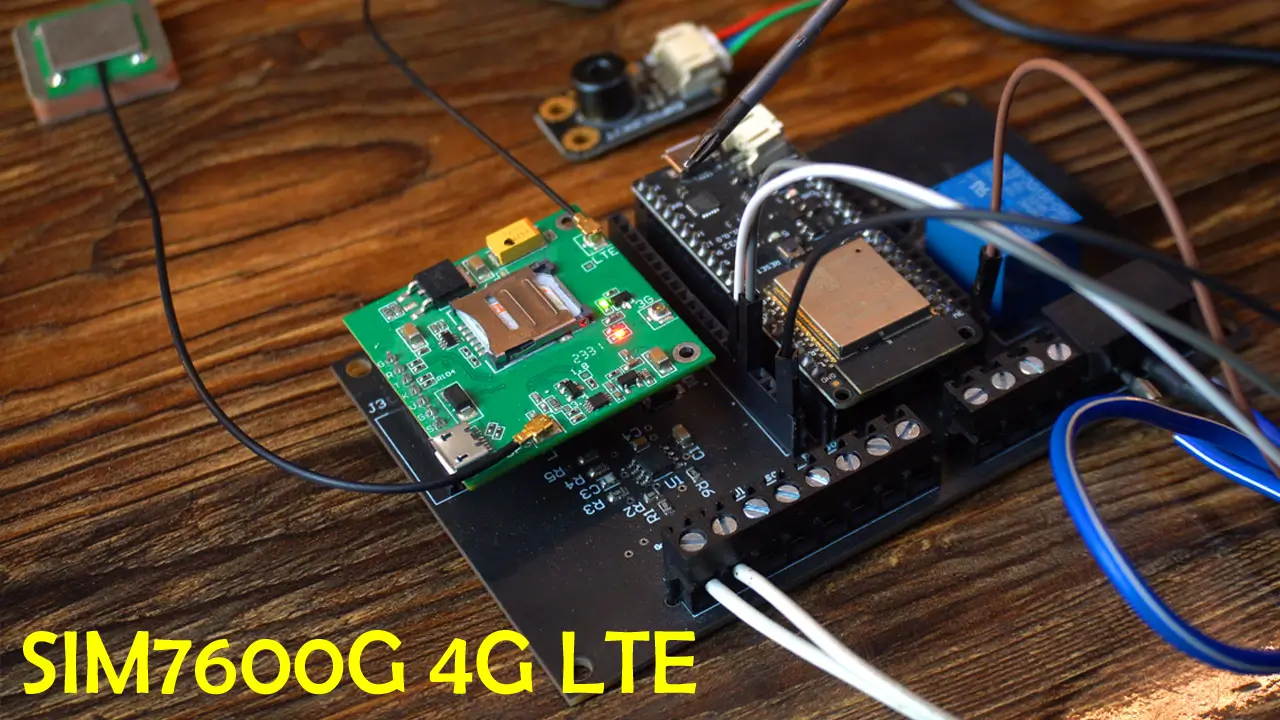
Right now, you can see it’s connected to the GSM network. In my area, the 4G network is fully functional; so, as soon as I power up this project, the SIM7600G-H immediately connects to the network. However, if the 4G network weren’t functional in my area, I could still use it because it’s also fully compatible with 3G and 2G networks.
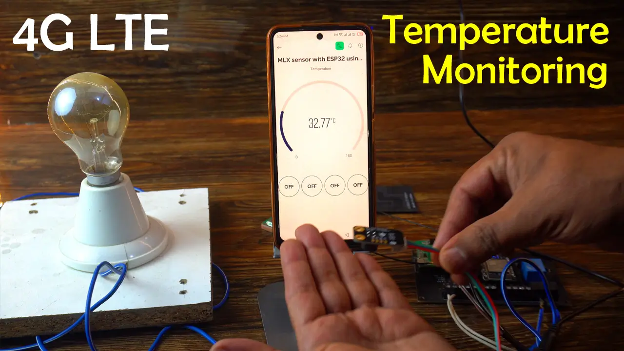
For demonstration purposes, I have connected this 110/220Vac bulb. Instead of this bulb, you can connect a motor or any other load. You can also connect a DC load. Although this load is optional, I have used it so that I can explain my point of view. For example, if the temperature increases above certain threshold value, we can use this relay to disconnect the power supply or turn off that load. I hope you understand what I’m trying to say.
Safety:
Anyway, remember, safety first: When the 110/220Vac supply is connected, never touch the relay contacts as it can be extremely dangerous. It is important to note that when working with mains voltage, proper safety precautions should always be taken, and it is advisable to consult relevant electrical codes and standards.
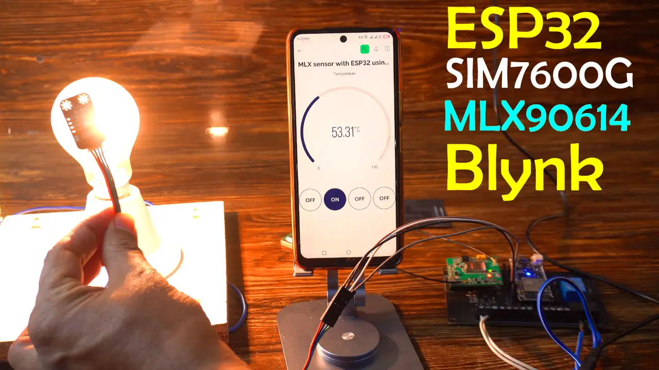
To monitor the temperature and to turn the load ON or OFF, we no longer need to write text messages. Because now, with the help of the Blynk application, we can monitor the temperature in real-time.
It doesn’t matter which country you are in; if you have internet access, you can monitor the temperature and also turn the load ON or OFF in real-time.
So, that’s all for now.
Support me on Patreon:
If you enjoy my work and find these projects helpful, please consider supporting me on Patreon. With just $1, you can get access to all project source codes, schematics, and extra resources that I share with my supporters. Your support helps me continue creating new electronics tutorials, experiments, and open projects for the community. Thank you so much for being part of this journey and for supporting my work!
Watch Video Tutorial:
Discover more from Electronic Clinic
Subscribe to get the latest posts sent to your email.