I Built the Smallest GPS Tracker; Tracks on Google Maps Satellite, No SIM Card
Last Updated on October 3, 2026 by Engr. Shahzada Fahad
Table of Contents
Description:
This is a GPS tracker I built myself. And right now, it knows exactly where I am.
Let me show you how.
This tiny screen is showing my exact location. Right now. From satellites orbiting 20,000 kilometers above the Earth.
No SIM card. No WiFi. No internet.
Now I am going to show you three versions of this tracker today. And I want to be honest with you, the first version is cool. The second version is better. But the third version?
That is my exact location, on actual satellite imagery.
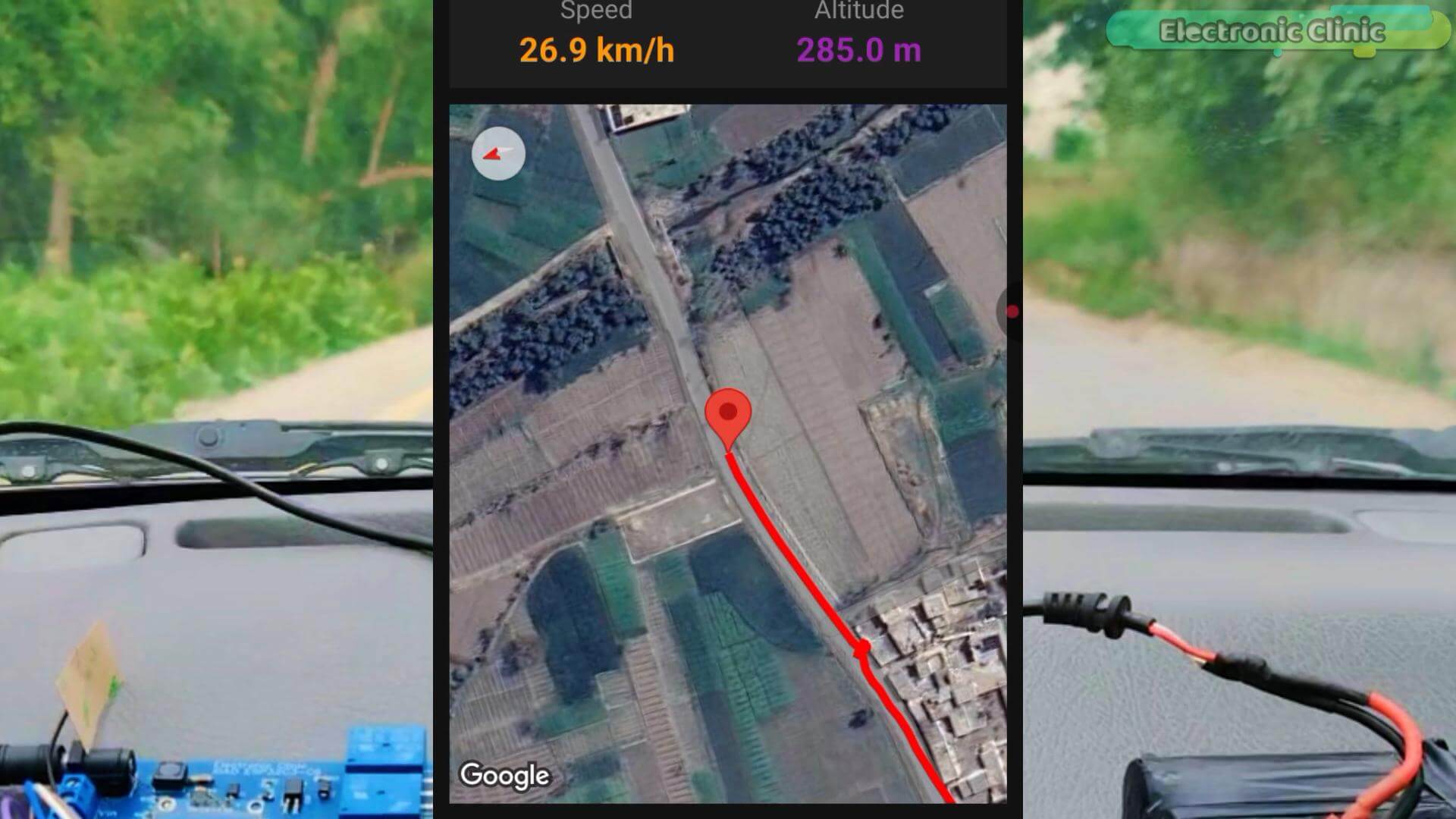
Real roads. Real buildings. Real terrain. You can see the exact road I am driving on. The exact corner I turned.

The exact rooftop I am standing on.
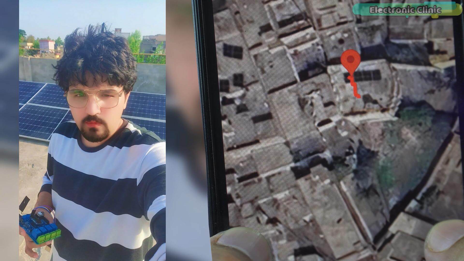
Just this.
That’s it. That’s the whole thing.
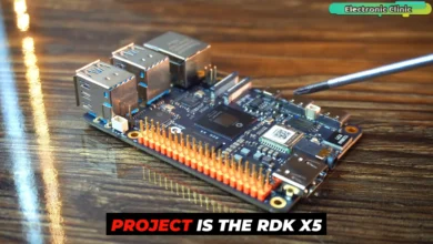
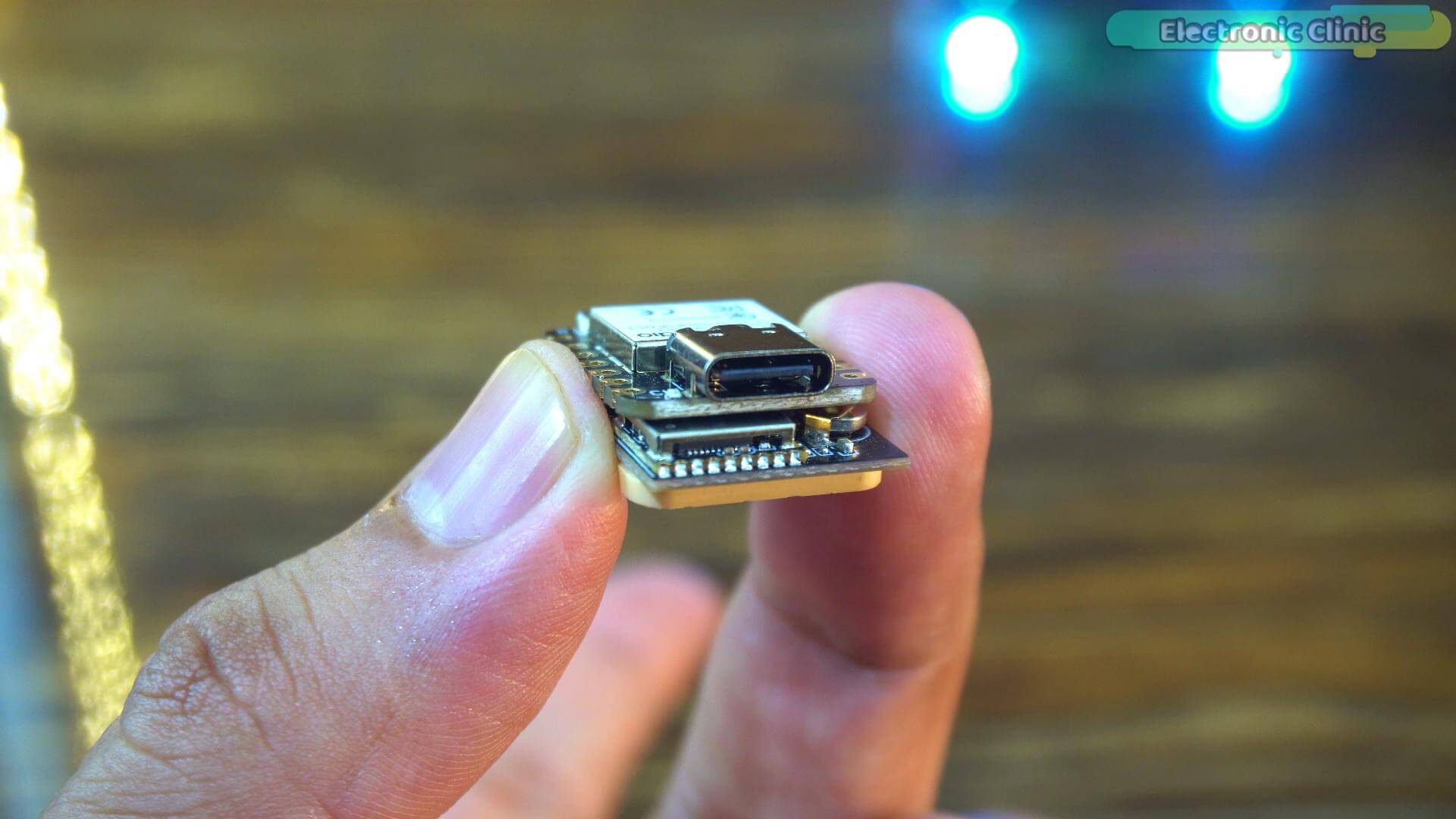
this tiny stack built it all,
But here is what I really want to show you today.
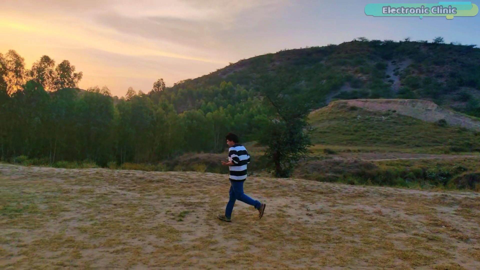
I took this thing outside. I tested it walking,
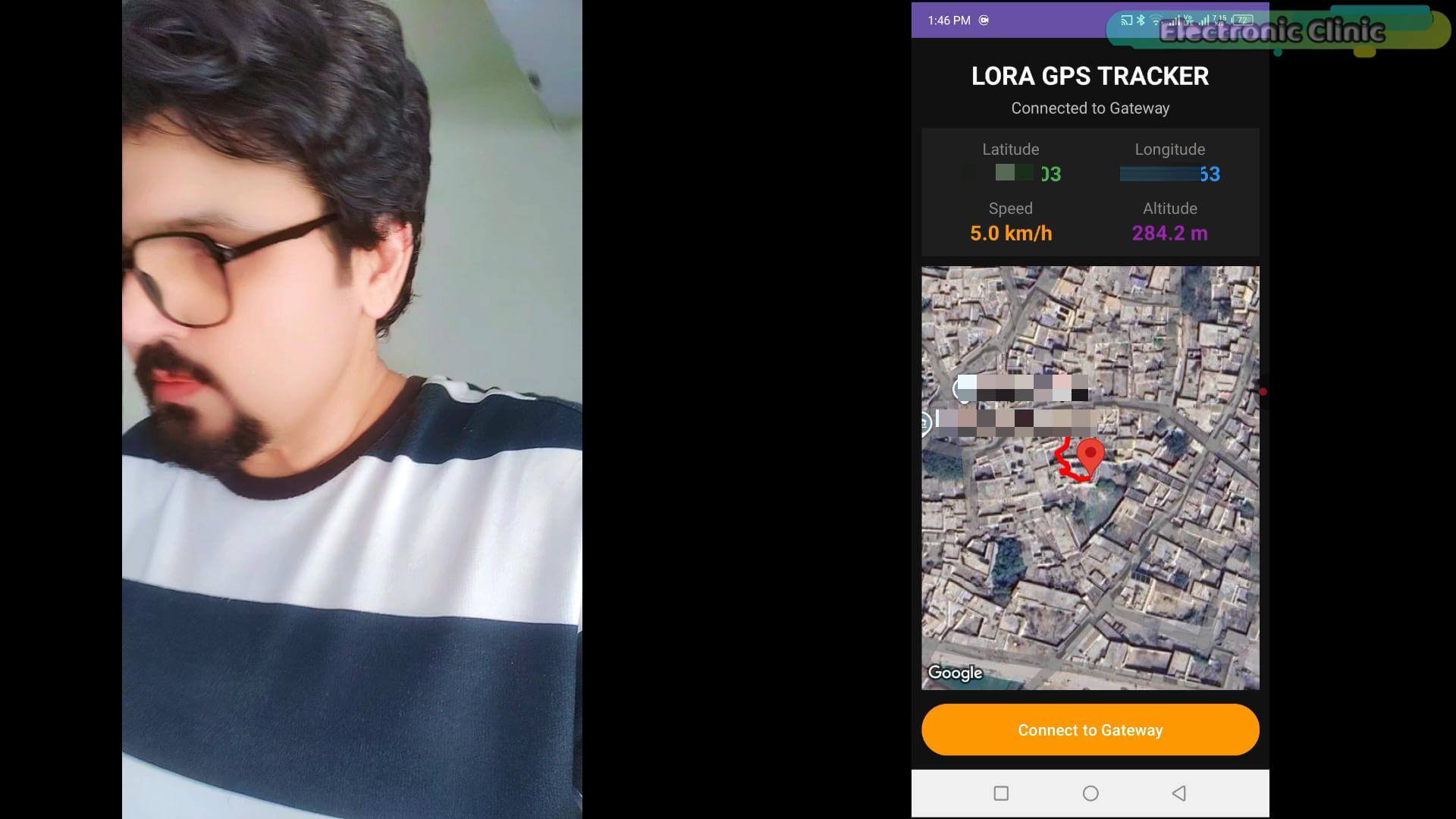
Running;
and in a moving car;
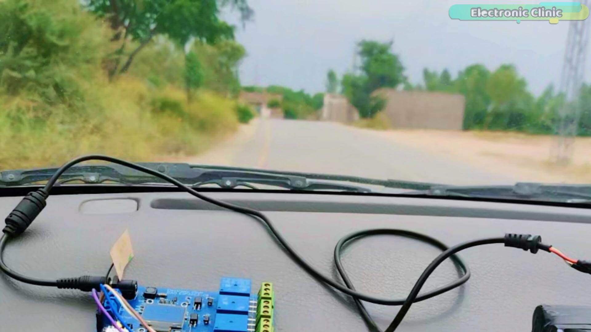
and I compared the GPS speed directly against the car’s speedometer.
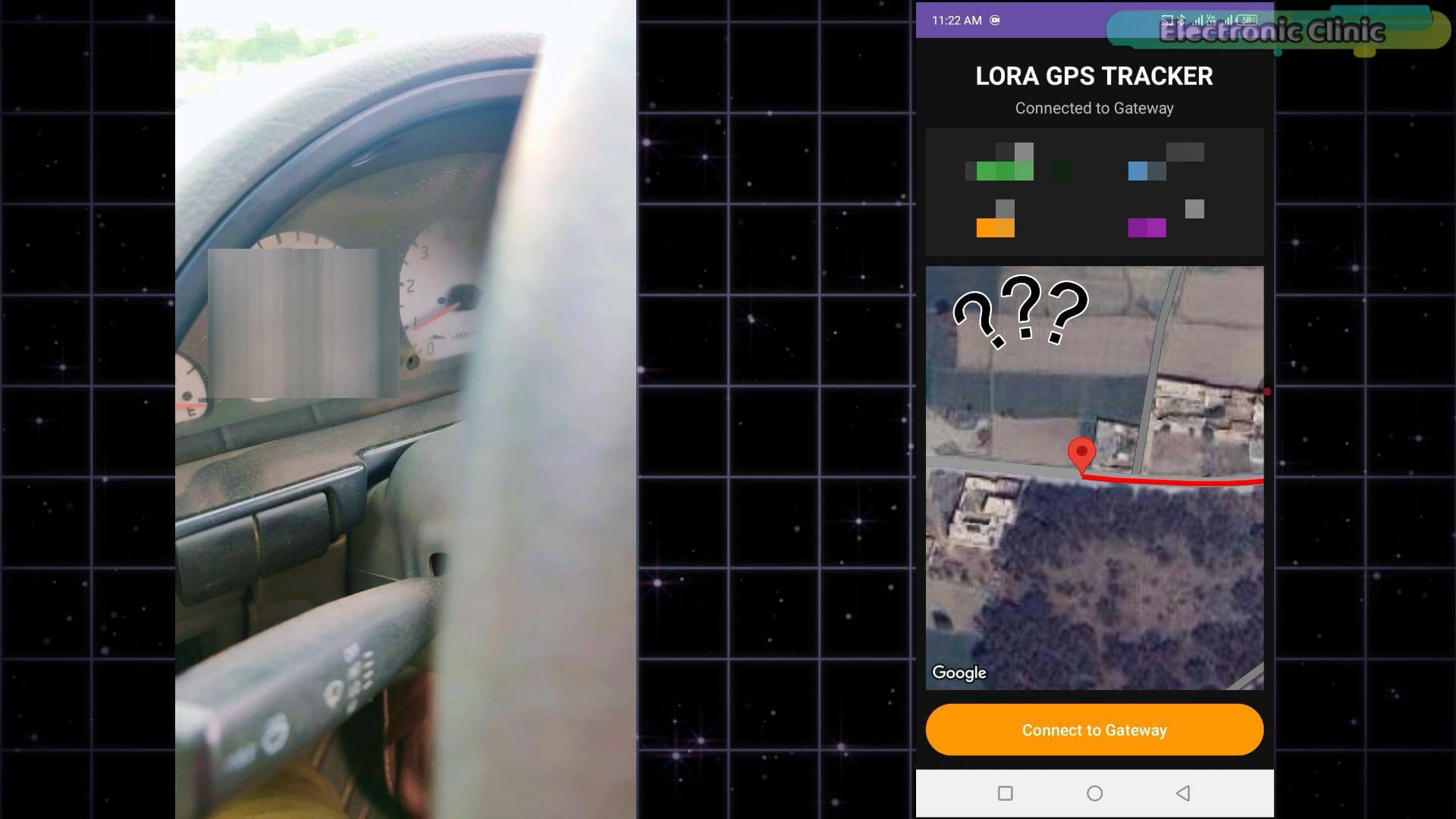
Live on camera.
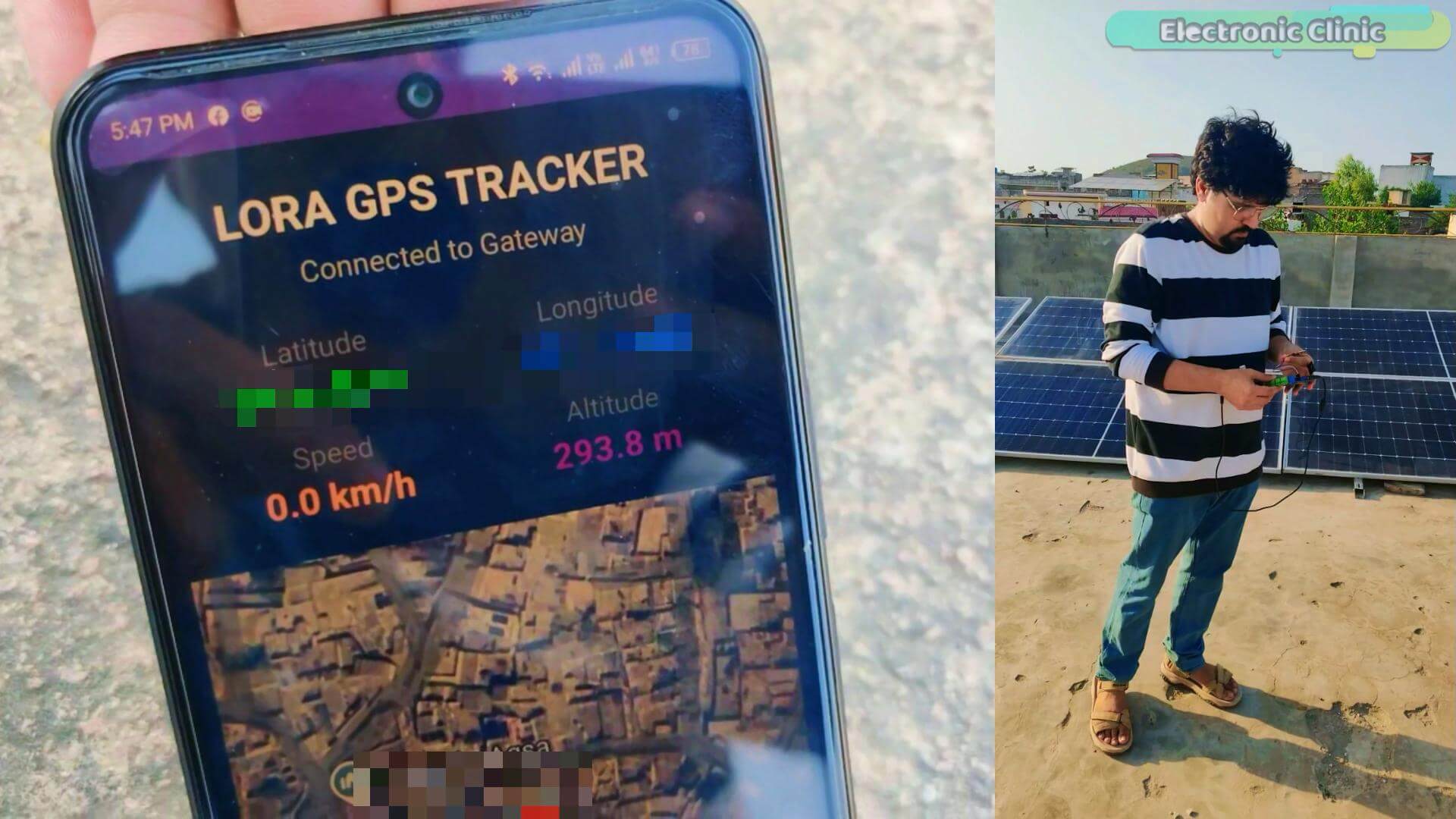
Then I took it to a rooftop for the Altitude test.
And then I thought, why stop at a rooftop?
That mountain right there is about one kilometer from my house.
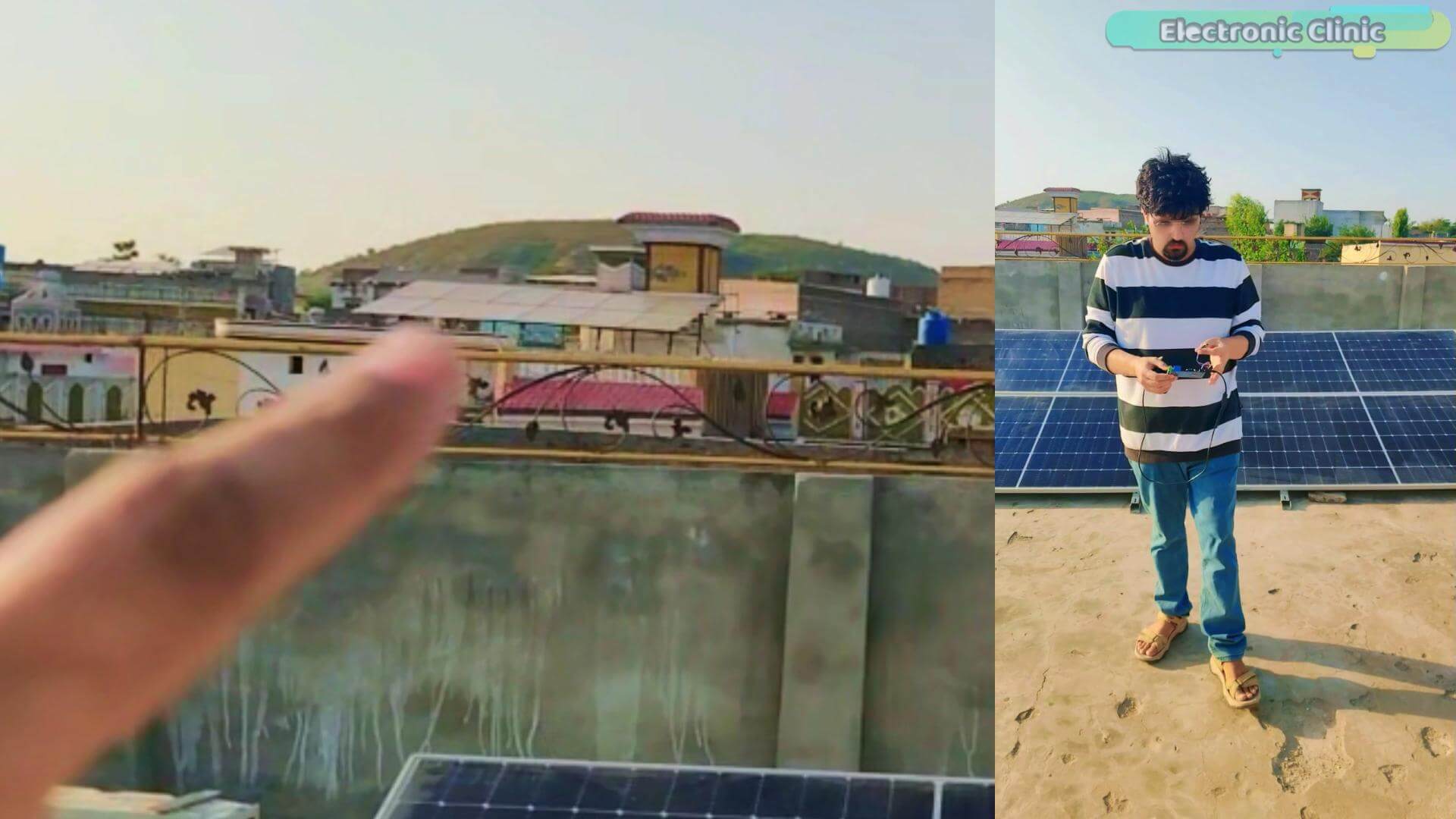
I grabbed the tracker and started making my way toward the mountain. And watched the altitude reading climb higher and higher as I made my way up.
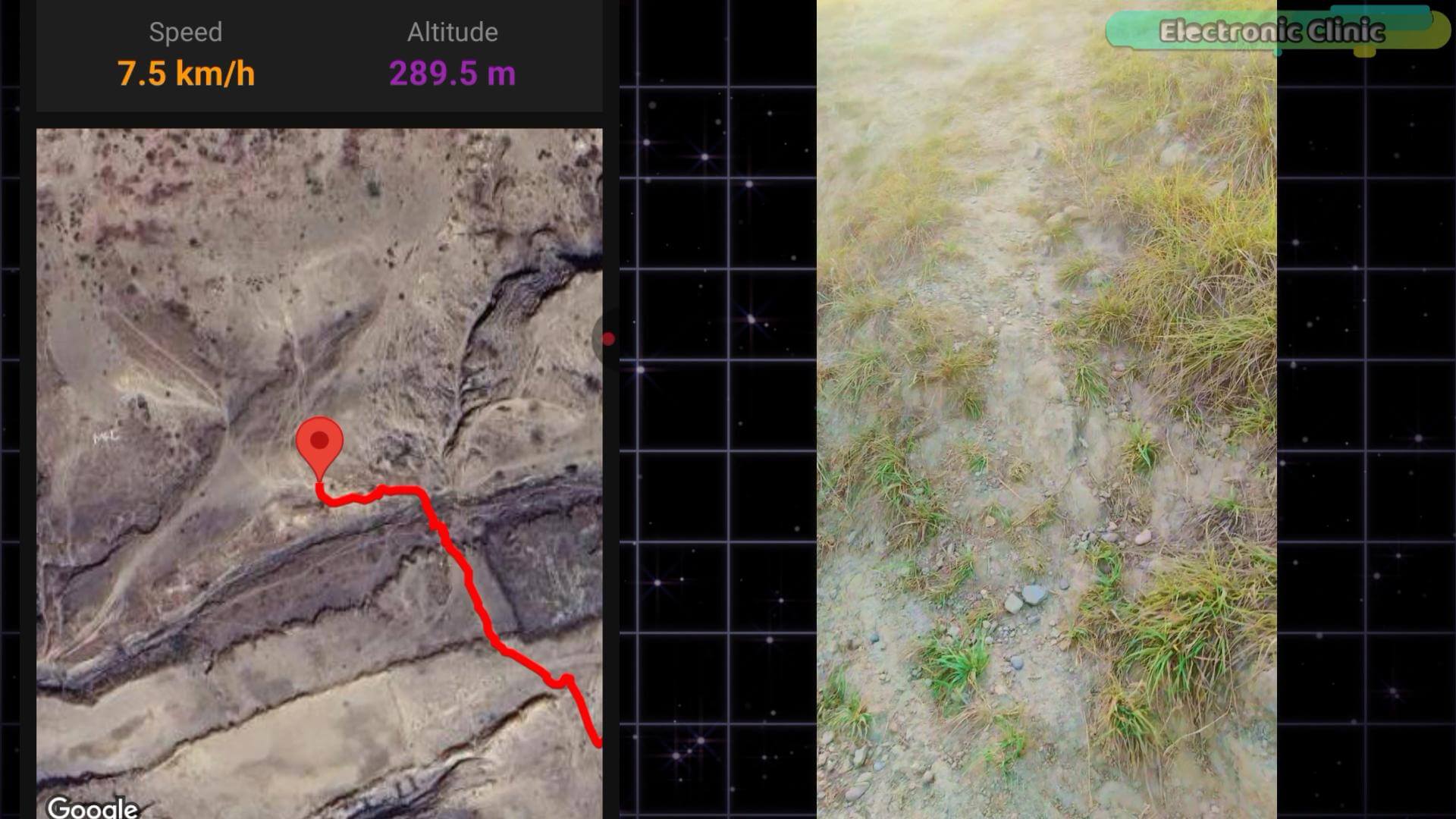
And at one point I covered the GPS antenna with a steel pot to see if I could kill the signal.
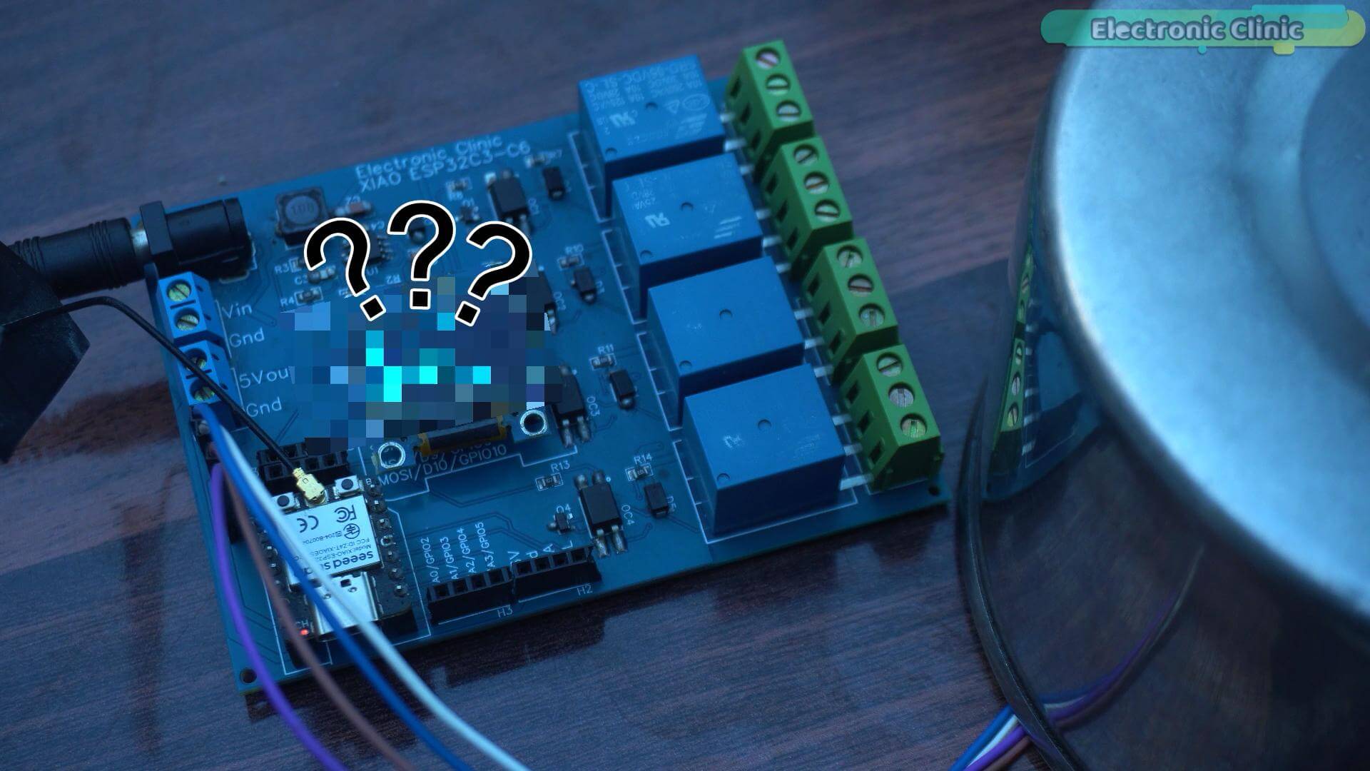
Then I flipped the antenna completely upside down; facing away from the sky entirely.
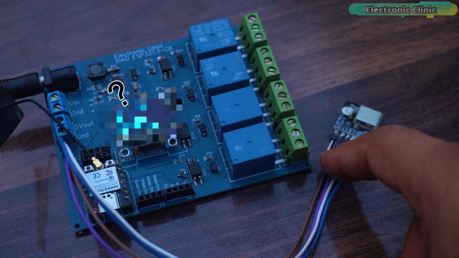
You are not going to believe what happened.
Now for all the tests in this article I will be using my own custom designed development board,
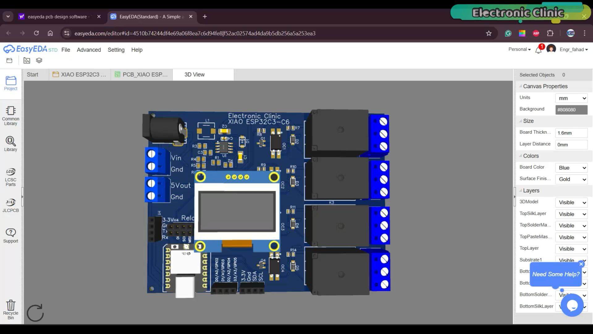
it makes everything easier to demonstrate. But the actual hardware is this small.
This is the real size.
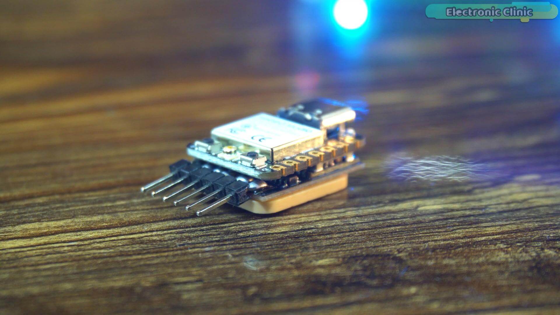
This fits in your pocket. This can go anywhere.
By the end of this article you will have a fully working GPS tracker, you will know exactly how it performs when it matters, and you will know how to connect a GPS module, read live GPS data, show it on an OLED screen, send it wirelessly to your phone, build a free tracking app, and track movement on Google Maps satellite view, and I will show you how to set up the API key, step by step.
And there are some tests coming up in this article, I am sure you don’t want to miss.
So without any further delay, let’s get started.
Amazon Links:
Other Tools and Components:
ESP32 WiFi + Bluetooth Module (Recommended)
Arduino Nano USB C type (Recommended)
*Please Note: These are affiliate links. I may make a commission if you buy the components through these links. I would appreciate your support in this way!
What We Are Building
Before we start wiring things together, let me quickly walk you through what we are actually building.
This project has three stages and each one builds on the previous.
Stage one is where we learn how GPS works. We connect the GP-02 GPS module to the XIAO ESP32-C3 and display live information on the OLED screen, coordinates, speed, altitude, satellite count. This stage is important because it lets us verify everything is working correctly before we add anything else.
Once that is confirmed, we move to stage two.
Same hardware. Same wiring. Not a single wire changes. The only difference is the software. Now instead of just showing data on the OLED, we send it wirelessly to an Android phone using Bluetooth Low Energy. Latitude, longitude, speed, altitude, all updating on your phone in real time.
And then comes stage three. This is where it gets really interesting.
We put those coordinates on a map. And I will show you two versions.
The first version is completely free; no API key, no billing account, no monthly charges; perfect if you just want to get started quickly.
The second version uses Google Maps satellite imagery, so instead of a basic map you are looking at real roads, real buildings, real terrain. The tracking experience is on a completely different level.
So whether you are building a vehicle tracker, a bike tracker, a pet tracker, or just experimenting with GPS technology; this project will give you everything you need to get started.
Let’s Talk About The Hardware
Now, let me introduce you to the three components we are using today; and more importantly, why I chose each one specifically for this project.
The SSD1306 OLED Display
Let’s start with the display.
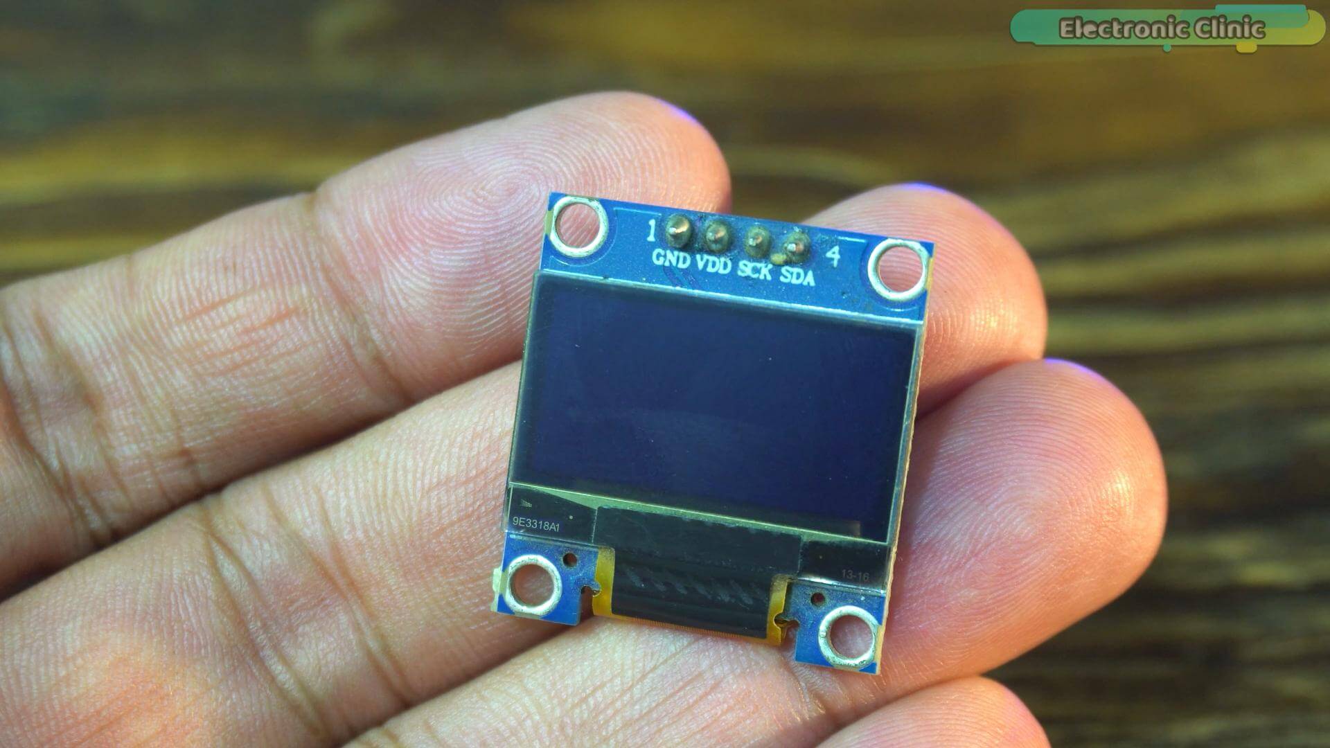
Now I know what some of you are thinking; do we really need a screen? And honestly, no. You don’t. In the later stages of this project we are going to monitor everything directly on our phone,
so the display becomes optional.
But here is why I included it anyway.
If you are a beginner, this display is your best friend. The moment your GPS locks onto satellites, you can see the coordinates, speed, altitude, and satellite count updating right in front of you;
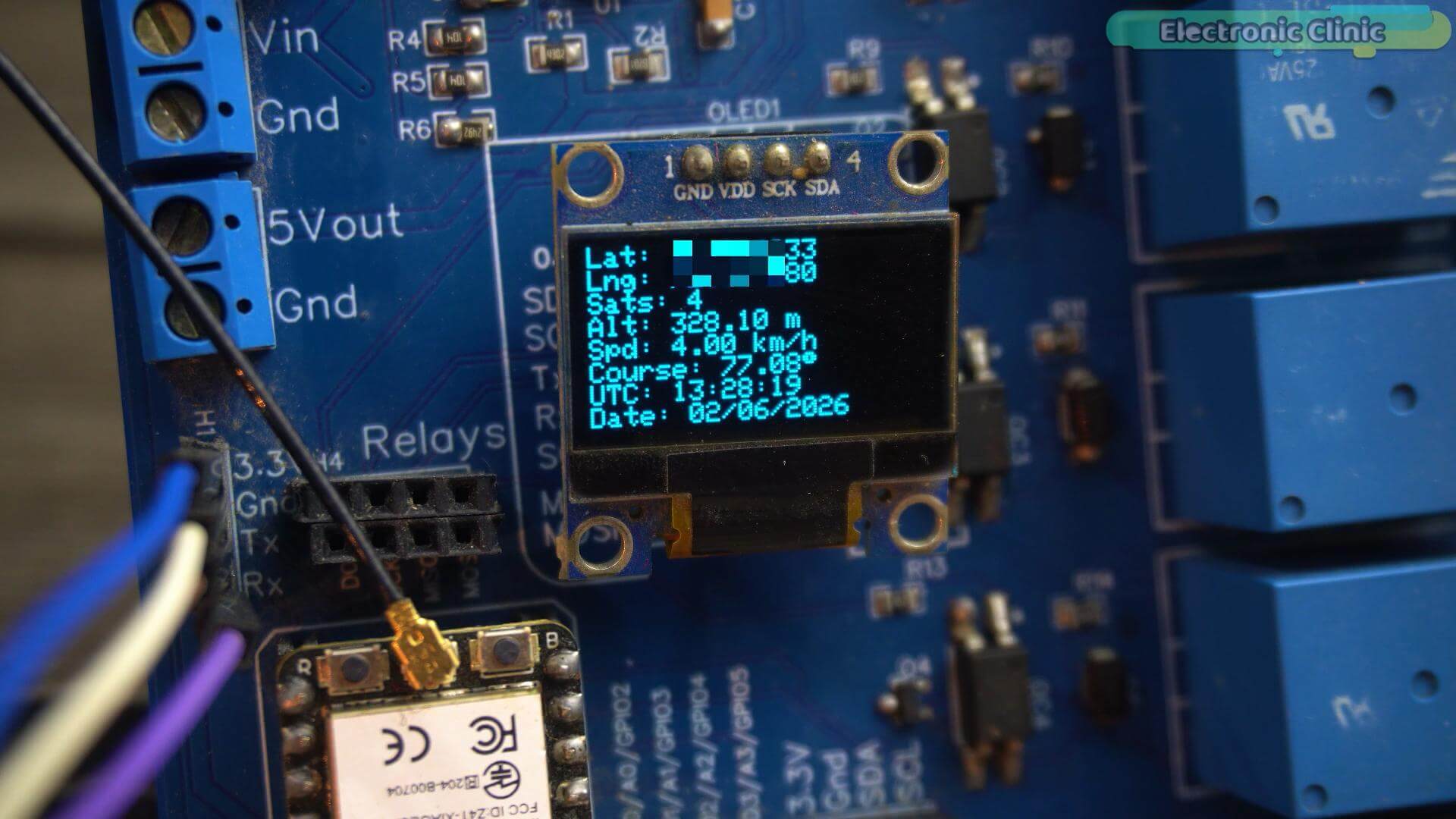
no phone, no computer, no serial monitor. Just instant visual feedback. And when something goes wrong, and trust me in electronics something always goes wrong, this display tells you exactly what is happening.
Now why the SSD1306 specifically? Why not an LCD or any other display?
Because this tiny screen is incredibly efficient. It runs on I2C which means only two data wires. It draws around 20 milliamps during normal operation; some LCD displays pull five to ten times more current than that.
But here is something important to understand. If you are building a battery powered GPS tracker that needs to run for days or even months, you actually want to remove the display completely. Any display, no matter how efficient, will drain your battery faster than you want. The OLED is perfect for what we are doing today — testing, learning, and verifying that everything works correctly. But once your project is ready and you deploy it in the real world, you switch to the phone app, ditch the display, and your battery life improves dramatically.
Think of the OLED as your development companion. It is there while you build. Gone when you deploy.
And reliability? The SSD1306 has been around for years. It works first time, every time. No flickering, no complicated initialization, no extra components. Just power it up and it works.
Small. Efficient. Reliable. Perfect for this project.
The XIAO ESP32-C3
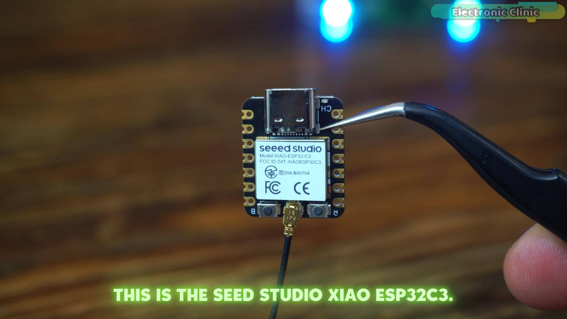
Now let’s talk about the brain of this project.
If you have been following this channel for a while, you have already seen this board in action. But every time I use it, it still impresses me, and today I want to go a little deeper into why I keep coming back to it.
This is the Seeed Studio XIAO ESP32-C3.
Look at the size of this thing. It is literally smaller than your thumb. But do not let the size fool you because what is packed inside this tiny board is genuinely impressive.
It runs on a 32-bit RISC-V processor at up to 160 MHz. It has built-in WiFi and Bluetooth Low Energy, which means for this project we don’t need any external Bluetooth module. Everything is already there, ready to go.
But here is the part I really love.
The XIAO ESP32-C3 has an onboard lithium battery charging circuit built right in. That means you can connect a small LiPo battery,
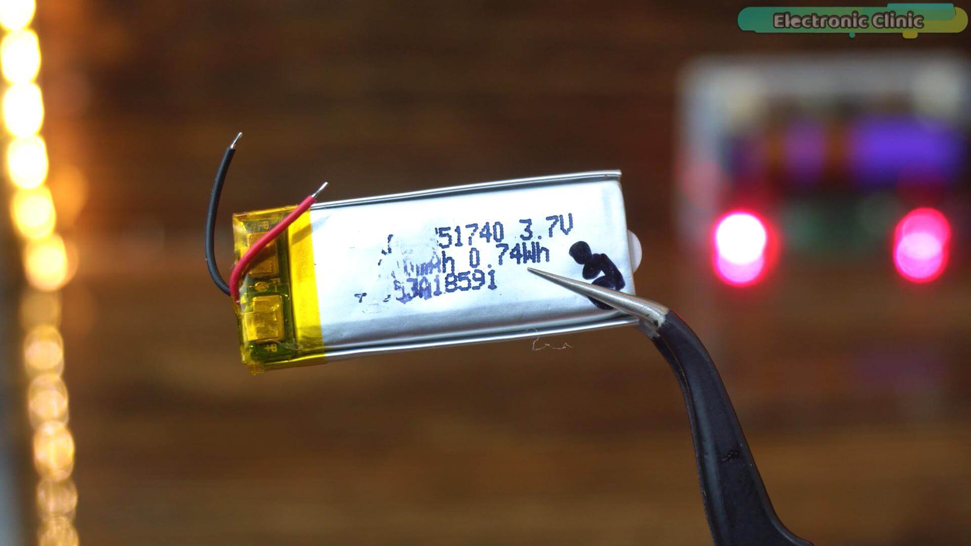
charge it through the USB-C port, and your GPS tracker becomes completely wireless. No power bank. No cables. Just a tiny self-contained tracking device that fits in your pocket.
Speaking of USB-C, yes, it has USB-C. No more fighting with micro USB cables in the dark.
And for a board this small, the number of pins and interfaces is remarkable. UART, I2C, SPI, GPIO, everything we need for this project is right there.
This is why the XIAO ESP32-C3 is one of my favorite boards right now. Small enough to hide inside any enclosure, powerful enough to handle GPS decoding, OLED updates, and Bluetooth communication all at the same time, and smart enough to charge your battery while it works.
The GP-02 GPS Module
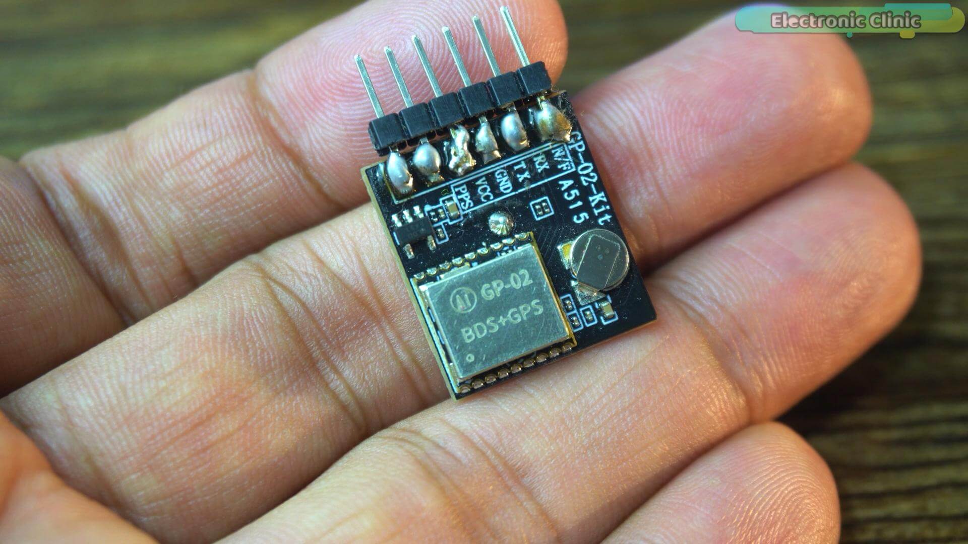
And now the star of today’s project. The GP-02 GPS module from AI-Thinker.
Now I have tested a lot of GPS modules. NEO-6M, NEO-M8N, various generic boards, and the GP-02 genuinely surprised me.
Now let me tell you something I did not expect.
I tested this module indoors. Sitting at my desk. No window. No direct view of the sky. Concrete walls on every side.
And it still locked onto satellites.
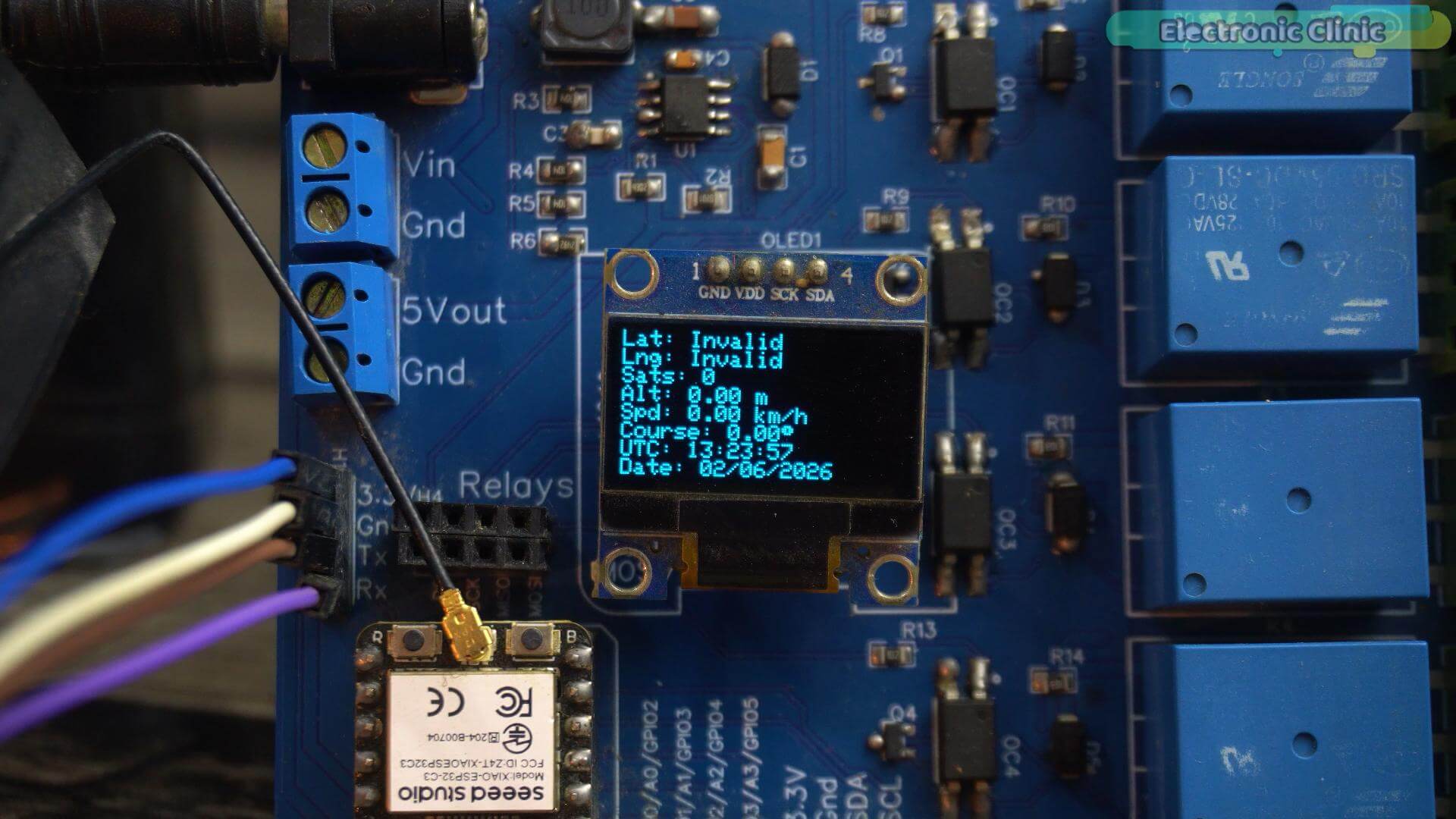
Most GPS modules in this situation? They give up. They just sit there blinking, waiting for open sky. This one kept searching. Kept trying. And eventually, it found them. Through the ceiling. Through the walls.
And the time it took? I am not going to tell you. You are going to see it for yourself in just a moment, and I promise you, the number is going to surprise you.
Then take it outside, and that result is going to surprise you even more.
Now let’s talk about what makes this module technically interesting.
The GP-02 is not just a GPS receiver. It supports multiple satellite navigation systems simultaneously; I will print these on the screen GPS from the United States, GLONASS from Russia, and BeiDou from China.
That means instead of relying on one constellation of satellites, it is talking to three. More satellites in view means faster fixes,
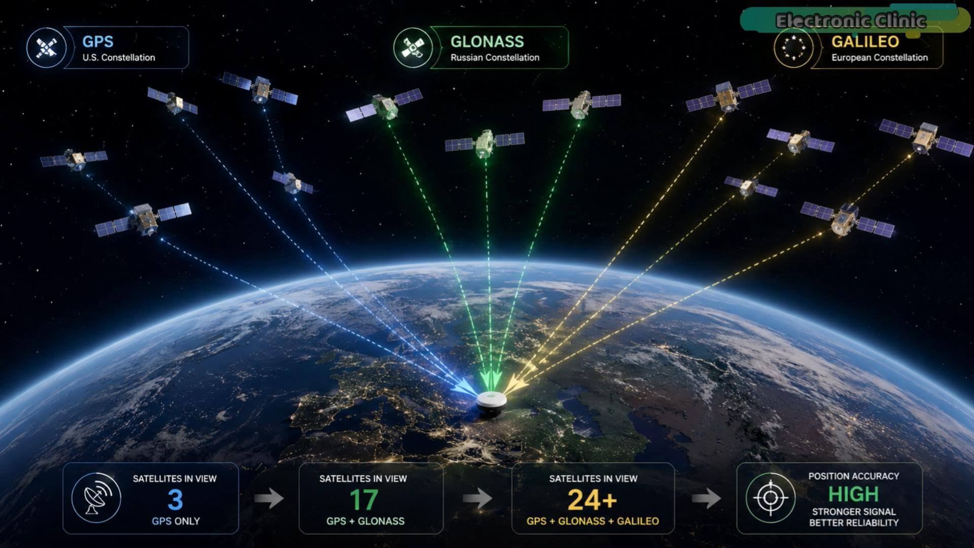
better accuracy, and more reliable performance in difficult environments like cities with tall buildings or areas with heavy tree cover.
Technical Specifications
Let me go through the most important specs directly from the datasheet, because these numbers actually tell a very interesting story.
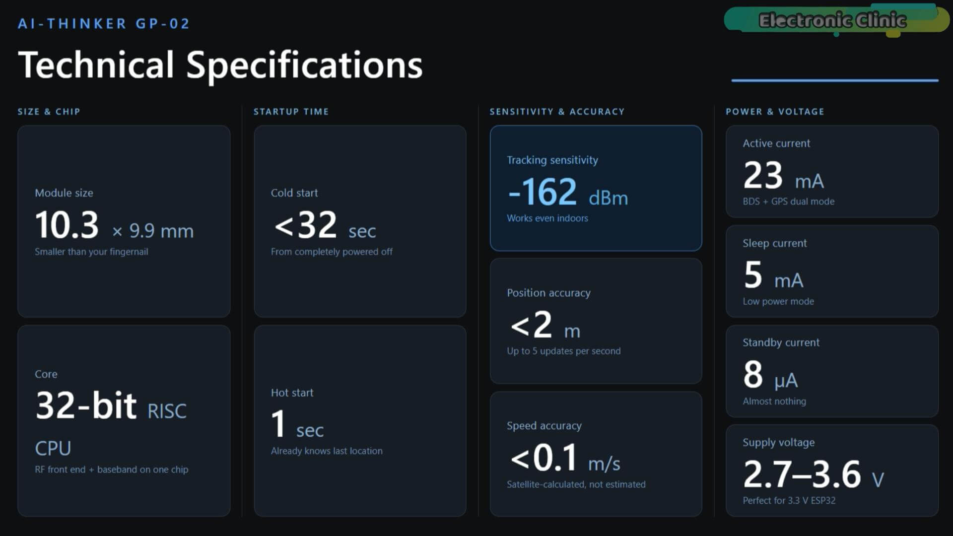
The module is tiny. Just 10.3 by 9.9 millimeters. That is smaller than your fingernail. Yet inside that tiny package is a complete RF front end, a digital baseband processor, and a 32-bit RISC CPU, all on a single chip.
Cold start time is under 32 seconds. That means from a completely powered off state, it can find satellites and get a valid position fix in under half a minute outdoors.
Hot start, meaning it already knows the approximate time and location, takes just 1 second.
Tracking sensitivity is -162 dBm. This is the number that explains why it can pick up satellites even indoors. The lower this number, the weaker the signal it can still detect. -162 dBm is extremely sensitive.
Positioning accuracy is under 2 meters.
Speed measurement accuracy is under 0.1 meters per second.
And it can update your position up to 5 times per second.
Power consumption during normal operation is 23 milliamps. In sleep mode it drops down to just 5 milliamps. And in standby it goes all the way down to 8 microamps, almost nothing.
This makes it very suitable for battery powered projects where power saving matters.
It operates between 2.7 and 3.6 volts, which pairs perfectly with the XIAO ESP32-C3 running at 3.3 volts. No level shifting required. No extra components needed.
GP-02 GPS Pinout Explained
Now let’s look at the pins on the development board because this is where beginners sometimes get confused.
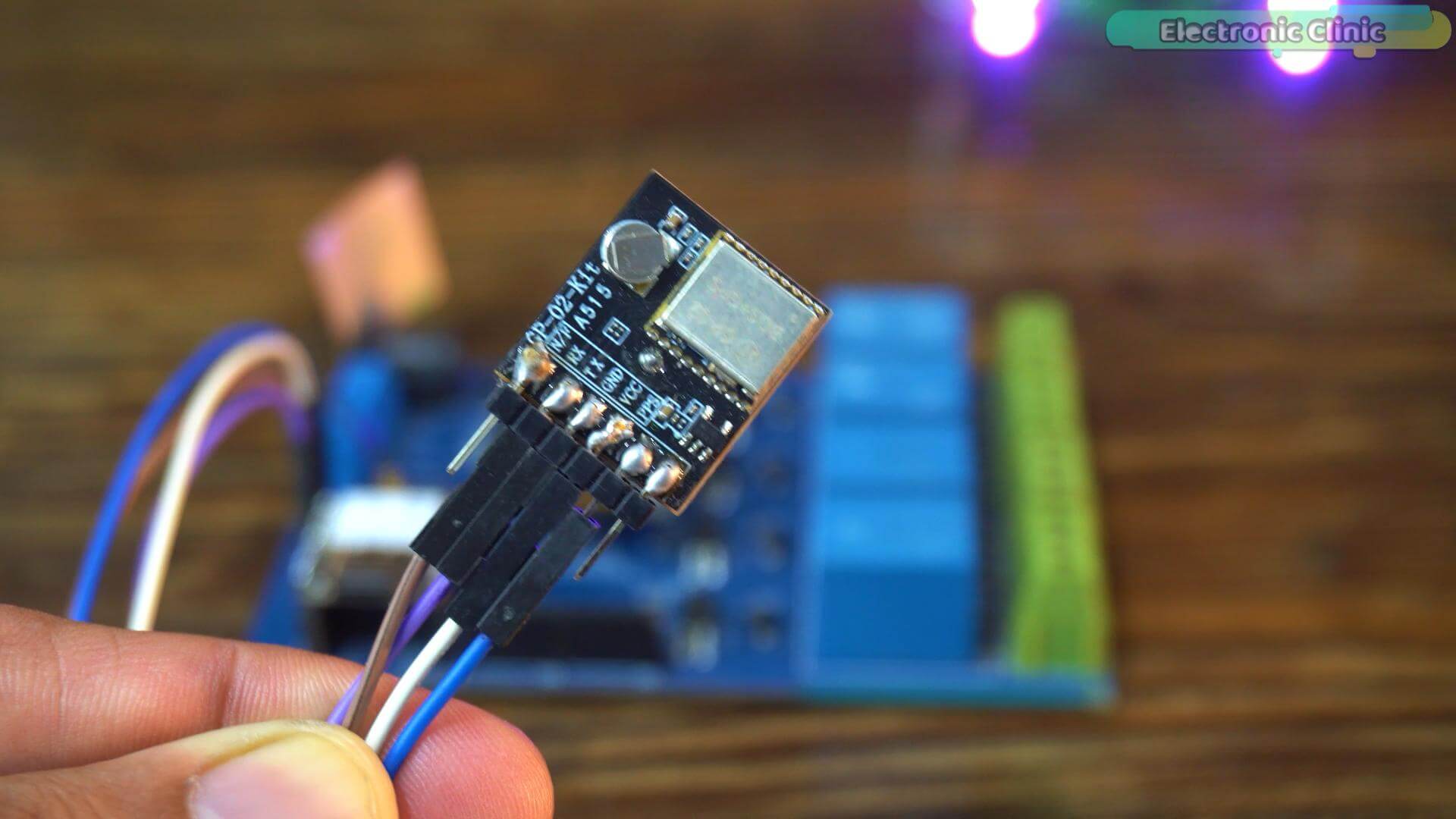
Looking at the board you can see six pins along the left side.
The first one at the top is N/F, you can ignore this one for our project, it is a shutdown control pin and it is internally pulled up so it stays active automatically.
Next is RX, this is where the module receives commands from the ESP32.
Then TX, this is where the module sends GPS data out to the ESP32.
Then GND, ground.
Then VCC, power supply, connect this to 3.3 volts.
And finally PPS, this stands for Pulse Per Second. It sends out one precise pulse every second synchronized to GPS time. We are not using this in our project but it is incredibly useful for timing applications.
The most important thing to remember is RX and TX. A lot of beginners get this wrong. The TX of the GPS must connect to the RX of the ESP32. And the RX of the GPS must connect to the TX of the ESP32. Think of it like a conversation, the talker connects to the listener. Mix these up and you will get no data at all.
That Little Battery On The Board
Now you might have noticed this small component on the board.
That is a backup battery.
Here is why it matters. Every time you power up a GPS module from scratch it needs to do what is called a cold start, it has no idea where it is, what time it is, or which satellites are overhead. That takes up to 32 seconds outdoors.
But when this backup battery is connected and keeps a tiny amount of power flowing to the module’s internal memory, it remembers the last known time, location, and satellite positions. The next time you power it up it does a hot start instead, and that takes just 2 to 3 second.
So that tiny battery is the reason your GPS tracker locks onto satellites almost instantly after the first use. It is a small detail that makes a huge difference in real world performance.
Another reason I selected this module is because it works perfectly with compact boards like the XIAO ESP32-C3.
Imagine building:
Vehicle tracking systems
Bicycle tracking systems
Wildlife monitoring systems
Portable navigation tools
Hiking trackers
The GP-02 fits all of these applications.
Small module. Multi-constellation support. Incredible sensitivity. Built-in memory backup. Works indoors.
This is exactly what a compact GPS project needs.
Now that you know what each component brings to the table, let’s connect everything together.
WIRING EXPLANATION
Now let’s connect everything; and I want you to pay attention here because getting the wiring right is the difference between a working project and hours of frustration.
This is actually one of the simplest wiring setups I have ever done for a GPS project.
And the best part? These connections stay exactly the same for all three versions in this article.
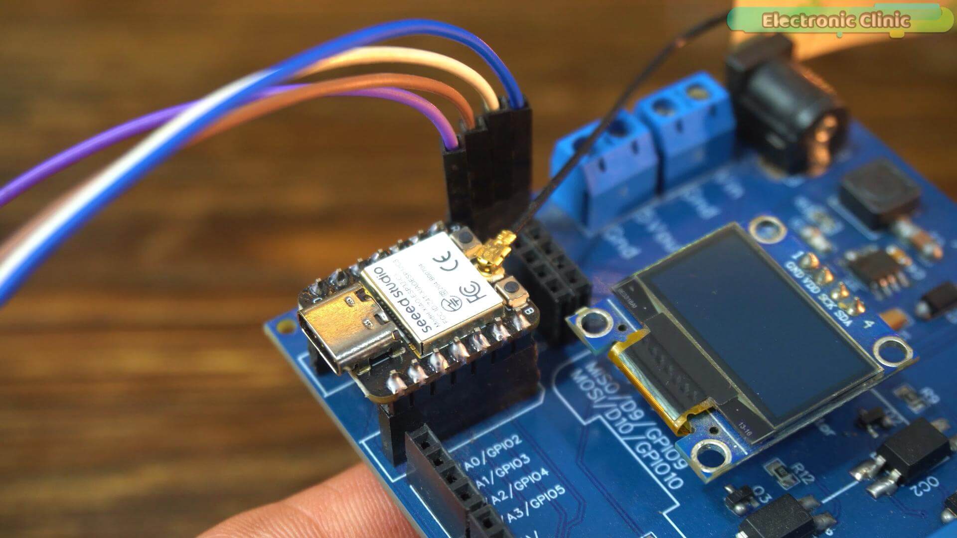
Whether we are displaying data on the OLED, sending it wirelessly to a phone, or tracking on a satellite map, not a single wire changes. You wire it once and you are done.
Let’s start with the OLED display.
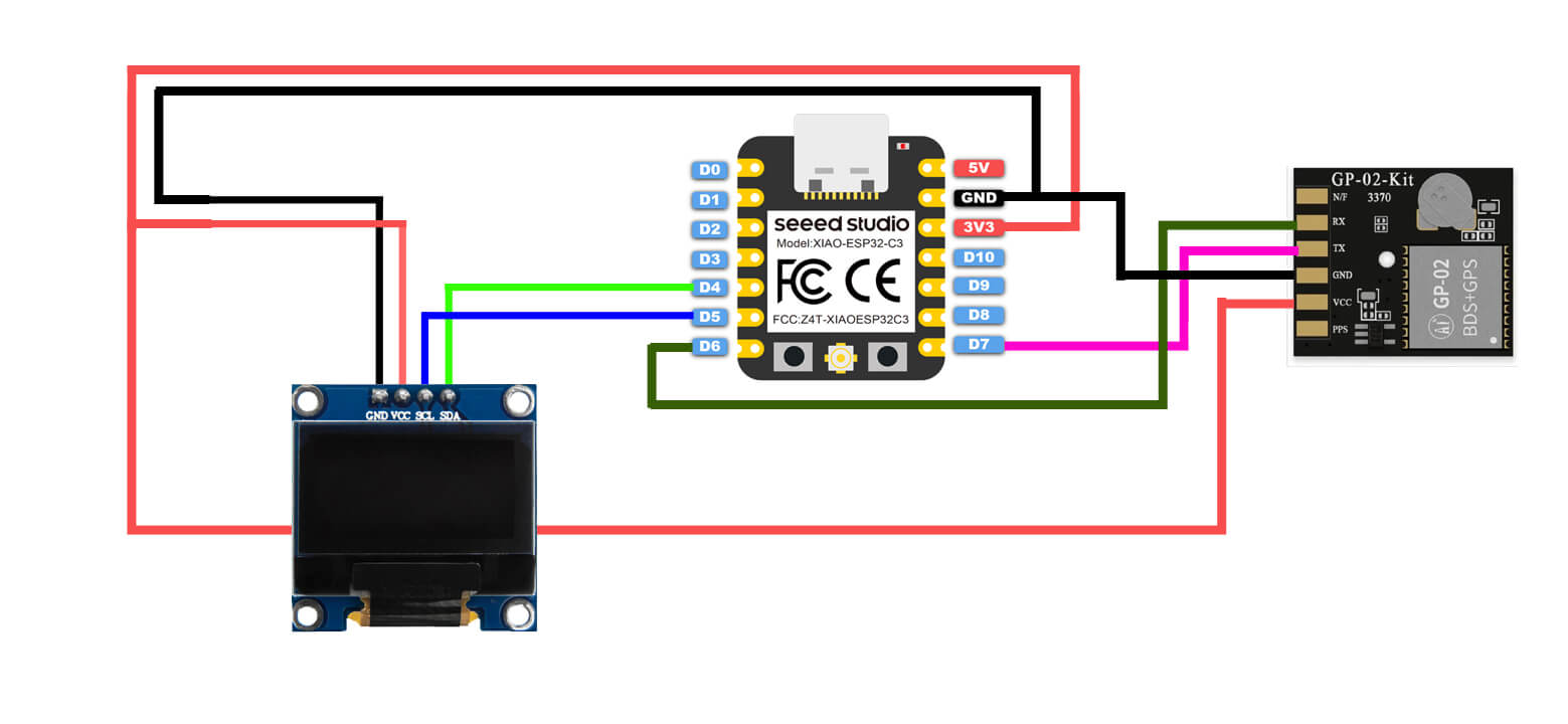
It uses I2C communication which means only four wires.
Connect VCC to 3.3 volts. GND to GND. SDA to D4. And SCL to D5. That’s it. Four wires and your display is ready.
Now let’s connect the GPS module. This one uses UART communication; also four wires.
Connect VCC to 3.3 volts. GND to GND. GPS TX to D7. And GPS RX to D6.
Now this is where a lot of beginners make a mistake and then spend an hour wondering why they are getting no GPS data.
TX and RX must cross over.
The TX of the GPS connects to the RX of the ESP32. And the RX of the GPS connects to the TX of the ESP32. Think of it like a conversation between two people, the one who is talking must connect to the one who is listening. If both try to talk to each other at the same time nothing gets heard.
Take a moment right now to compare your wiring with the diagram on screen. One wrong connection is all it takes to get no output at all. Double check before you move on; it will save you a lot of time.
GPS Information on Oled Display:
Now before anything else, let me show you the exact setup I am using so you can match it on your end.
I am using Arduino IDE version 2.3.6. And the ESP32 board package version 2.0.11.
Make sure you are on these versions; different versions can sometimes cause unexpected issues and I want to save you that headache.
Now you will also need to install a few libraries. Let me show you exactly how.
Simply copy the library name, open the library manager in Arduino IDE, paste the name in the search box, and install it. You can see I already have this installed. Go ahead and repeat the same steps for each library.
include <TinyGPSPlus.h>
This one line is doing an enormous amount of work behind the scenes.
GPS modules don’t send you nice clean numbers. They send raw NMEA sentences, long strings of text that look something like this:
$GPRMC,123519,A,4807.038,N,01131.000,E,022.4,084.4,230394,003.1,W
Not exactly easy to work with, right?
TinyGPSPlus gps;
TinyGPSPlus takes all of that raw data and converts it into simple values we can actually use. Latitude, longitude, speed, altitude, date, time; all extracted automatically. Without this library we would have to decode every NMEA sentence manually. Trust me, that is not something you want to do.
#define gpsSerial Serial1
#define RX_PIN D7
#define TX_PIN D6
These three lines give names to the things we are about to use. We are naming our GPS serial port “gpsSerial”, and we are defining which physical pins on the XIAO ESP32-C3 will handle the GPS communication. D7 is our receive pin, this is where the ESP32 listens for incoming GPS data. D6 is our transmit pin, this is where it can send commands back to the GPS module if needed.
gpsSerial.begin(9600, SERIAL_8N1, RX_PIN, TX_PIN);
This line starts the serial connection to the GPS module. 9600 is the baud rate; basically the speed at which data is exchanged; and this matches the default speed of the GP-02 module exactly. SERIAL_8N1 means 8 data bits, no parity, 1 stop bit; which is the standard communication format.
Now here is something worth highlighting. We are using Serial1 which is the hardware UART built directly into the XIAO ESP32-C3. Hardware UART runs independently inside the chip, handles incoming data reliably, and doesn’t slow down your main program. Some boards use software serial instead, which is much less reliable especially when GPS data is arriving continuously. With hardware UART we simply don’t have that problem.
while (gpsSerial.available() > 0)
{
if (gps.encode(gpsSerial.read()))
{
displayLocationInfo();
}
}
This is the heart of the program. This loop runs continuously, reading every character that arrives from the GPS module and feeding it into TinyGPSPlus one byte at a time.
When TinyGPSPlus has received enough characters to form a complete GPS message, it decodes everything and updates all the values; latitude, longitude, speed, altitude, date, time; all at once. Then we call displayLocationInfo() to refresh the OLED screen.
Simple, clean, and very efficient.
if (gps.location.isValid())
{
display.println(gps.location.lat(), 6);
}
This is a small line of code that makes a huge difference.
When you first power up a GPS module it doesn’t instantly know where it is. It needs time to lock onto satellites. During that time it may send out data, but that data is invalid. Without this check you would display garbage coordinates on your screen and think something was broken — when actually everything is working perfectly fine.
This single check says, only show the coordinates if we actually have a confirmed satellite fix. Otherwise show “Invalid”. Clean, reliable, and professional.
display.print(gps.speed.kmph());
display.print(gps.altitude.meters());
display.println(gps.satellites.value());
gps.time.hour() / gps.time.minute() / gps.time.second()
gps.date.day() / gps.date.month() / gps.date.year()
Coordinates are just the beginning. The GP-02 gives us much more.
Speed is calculated directly from satellite positioning data, not estimated. This makes it accurate enough for bike trackers, vehicle trackers, and fitness projects.
Altitude gives us height above sea level, calculated entirely from satellite signals. No barometer, no additional sensors needed.
Satellite count is one of the most useful values to monitor. More satellites means better accuracy and more stable coordinates. It instantly tells you how healthy your GPS connection is at any given moment.
And date and time, this one surprises most beginners. GPS satellites carry atomic clock signals which mean*s the GP-02 is also giving us extremely accurate UTC time and date completely for free. No internet, no NTP server, no extra RTC module required. Very useful for data logging and IoT projects.
Now we understand exactly what the code is doing. Let’s go ahead and upload the program.
Uploading the Code:
The code has been successfully uploaded.
Now the board is completely off at the moment. Before I power it up, let me show you the three different ways you can power this project; because this is actually an important decision depending on what you want to do with it.
Option one. Just connect it to your laptop using a USB cable. Done. No extra hardware needed.
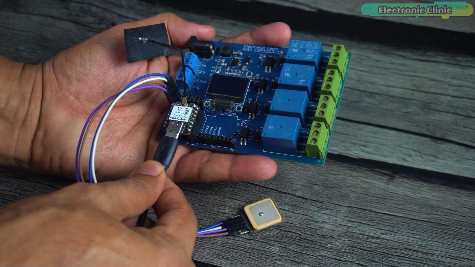
Option two; a small LiPo battery. The XIAO ESP32-C3 has dedicated battery pads on the bottom of the board.
You can solder a LiPo battery directly to those pads and the board will charge it automatically through USB. This is perfect if you want a compact portable tracker.
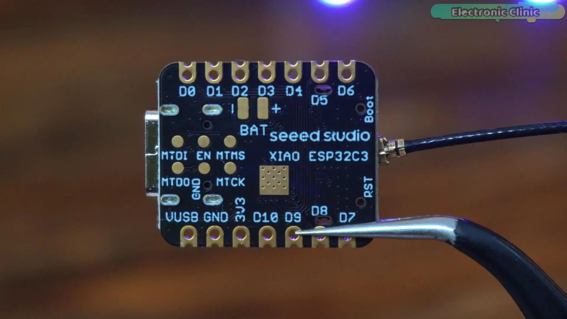
Option three; and this is what I am going to use for all the tests today. My custom designed development board has an onboard 5V 3A power supply that can accept input voltages all the way from 9 volts up to 28 volts. That means I can connect almost any battery pack or DC adapter to it.
And since I am going to be doing a lot of outdoor tests today, I am going to power it using my 4S lithium ion battery pack.
This makes the entire setup completely portable, no cables, no laptop, no power bank. Just the tracker and a battery. Exactly how a real GPS tracker should work.
Alright, let’s power it up.
Indoor Satellite Lock Test
The board is now powered up and we are indoors.
We are on the first floor, with only the rooftop above us. There are no windows and no direct view of the sky. This is the first real test; and I want to be completely honest with you about what happened here.
The moment it powers up, Lat Invalid, Lng Invalid, zero satellites, time showing 00:00:00. The module has absolutely no idea where it is. It is scanning through the ceiling, through the walls, trying to find any satellite signal it can.
Now look at this. The coordinates are still invalid and the satellite count is still zero, but something interesting just happened. The UTC time just appeared 13:23:26.
The module picked up the time signal from satellites before it could calculate a position fix. That means it is already receiving satellite signals, it just needs more of them to calculate a location.
Still searching. Coordinates still invalid. But the module is not giving up.
Great, we also got the date. This is that -162 dBm tracking sensitivity we talked about earlier actually doing its job.
There it is. We have a fix. Indoors. You can see the Latitude, Longitude, four satellites, Altitude, Speed, and Course. From the first signal to a full valid fix; it took around 3 minutes which is quite impressive.
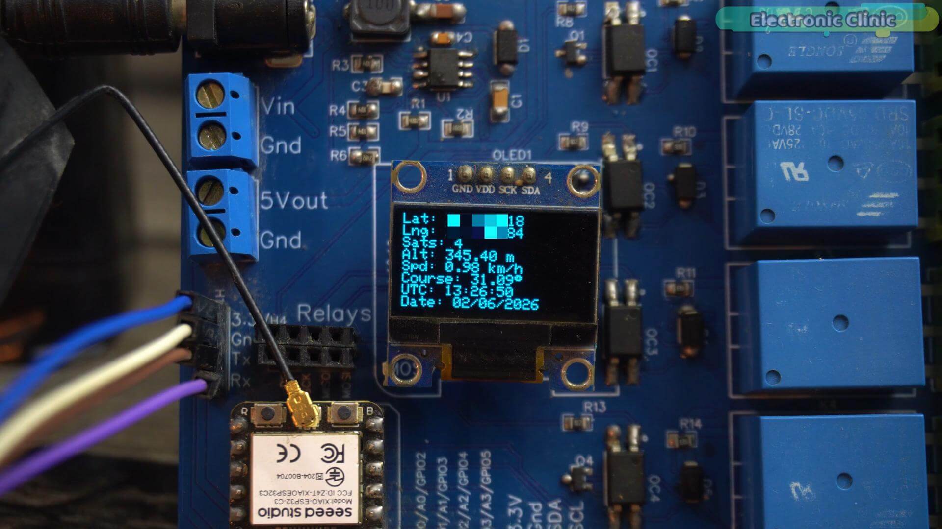
I left it running for a few more minutes, and the satellite count increased to five. That’s a good sign. The longer the module stays locked onto satellite signals, the more data it can collect, allowing it to improve the quality of the position fix. And remember, we are still indoors with no direct view of the sky. That’s pretty impressive.
Now let’s see what happens when we take it outside.
Outdoor Satellite Lock Test
I am going to power cycle the board completely; so it starts from scratch with no memory of the previous fix.
We are outside now, Board is back on… And already, UTC time and date appeared within two seconds.
Now let’s wait and see how quickly it locks onto satellites. And I want to pay attention to something specific; how many satellites does it actually connect to when we are outdoors? Because indoors we peaked at five. Let’s see what happens out here.
Notice the difference? That is significantly faster than indoors.
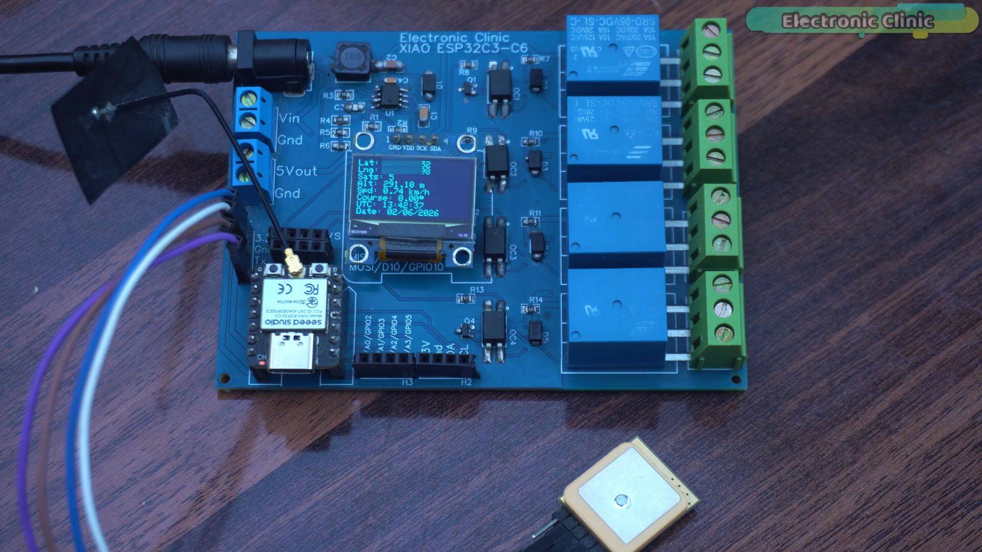
We already have a valid fix. Coordinates are showing, five satellites locked, everything stable.
And you know why it connected so fast? Because that tiny backup battery I mentioned earlier; it remembered the last known time, location, and satellite positions. That is the hot start in action. If you missed that explanation, go back and watch it because it is worth understanding.
Let’s give it a few more seconds.
And look at that; the satellite count is already climbing. This is exactly what I wanted to see. More satellites means higher accuracy, more stable coordinates, better performance. And it is still increasing, 14 satellites. This is crazy.
I waited a few more seconds and the count jumped to 16.
And then I decided to give it a little more time; and guess what. Nineteen satellites. Nineteen. I don’t even know what to say. That is insane.
This is the difference between indoor and outdoor GPS performance. Outdoors this module is fast, reliable, and accurate. Indoors it will eventually get there, but give it time.
Antenna Blocking Test
Alright, satellites are sitting at 19 right now. Let me try something.
I am going to cover the antenna with my hand; not touching it, just hovering over it. Watch the count.
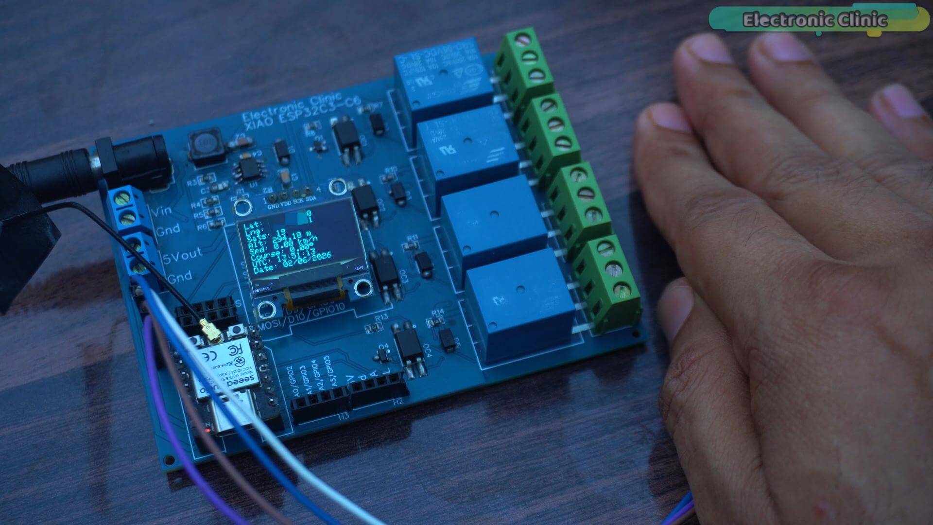
Hm. Nothing. Still 19. It is not moving at all. This thing is holding on.
Okay let me go further. I am grabbing a steel pot and covering it completely.
Watch, watch, there it goes. 18, Now 17, But wait, it just jumped back to 19. Interesting. There is some fluctuation but it is nowhere near the drop I was expecting.
Now let me try something different. I am going to flip the antenna facing downward, away from the sky completely.
And now you can see it. 18… 17… bouncing between the two. It is not happy but it is still holding a signal.
Okay, flipping it back to normal.
And there it is. Back to 19.
So what just happened here? A hand could not kill it. A steel pot could not kill it. That -162 dBm sensitivity we talked about earlier, this is what that number actually means in the real world. This module does not give up easily.
Satellite Count vs Accuracy Test
Now, I want to show you something practical. Something you will actually face when you deploy a GPS tracker in the real world.
I was planning to walk toward a building for this test, but then I looked at my house and thought,
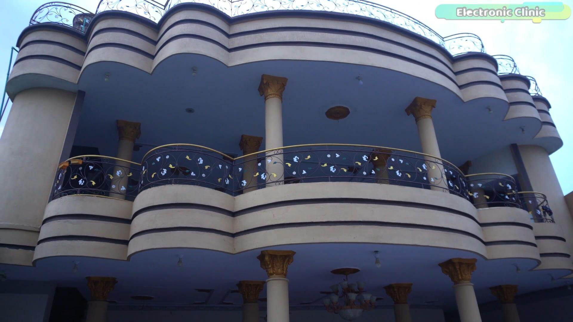
why go anywhere? This is already a two storey building. Ground floor, first floor, thick walls. This is the obstacle.
So I am taking it inside. Let’s see what happens.
And look at that; 11 satellites. Indoors. Inside a two storey house.
I mean that is genuinely impressive. This module is still talking to 11 satellites through the ceiling and walls above it.
Now let me cover the antenna with my hand.
Watch the count. It is dropping. The signal is getting weaker…
Now removing my hand…
And it is climbing back up… Back to where it was.
This is what I wanted you to see. Walls, ceilings, obstacles, they all reduce satellite visibility. But the moment you remove the obstruction, this module fights its way back. In the real world, buildings and trees will do exactly this to your satellite count. Now you know what to expect and what to look for.
Bluetooth GPS Tracker
Now this is where things get really interesting.
We are not changing a single wire. Same hardware. Same connections. Everything stays exactly the same.
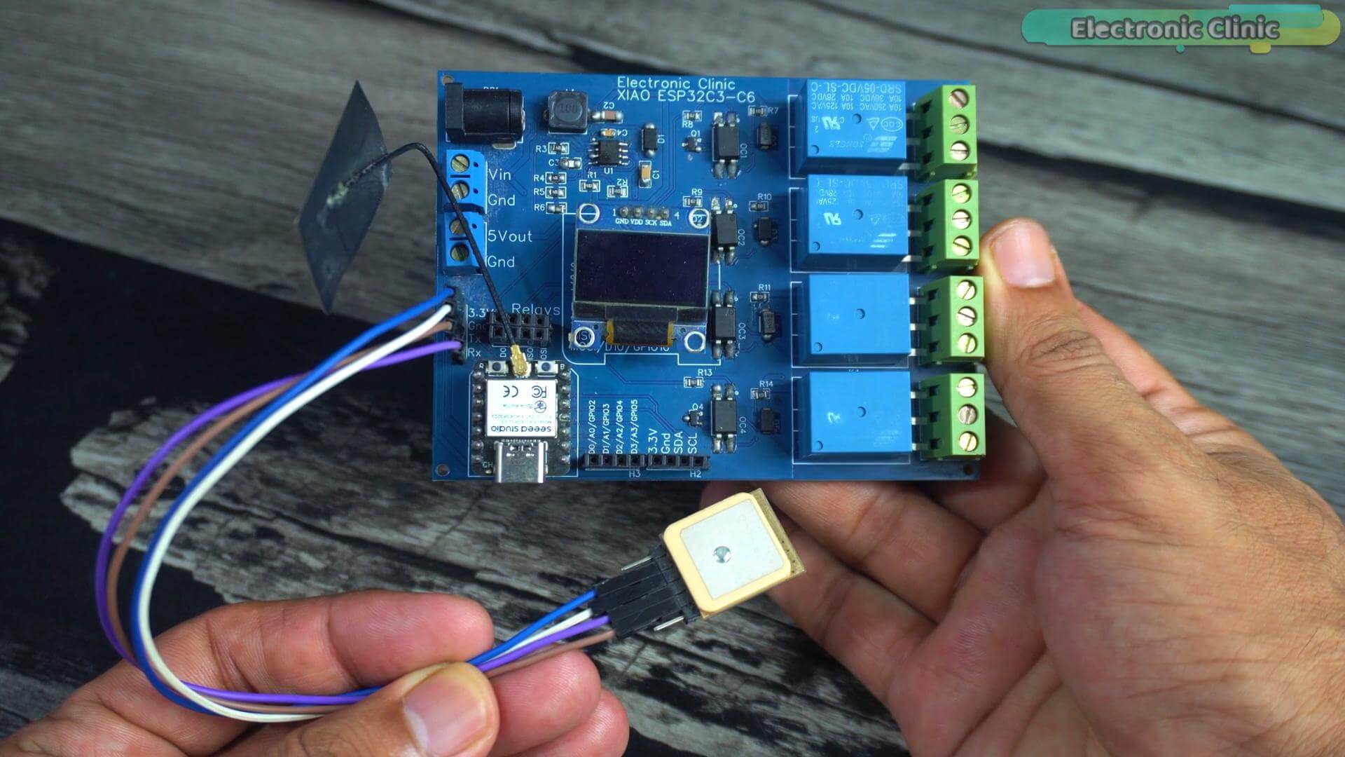
The only thing changing is the software.
Now I have already explained most of the important concepts in the previous example, GPS reading, decoding, OLED display. So I am not going to repeat all of that again.
What is new here is the Bluetooth part. Let me show you the key additions.
BLEDevice::init(“GPS_TRACKER”);
This one line gives the ESP32 its own wireless identity. When your phone scans for Bluetooth devices, this is the name it will find. Without this, your phone has no idea the tracker even exists.
String gpsData = String(actualLat, 6) + “,” +
String(actualLng, 6) + “,” +
String(actualSpeed, 1) + “,” +
String(actualAlt, 1);
pCharacteristic->setValue(gpsData.c_str());
pCharacteristic->notify();
This is where the magic happens. Every second, the ESP32 packages the latitude, longitude, speed, and altitude into one compact string, something like this:
24.860734,67.001136,8.2,34.7
And fires it directly to the phone using BLE notifications. Lightweight, fast, and no internet required.
if (deviceConnected)
{
display.fillRect(120, 0, 8, 8, WHITE);
}
And this tiny detail; a small square in the corner of the OLED; acts as a Bluetooth connection indicator. Simple but incredibly useful. One glance and you know whether the phone is connected or not.
That is all the new code. Clean and straightforward.
I have already uploaded this program to the board.
I already have the board powered on because in a little while we are going to pair it with the phone and track everything live on the map.
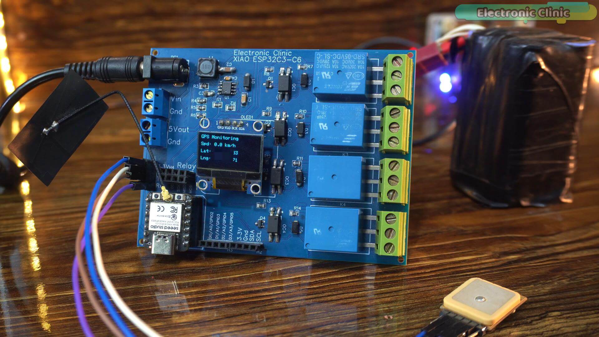
But before that I want to share something with you.
Look, we are indoors right now. And you already know that indoors, GPS accuracy is not perfect. So if you see the marker drifting a little on the map, do not worry about it. The GPS is stationary, and we are inside, so some small movement in the coordinates is completely normal.
But here is what actually impressed me. Despite being indoors and stationary, the speed value is showing zero most of the time. That is really good.
Alright. Now before we jump into the outdoor tests, let me show you the Android app I built for this project.
The Android Application for GPS Tracking
I designed this application entirely in Android Studio.
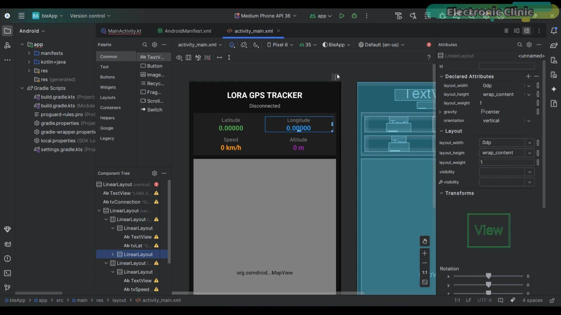
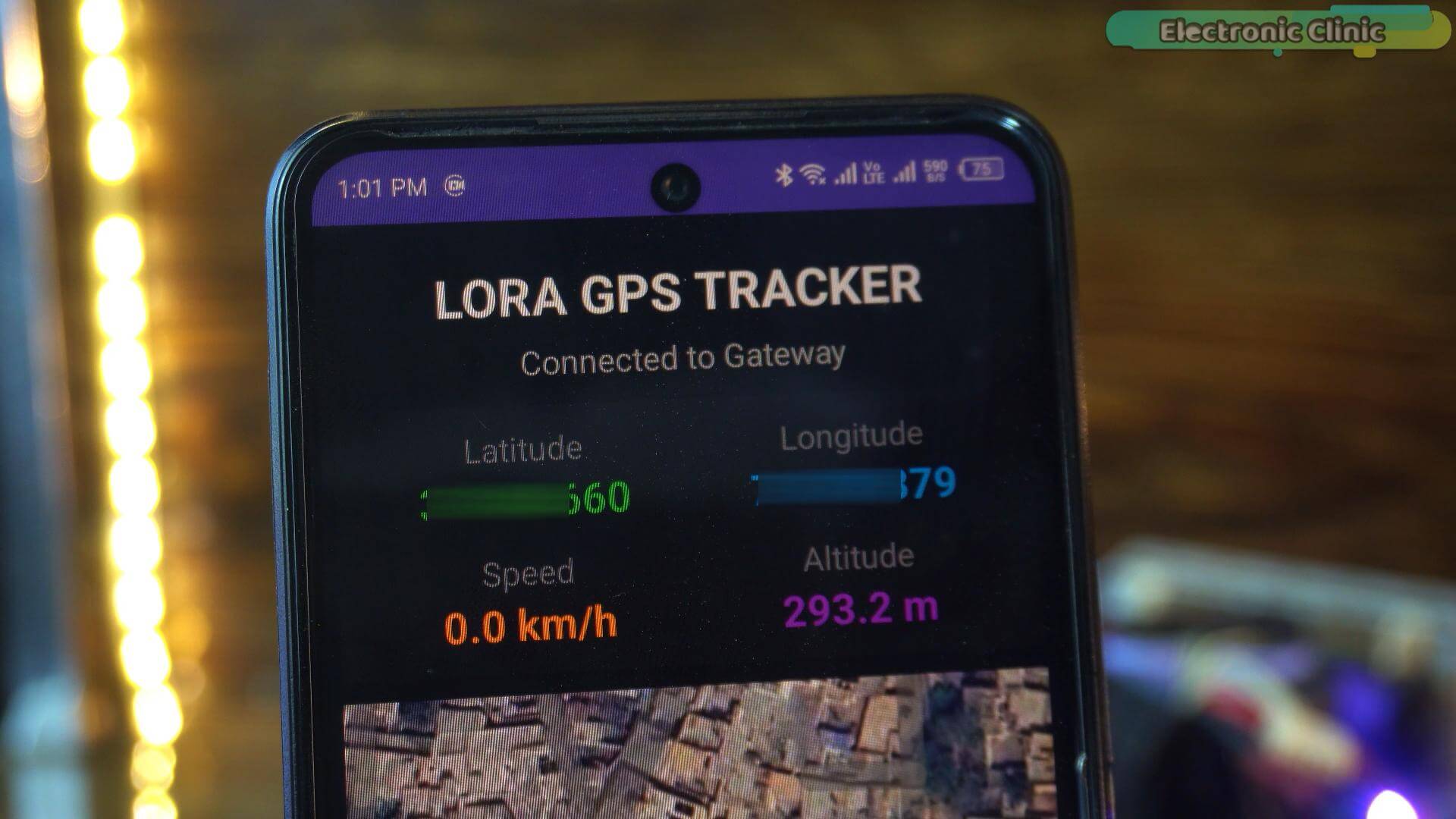
This is the layout file, activity_main.xml. This is where the visual interface is designed. You can see the connection status at the top, the four GPS value fields, latitude, longitude, speed, altitude, the map section below, and the connect button at the bottom.
This is the AndroidManifest file. This is where we declare the Bluetooth permissions the app needs to communicate with the ESP32. Without these permissions declared here, Android will simply block the Bluetooth connection.
And this is the main code file, MainActivity.kt. This handles everything, scanning for the GPS_TRACKER device, establishing the BLE connection, receiving the data packets, parsing them, updating the display, and plotting coordinates on the map.
Now honestly, this is a long file and walking through every line would take another full article. I have already created beginner friendly article about Android Studio and smartphone app development if you want to learn how this is built from scratch.
But if you just want to use this app right now, download the complete project from my Patreon page. The link is in the description.
Just open it in Android Studio, while your phone is connected to the system click the Play button and wait for a few seconds…
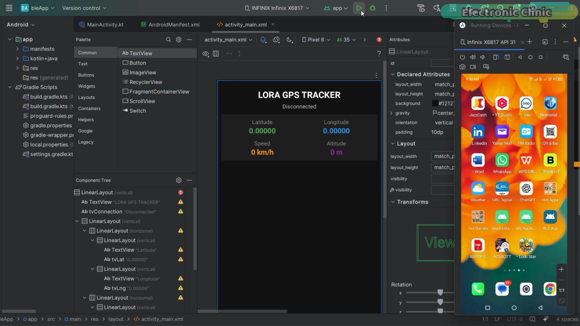
Turn on Bluetooth and let me tell you I have already paired my phone with the Bluetooth…
Connecting To The GPS Tracker
Right now it shows Disconnected and all values are at zero.
I press Connect to Gateway.
The app starts scanning.
And is connected immediately you can see the status is changed to “Connected to Gateway”.
Watch the values now.
Latitude. Longitude. Speed. Altitude. All updating live directly from the GPS module through Bluetooth.
No WiFi. No internet. No cloud server. Just direct wireless communication between the board and my phone.
Now let’s run some tests.
Live Dashboard And Map Tracking
Now watch the phone screen as I start moving.
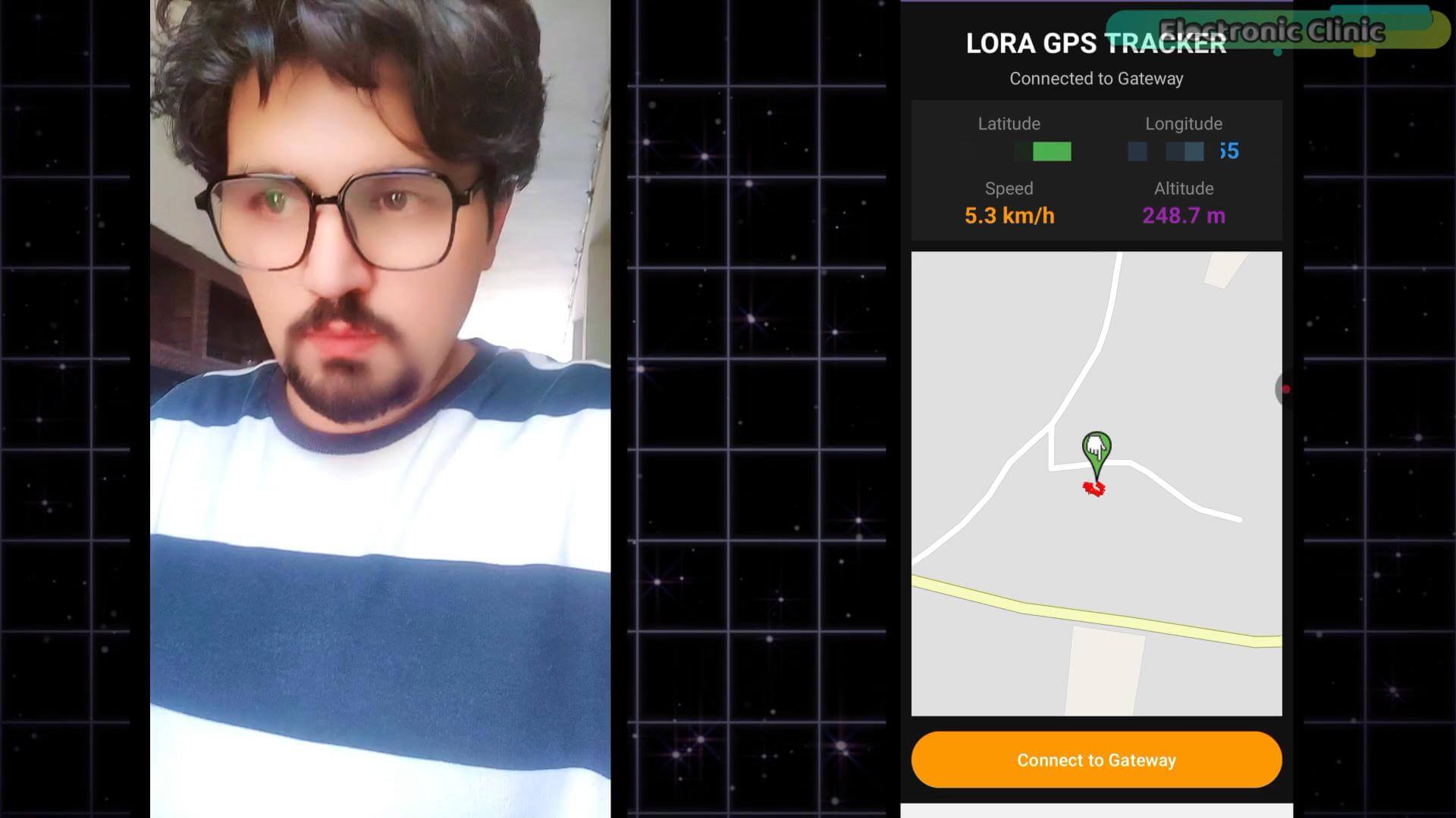
Latitude and longitude changing with every step. Speed jumping from zero the moment I move.
And altitude, I am saving that one for later. We are taking this tracker somewhere much more interesting to properly test altitude. Trust me, you do not want to miss that.
But look at the full picture here. Dashboard values updating live at the top, and below it, that marker moving in real time on the map. Every GPS update adding another point to the trail behind me. You can see exactly where I started, which direction I moved, and where I am right now.
Bluetooth Connection Indicator Test
Remember that tiny square we added in the corner of the OLED display?
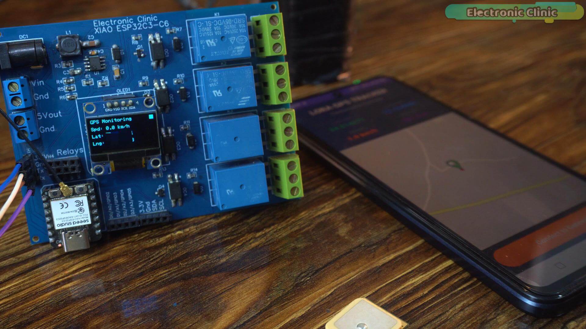
Three lines of code.
Eight pixels on a screen.
Watch it as I disconnect the app.
Gone.
Now reconnect.
I know it sounds like nothing. But when this tracker is mounted somewhere you cannot easily reach, that tiny square tells you everything you need to know at a single glance. Connected or not. No guessing. No checking the phone. Just look at the OLED and you know instantly.
Now before we move to the next version, let me talk about this map for a moment.
This map is powered by OpenStreetMap through the OSMDroid library.
And don’t get me wrong, it works perfectly. It is free, it requires no API key, no billing account, no Google account, nothing. You download the project, run it, and it works immediately. For a lot of projects and a lot of viewers, this version is completely sufficient.
But look at the map tiles closely.
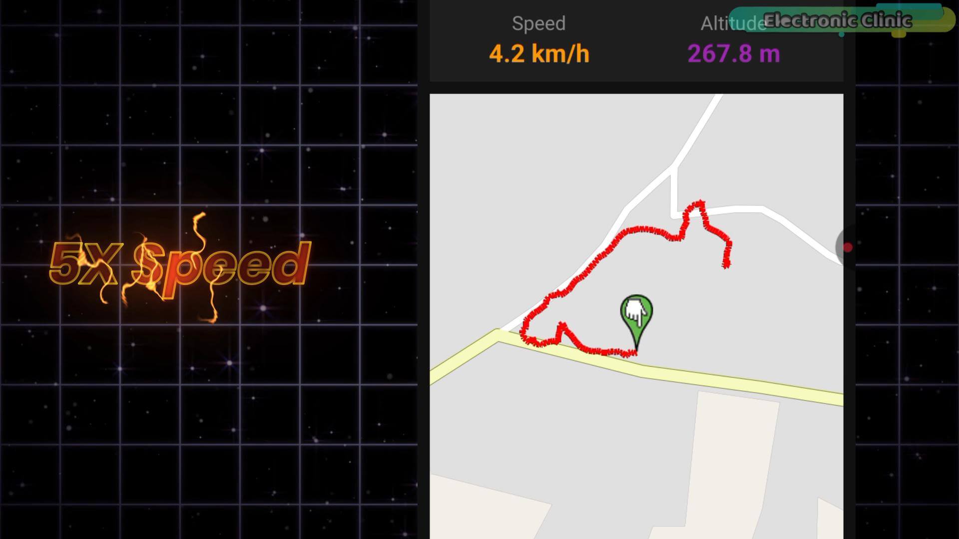
You cannot see actual buildings. You cannot see real terrain. You cannot see whether you are standing on a road, a footpath, or an open field. Everything looks the same, clean lines on a flat background.
And when you are tracking movement in the real world, that matters. A lot.
I wanted to see exactly where the tracker was. Not approximately. Not on a simplified drawing. I wanted to see the actual road, the actual building, the actual ground beneath the marker.
So I built a second version of the app.
Same Bluetooth connection. Same ESP32 code. Same GPS module. Nothing changes on the hardware side.
But this time the map is powered by Google Maps satellite imagery.
And the difference, you are about to see it for yourself.
Let’s go to version three.
GOOGLE MAPS SATELLITE TRACKING VERSION
Now at first glance this app looks almost identical to the previous one.
Connection status at the top. Latitude, longitude, speed, altitude. Connect button at the bottom.
Same layout. Same dashboard. Same everything.
But then you see the map, and it is immediately obvious this is something completely different.
You can see roads exactly as they are. Houses with their actual shapes and sizes. Trees, parking lots, open fields, footpaths, every single detail that exists in the real world is right there on your screen.
And when your marker moves across this map, when you can see yourself walking down an actual road or crossing an actual parking lot, the tracking experience feels less like a DIY project and more like something you would pay a monthly subscription for.
This is the version I personally use. And once you see it in action you will understand exactly why.
But before we can run this version there is one thing we need to set up first, a Google Maps API key.
Now I know the moment I say “API key” some of you immediately think complicated, expensive, confusing setup. So let me show you right now that it is none of those things. I am going to walk you through the entire process step by step and we will have it ready in just a few minutes.
Let’s do it together.
GENERATING THE GOOGLE MAPS API KEY
First, search for Google Cloud Console and open it.
Simply create an account if you don’t have one already. It is completely free to sign up.
Once you are logged in, click on APIs and Services.
Once everything loads up, scroll down and find Maps SDK for Android, and click on it to enable it. You can see I have already enabled it.
Now here I want to be honest with you.
I have already created a project here, you can see it, I named it My First Project. But after I finished building and testing this app, I disabled my billing account. So I cannot generate a new API key right now without creating an entirely new billing account, and I don’t want to do that just for a demonstration.
You can check your API Key by going to “Keys and Credentials”
Copy that key. Keep it safe. Because in just a moment I am going to show you exactly where to paste it in the project, and that is the only thing standing between you and a fully working Google Maps GPS tracker.
Now let’s add it to the application.
WHERE TO ADD THE API KEY
First things first, you can download this entire project from my Patreon page.
The link is in the description below. Just download it, open it in Android Studio, and then follow these exact steps to add your API key.
Once the project is open, find and click on the AndroidManifest.xml file. This is the file that tells Android everything it needs to know about your app, permissions, features, configuration.
Scroll down until you find this section:
<meta-data
android:name=”com.google.android.geo.API_KEY”
android:value=”YOUR_API_KEY_HERE” />
That’s the API Key.
Simply replace that with the API key you just copied from Google Cloud Console. That’s it.
Now let’s see the result.
SATELLITE TRACKING
Take a moment and just look at that map.
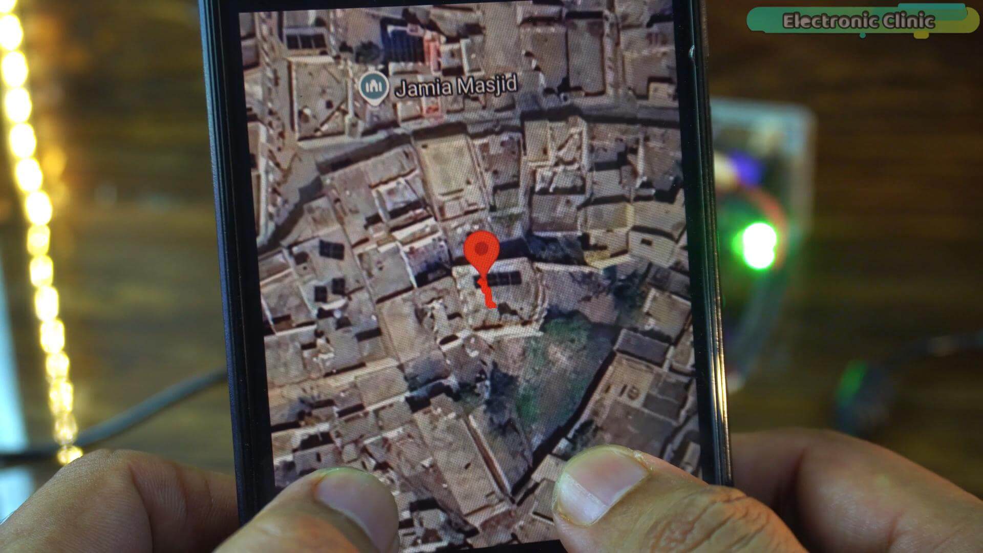
That is a real satellite image of my exact location right now, you can see my house, the neighbourhood around it, the surrounding houses, the open areas between them. Everything exactly as it exists in the real world.
Now I am going to step outside and I want you to watch the map very carefully.
Watch the marker moving across the satellite image as I step out.
You can see exactly which part of the house I just came out of. You can see me moving into the open area outside. The trail is drawing itself on a real image of my actual neighbourhood.
Now think about what is actually happening here. A module smaller than a coin is communicating with satellites 20,000 kilometers above the Earth, and placing itself accurately on a real satellite image of the area I am walking in right now.
This is the moment where the entire project stops feeling like a hobby build and starts feeling like something genuinely professional.
GPS. Bluetooth. Android. Satellite imagery. All working together on hardware that costs less than a dinner.
The Satellite Map Walking Test
I am going to walk a proper route right now, not just a few steps back and forth.
Watch the marker. Watch the trail. Watch how accurately it follows every turn I make.
The route is being recorded automatically with every GPS update. You can see exactly where I started, every turn I took, and where I am right now.
And because we are on satellite imagery, you can actually verify the accuracy yourself. You can see whether the marker is on the road, on the footpath, or drifting slightly. This level of visual feedback is simply not possible on a basic vector map.
This is what makes the Google Maps version so much more useful for real world applications.
Speed Test On The Move
Now let’s really push the speed monitoring.
You already saw the walking speed; so let’s skip that and go straight to something more interesting.
I am going to run.
Watch the speed value jump on the dashboard.

And look at the trail on the satellite map, notice how the points are spacing further apart compared to when I was walking. That spacing is actually a visual representation of speed. The faster I move, the further apart the trail points become.
But running is still not the most interesting speed test.
Let’s get in the car.
Watch the speed value now.
And here is something I want to try that I think you will find really interesting.
The car’s speedometer reading versus what the GPS module is reporting.
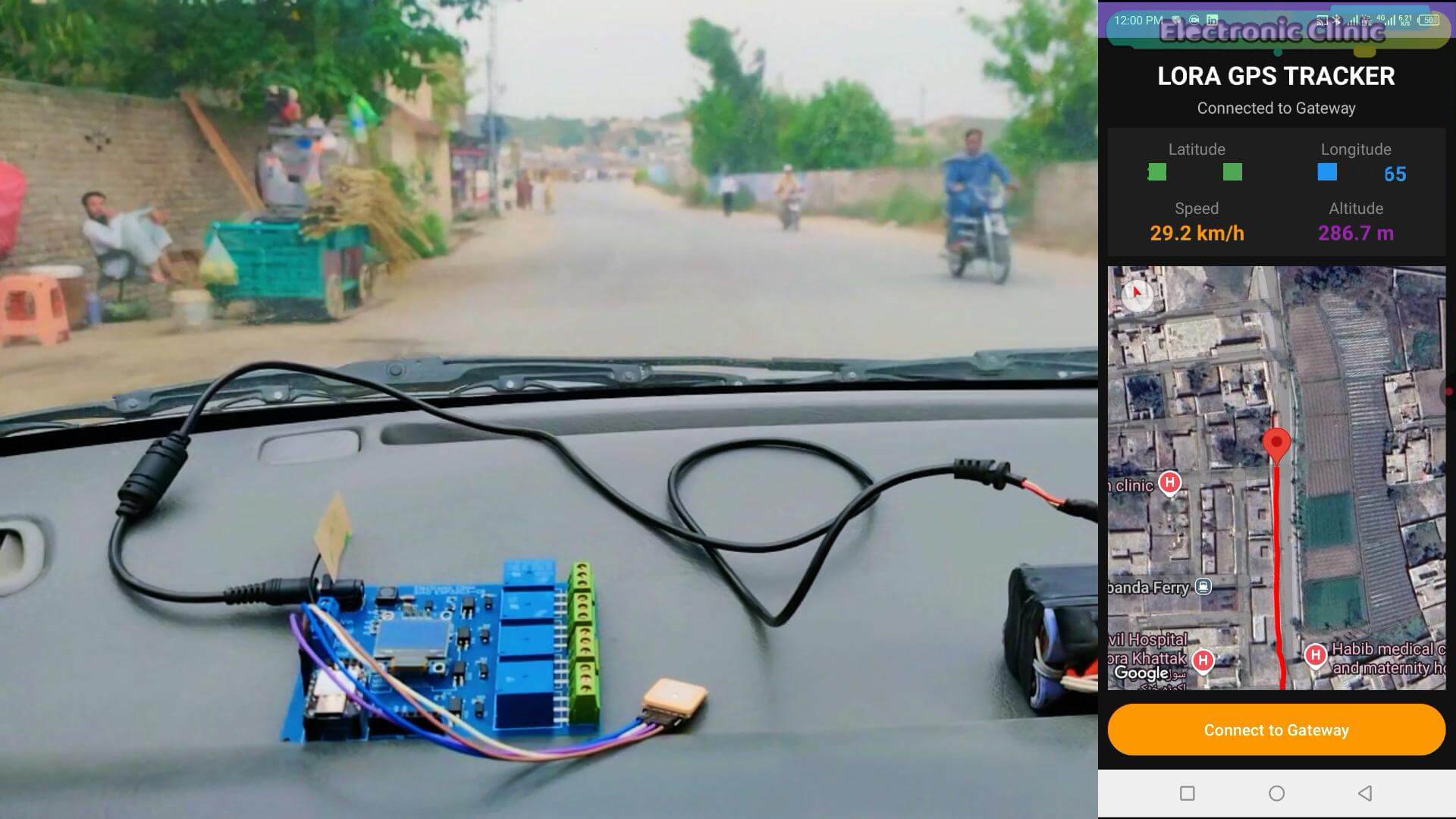
Look at that. The GPS speed and the actual car speed are incredibly close to each other.
Now this is significant. The GP-02 is not estimating speed. It is calculating it from your actual changing position between satellite updates.
I also tested it on the main road, and honestly, the accuracy completely surprised me. Out of all the tests I have performed so far, there wasn’t a single moment when the connection between the GPS module and the satellites was lost, not even for a second.
Now we are going to perform a much more demanding test. Over the next 4 kilometers, you will be able to compare the GPS track against both satellite imagery and the real-world footage captured by the camera.
During this test, the car won’t be moving at a constant speed. Sometimes we will be driving slowly, other times much faster. In other words, this is a true real-world test.
So keep an eye on the GPS track as we continue. By the end of this route, you will have seen enough to make your own judgment about the GP-02’s performance.
So far, as you can see, it is following the road remarkably well. I don’t see any noticeable drifting, and personally, I am very satisfied with the results.
But what do you think? Let me know your thoughts in the comments below.
Altitude Test
Remember earlier when I said we were saving the altitude test for something more interesting?
The wait is over.
I am on my rooftop right now. Look at the altitude reading on the dashboard, this is my current height above sea level, calculated entirely from satellite signals. No barometer. No additional sensor. Just the GP-02 talking to satellites in space.
Now look over there.
You can see that mountain from here. That is roughly one kilometer from my house. And I am going to take this tracker all the way to the top of it.
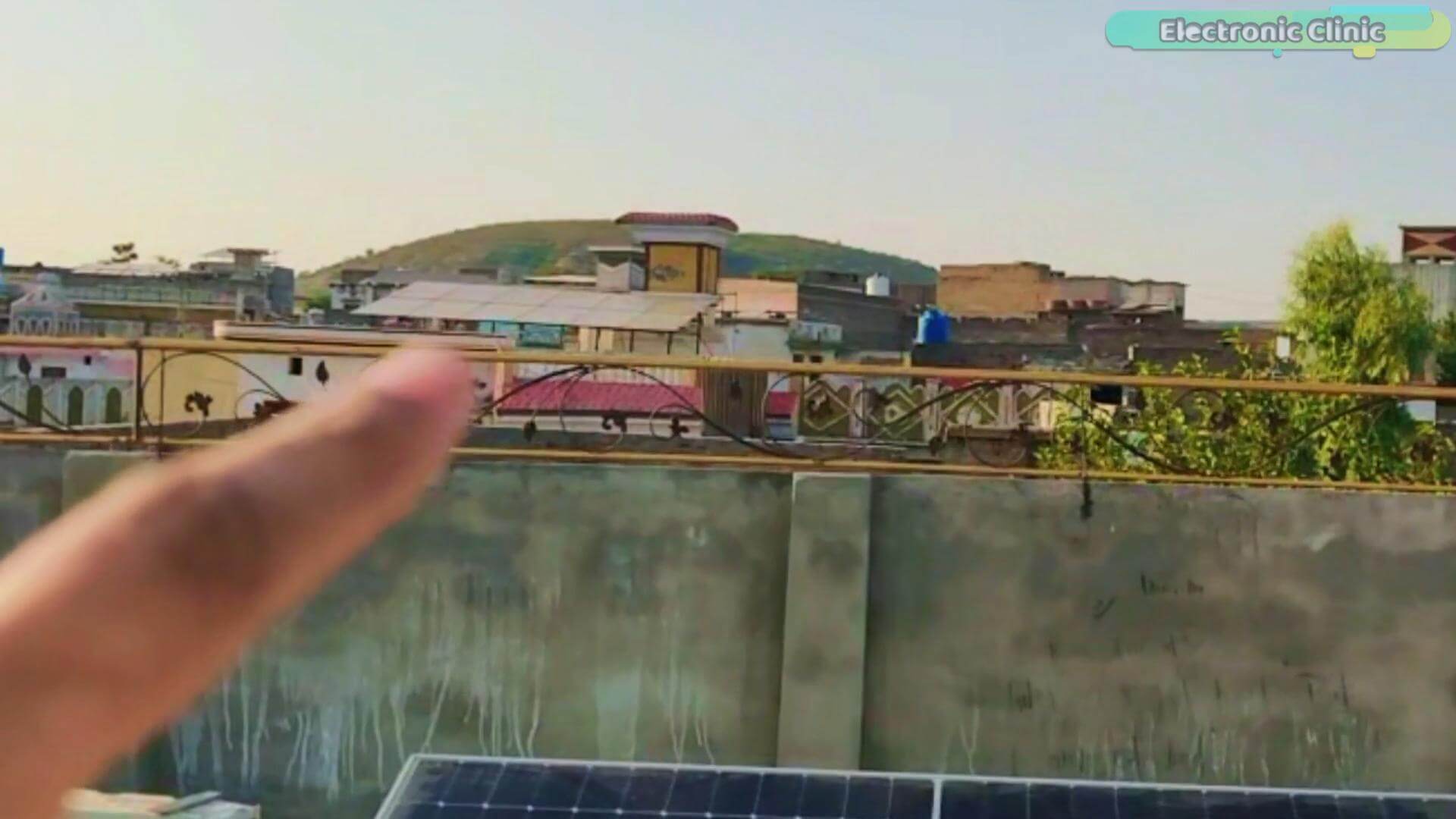
Let’s go.
This is not a short trip. The route takes us through different streets, narrow paths, and open areas before we even reach the mountain. So this should be a great real-world test for the tracker.
I will keep the screen recording running the entire time so you can watch the GPS data and altitude in real time as we make our way there.
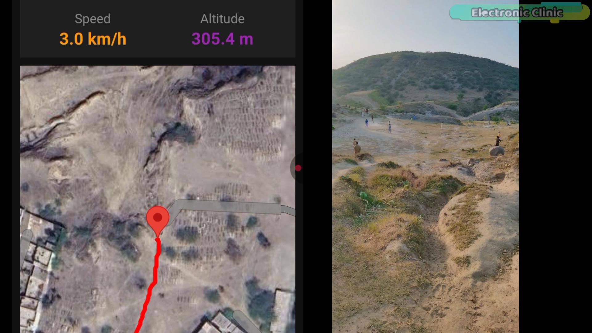
Since this is a fairly long journey, we will also find out how stable the GPS connection is, whether the tracker maintains a solid satellite lock, and if there are any signal dropouts along the way.
By the time we reach the mountain, we will have collected plenty of real-world data and a much better understanding of how well this tracker performs outside of a controlled test environment.
If you are still here, you are exactly the kind of person this channel is made for. So hit that Subscribe button, because the projects only get crazier from here. We have a lot more experiments, sensors, trackers, and AI-powered builds coming up.
Watch the number. Every step up the mountain and the altitude keeps climbing.
Look at that altitude reading now. Compare that to what we saw on the rooftop back home.
And if you look at the satellite map right now, you can see exactly where I am standing on the mountain. The trail shows the entire route I took to get here from my house.
This tiny GPS tracker just recorded a complete mountain hike. Altitude, route, speed, everything logged automatically.
My original plan was to make it all the way to the top of the mountain, but it’s already getting quite late. I think the main objective of this test has already been achieved.
Throughout the entire journey, the GPS signal didn’t drop even once,not even for a second. And as for the accuracy, you have already seen the results for yourself.
At this point, I think we have gathered more than enough real-world data to evaluate the tracker’s performance, and so far, it has been extremely impressive.
And look, I know what some of you are already thinking. Bluetooth range is limited. What’s the real world use case?
Fair question.
Because what we built today is actually called a gateway. Not just a tracker.
The next version of this project replaces Bluetooth with LoRa, and suddenly we are not talking about meters of range. We are talking kilometers. With geofencing. So the moment your bike, your car, or anything you care about leaves a zone you define, your phone gets an alert.
That project is coming. And everything we built today is the exact foundation it runs on.
So, that’s all for now.
Support me on Patreon:
If you enjoy my work and find these projects helpful, please consider supporting me on Patreon. With just $1, you can get access to all project source codes, schematics, and extra resources that I share with my supporters. Your support helps me continue creating new electronics tutorials, experiments, and open projects for the community. Thank you so much for being part of this journey and for supporting my work!
Watch articleTutorial:
Discover more from Electronic Clinic
Subscribe to get the latest posts sent to your email.