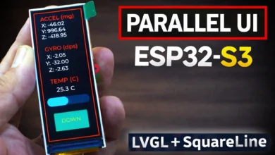
This $17 ESP32 S3 Runs LVGL Like a $200 Display + SquareLine Studio
Last Updated on September 22, 2026 by Engr. Shahzada Fahad
Table of Contents
Description:
Most people think building a touchscreen UI like this requires expensive hardware, months of experience, and hundreds of lines of graphics code.
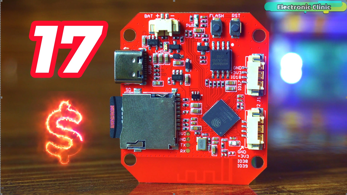
This is a 17 Dollars ESP32-S3 board.
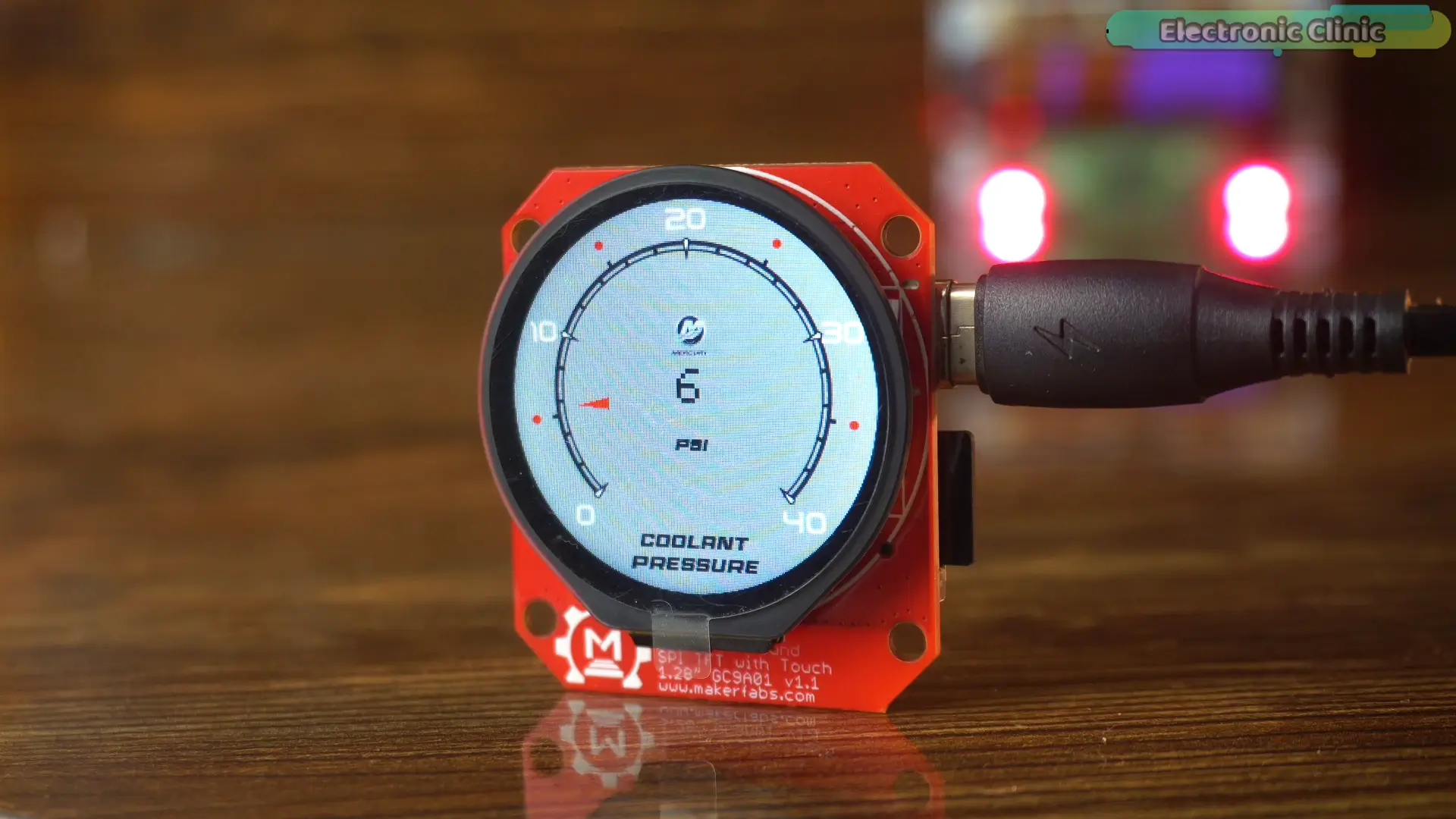
And every single screen you just saw was designed visually — without writing a single line of graphics code.
This is LVGL and SquareLine Studio.
And by the end of this article, you’ll build this exact project yourself.
INTRODUCTION
If you watched Part 1, you’ve already seen what this board is capable of.
But raw hardware capability and a professional touchscreen application are two very different
things.
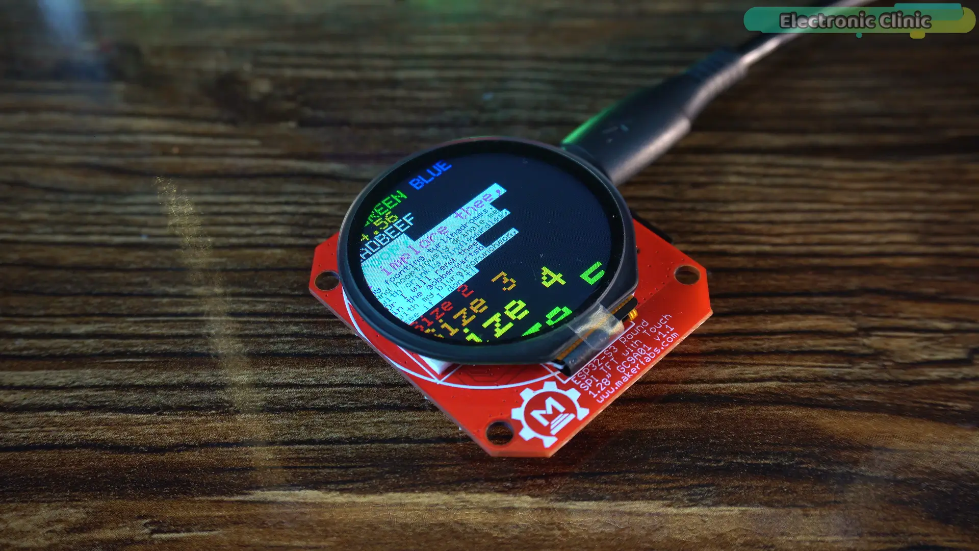
Today, we’re going to bridge that gap.
I’ll show you how to set up LVGL and SquareLine Studio correctly, build a reusable project template, create multi-screen interfaces, display live sensor data, and control real hardware directly from the touch screen.
But before we start, there’s something you need to know.
If you’ve ever tried getting LVGL running on a display like this and ended up with a black screen, wrong colors, or a project that uploads perfectly but does absolutely nothing…
The problem is usually not your code.
It’s the setup.
One wrong setting. That’s all it takes to waste an entire afternoon.
So in this article, I’m going to show you the exact setup I use from start to finish.
OPEN LOOP #1 — The Hidden Color Fix
And speaking of setup mistakes, there’s one thing almost every tutorial skips.
After every SquareLine Studio export, there is a single value hidden inside the generated UI files.
One value.
If you don’t change it, the colors on this display will be completely wrong.
The code will compile.
The project will upload.
But the interface won’t look the way it should.
I’ll show you exactly where it is and how to fix it.
OPEN LOOP #2 — The Sensor Problem
There’s another issue I ran into while building this project.
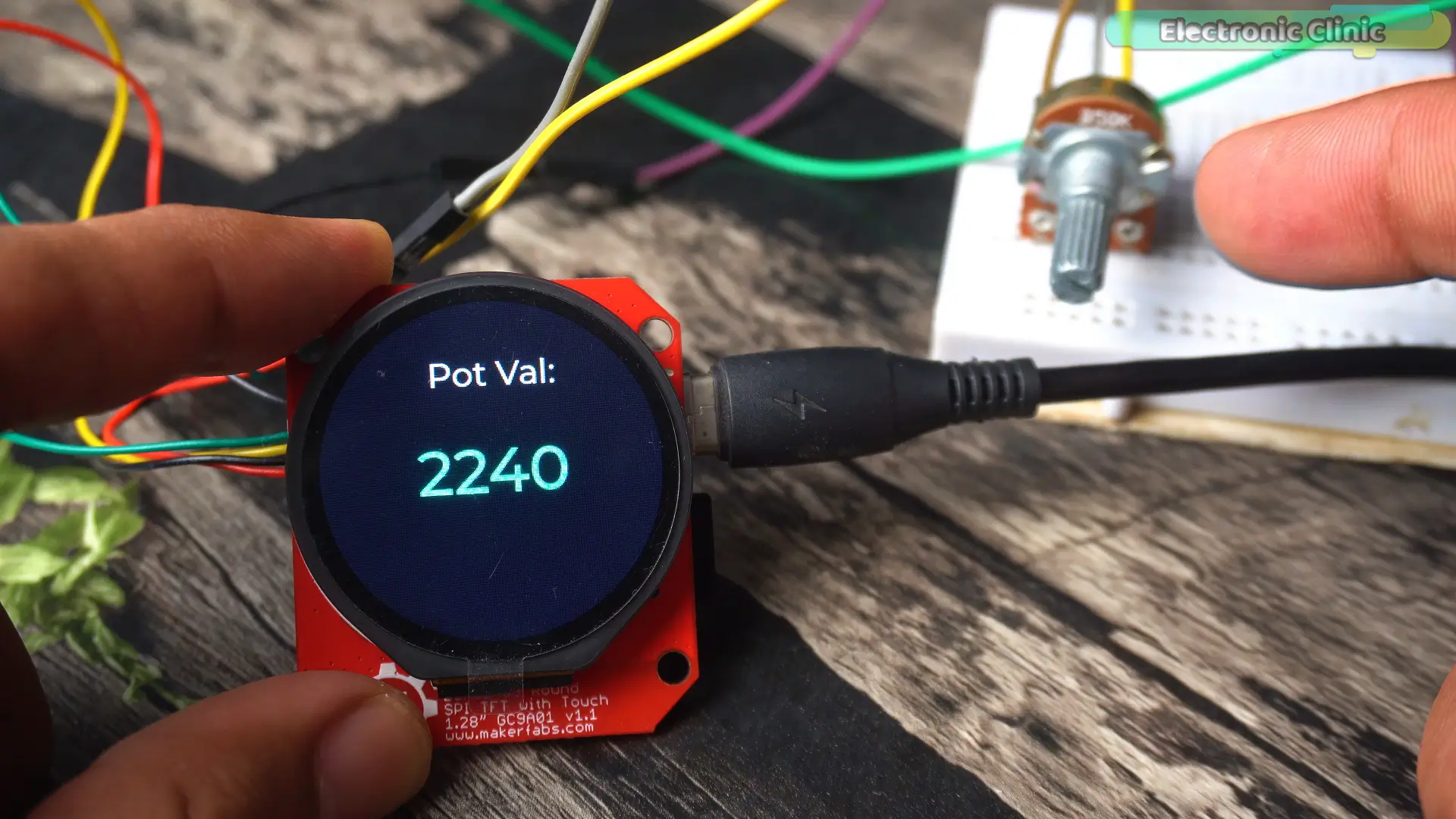
When I first ran the analog sensor example, the value on the screen was jumping constantly — even when I wasn’t touching the sensor at all.
At first, it looked like a hardware problem.
It wasn’t.
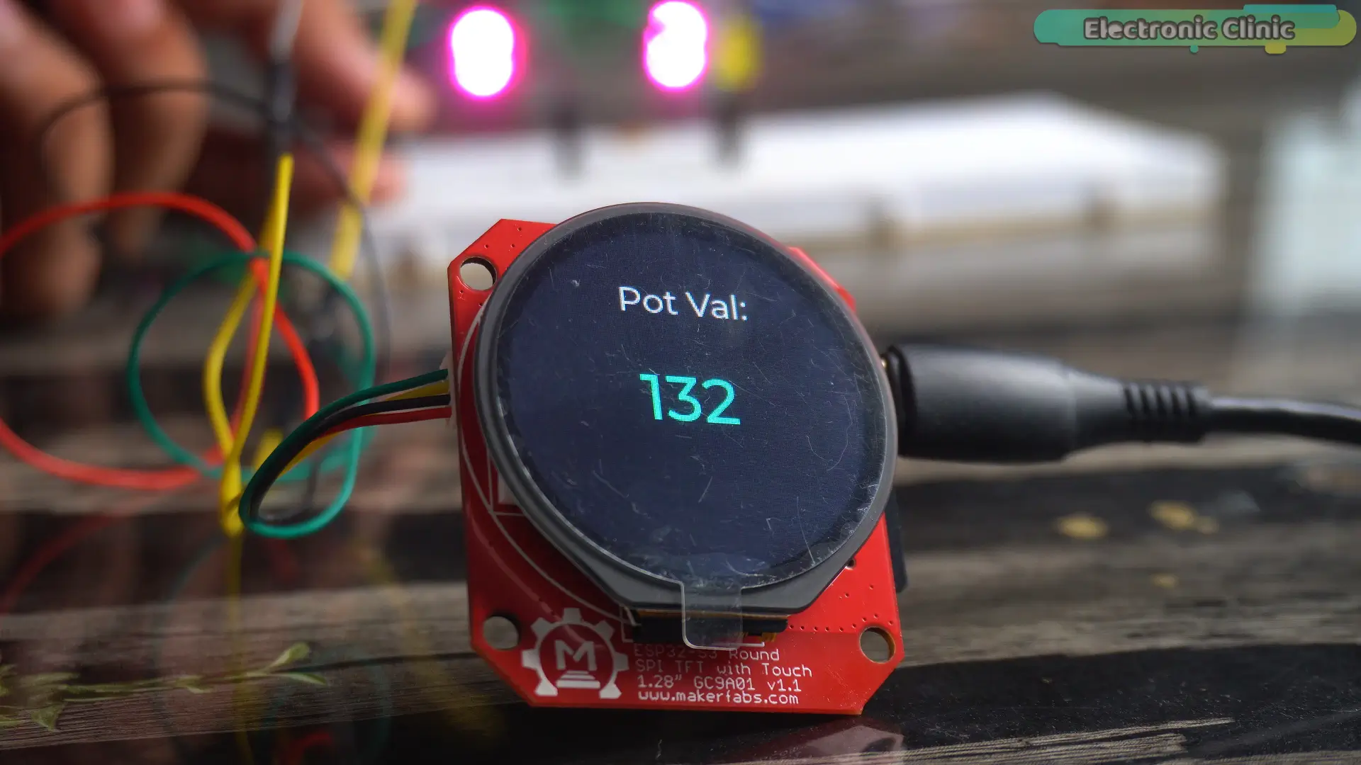
I’ll show you the simple three-step fix I used to make the readings stable and reliable.
OPEN LOOP #3 — The Reusable Template
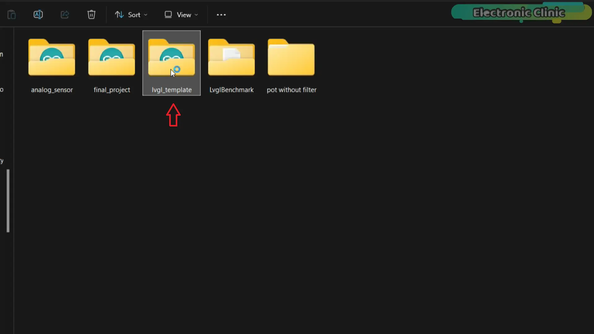
And finally, I’m going to share the exact project template I use for every LVGL project on this channel.
Once it’s set up, you won’t need to rebuild the entire project structure every time you start something new.
Set it up once.
Reuse it forever.
TRANSITION
So whether you’re completely new to LVGL, or you’ve tried it before and hit a wall…
This article covers everything.
The correct setup.
The hidden color fix.
The sensor stability fix.
The reusable template.
And a complete four-screen touch application built from start to finish.
So, without any further delay, let’s get started.
Amazon Links:
Other Tools and Components:
ESP32 WiFi + Bluetooth Module (Recommended)
Arduino Nano USB C type (Recommended)
*Please Note: These are affiliate links. I may make a commission if you buy the components through these links. I would appreciate your support in this way!
Software Setup and Libraries:
Alright, let’s build this from the ground up — correctly.
Before anything runs on this display,
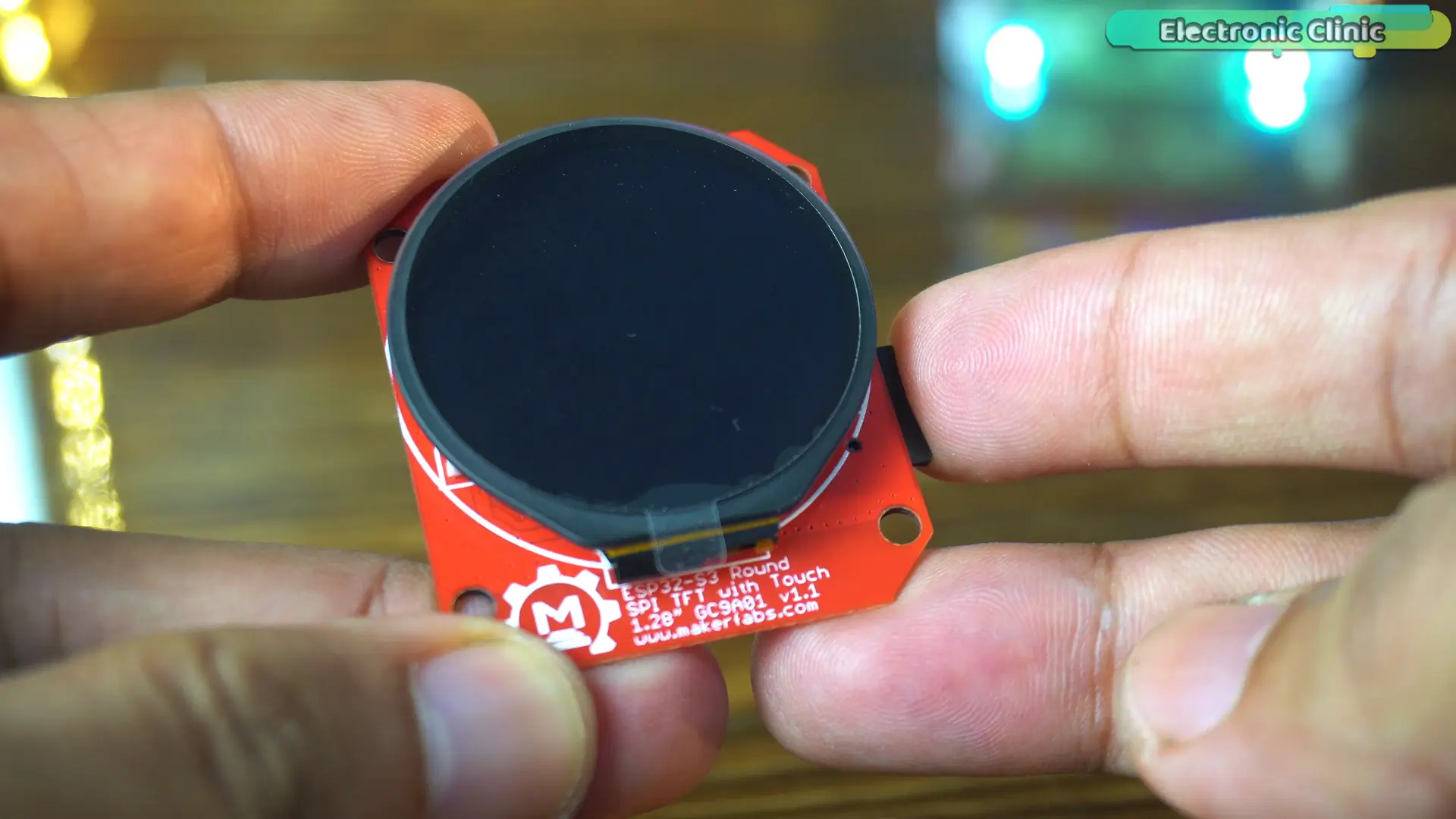
we need to set up the software environment. And this is where most people run into problems.
The first library you need is LVGL.
Open the Library Manager, search for LVGL, and install it.
Now pay close attention to the version number.
I’m using LVGL version 8.3.11.
This is the same version I’ve used across all of my LVGL and SquareLine Studio projects, and it’s the version I’ll be using throughout this tutorial.
Using a different version can lead to compatibility issues, compilation errors, or unexpected behavior. So for the best experience, I recommend using 8.3.11.
I’ve also linked my other LVGL and SquareLine Studio tutorials in the description if you’d like to explore these topics in more detail.
Once LVGL is installed, there’s one more important file we need: lv_conf.h.
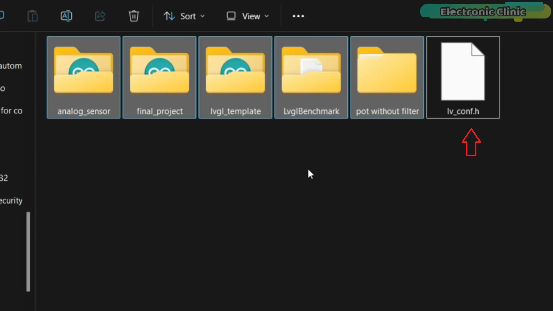
This file contains the configuration settings that LVGL uses throughout the project.
Without it, your project won’t compile correctly.
I’ve already prepared the file for you.
You can download the lv_conf.h file from my Patreon page, along with the complete source code, project files, and all resources used in this article.
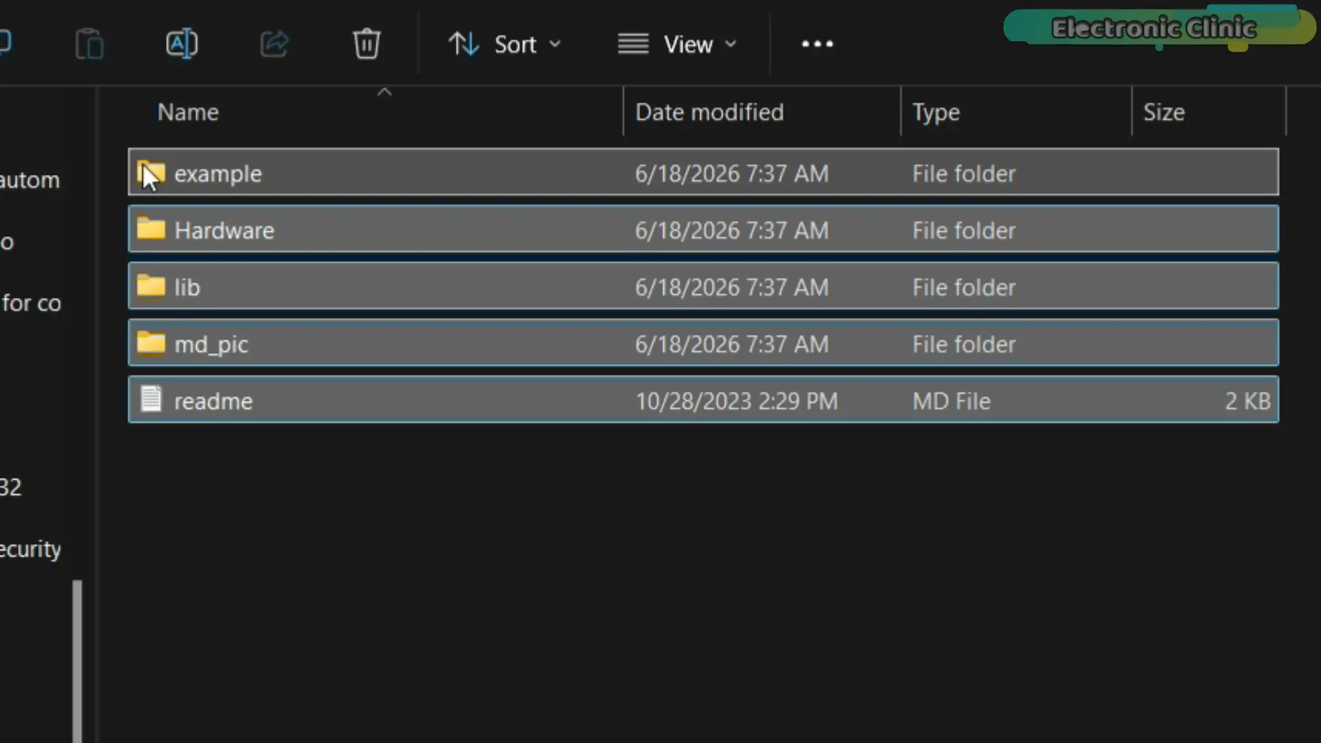
Once you’ve downloaded it, place it inside your Arduino libraries folder.
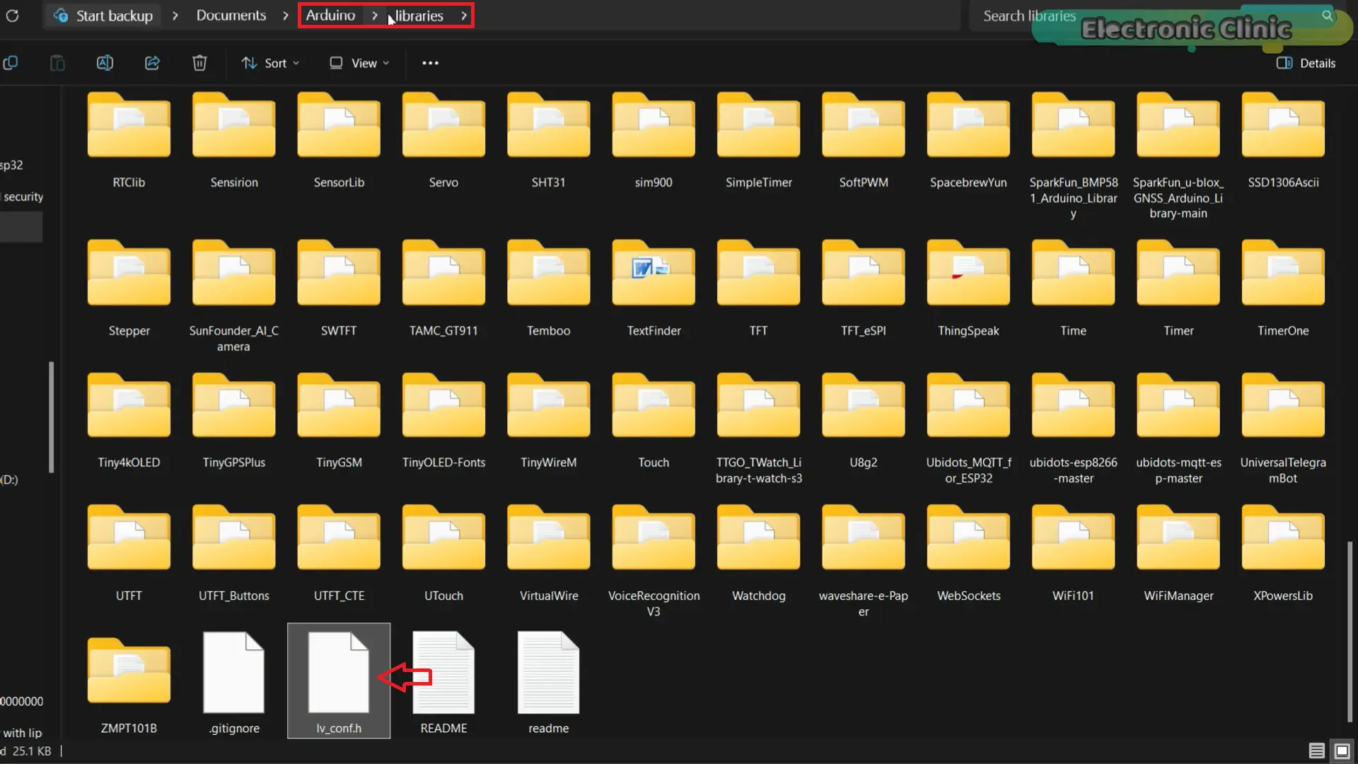
With that done, we’re ready for the next step.
LVGL Template Folder:
Now — this is the template I mentioned at the start of the article. The one that eliminates an hour of setup from every future LVGL project you build.
Let me open it and show you exactly what’s inside.
The structure is straightforward. Inside the main Arduino project folder, I’ve created two additional folders. The first folder stores the SquareLine Studio project files. The second folder stores the UI files that SquareLine Studio generates.
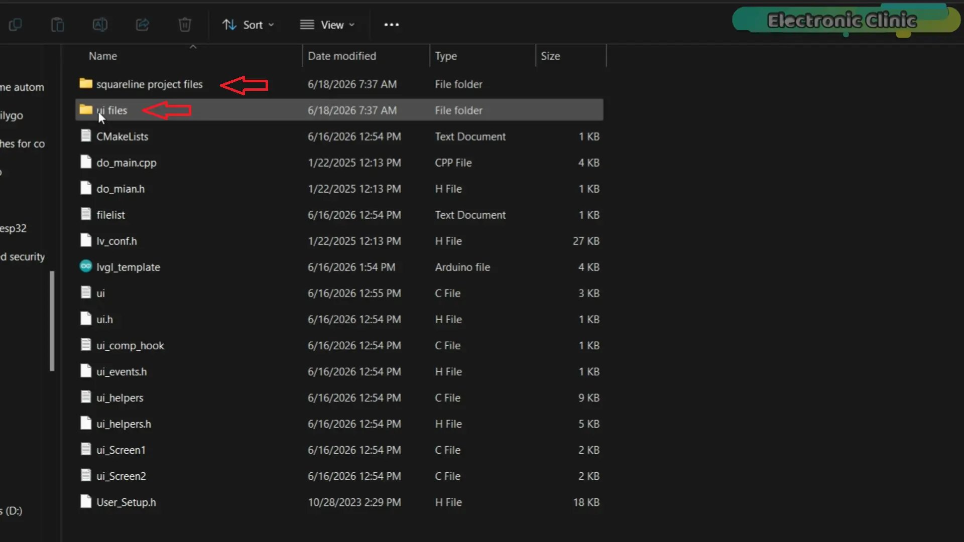
Then you copy those generated files and paste them along the Arduino .ino file. When you open the Arduino file all the files are automatically loaded.
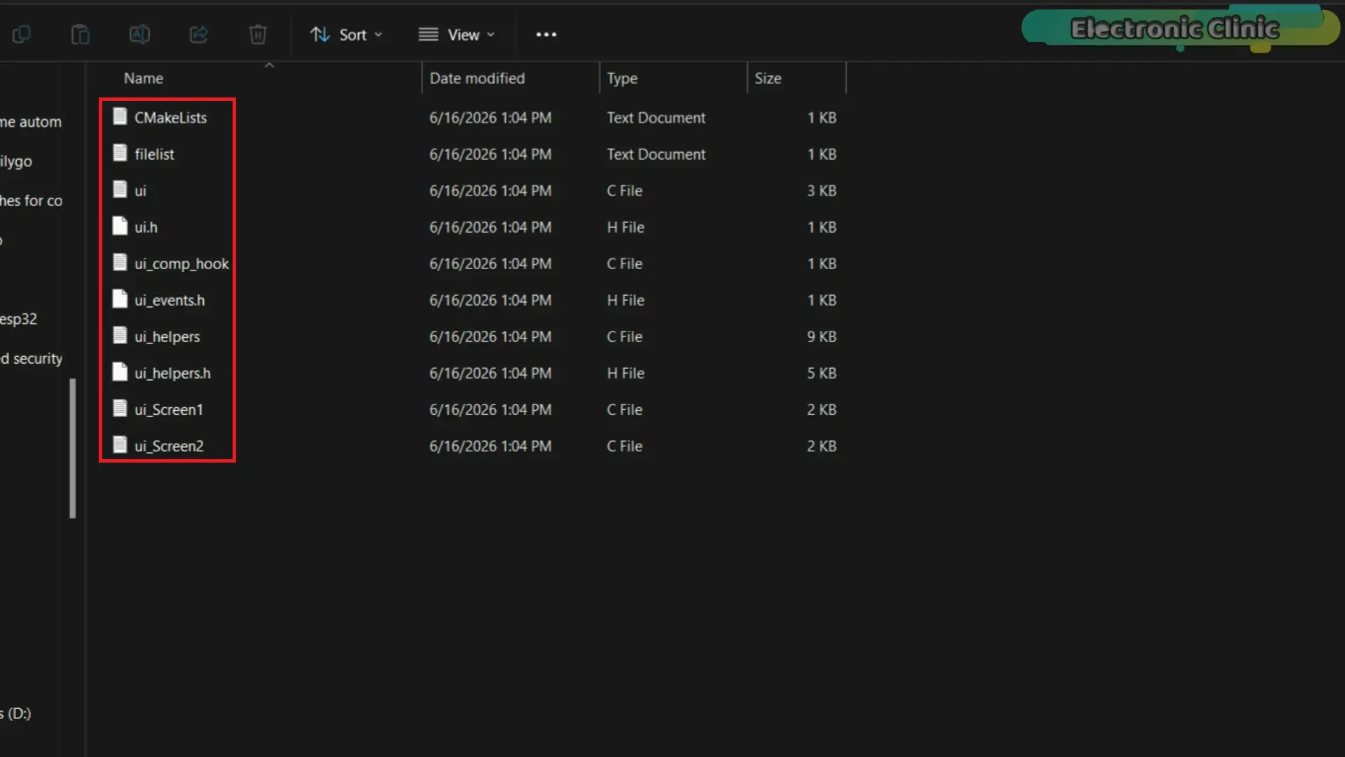
Now Makerfabs does include their own LVGL examples; but they use a different approach. The method I’m using is more flexible because it works with almost any LVGL project, not just this specific board.
In fact, every LVGL and SquareLine Studio project I’ve built on this channel uses this exact structure. Once you understand it, it becomes second nature.
Now here’s the part that matters most.
Almost 95% of the code in this template stays exactly the same across every project you’ll ever build with it. You configure it once. And you never start from scratch again.
The project is already configured and ready to upload.
But there is one critical step you must do after every single SquareLine Studio export.
This is the hidden configuration fix I mentioned in the intro. Here it is.
Open the ui.c file.
Find this line: LV_COLOR_16_SWAP
It will be set to 1. Change it to 0.
That’s the fix.
Here’s why this matters — and why it specifically affects displays like this one.
When LV_COLOR_16_SWAP is set to 1, the red and blue color channels get swapped in memory. The display driver on this round TFT processes color data in a specific byte order, and when that setting is wrong, the colors come out completely incorrect. Reds look off. Whites look strange. Your entire interface looks broken — even though your code and your design are perfectly fine.
Most LVGL tutorials are built around rectangular displays that don’t have this issue, so they never mention it.
On this round display, it matters every single time.
Change it to 0 after every export. Make it part of your workflow.
Once that change is made, the project is ready to compile and upload.
Uploading the Code:
Now let me show you how to upload your first program.
The good news is that you only need to configure these settings once. After that, you’ll use the same setup for all of the remaining examples in this article.
And if you’ve ever run into upload errors, display issues, or programs that compile but don’t run correctly, there’s a good chance one of these settings was the reason.
So let’s quickly go through them.
First, go to Tools > Board > ESP32 and select ESP32S3 Dev Module.
Next, go to Tools > Port and select the correct communication port.
Then enable USB CDC On Boot.
After that, go to Tools > Flash Size and select 16MB.
Next, go to Tools > Partition Scheme and select:
16M Flash (3MB APP / 9.9MB FATFS)
And finally, go to Tools > PSRAM and select:
OPI PSRAM
Once these settings are configured, simply click the Upload button.
The code has been uploaded successfully.
Now, let me show you what you have to do on the SquareLine Studio side.
Importing Project in SquareLine Studio:
Now, let’s go ahead and import this project into SquareLine Studio.
SquareLine Studio Setup
I am currently using SquareLine Studio version 1.5.0. To import the project,
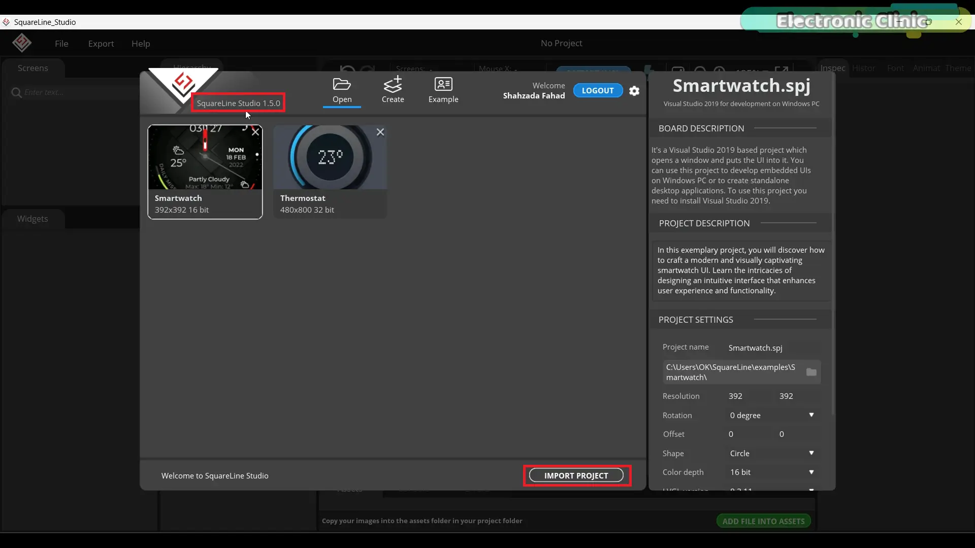
click on the Import Project button, browse to the project location, select the project file, and then click Open.
As you can see, the project has now been successfully imported. On the right-hand side, you’ll find the Project Settings, where you can configure all the important options.
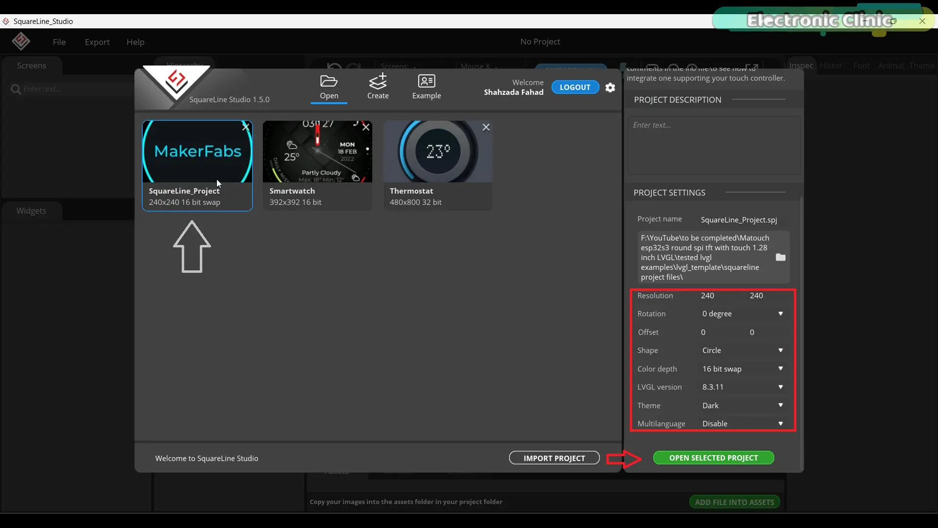
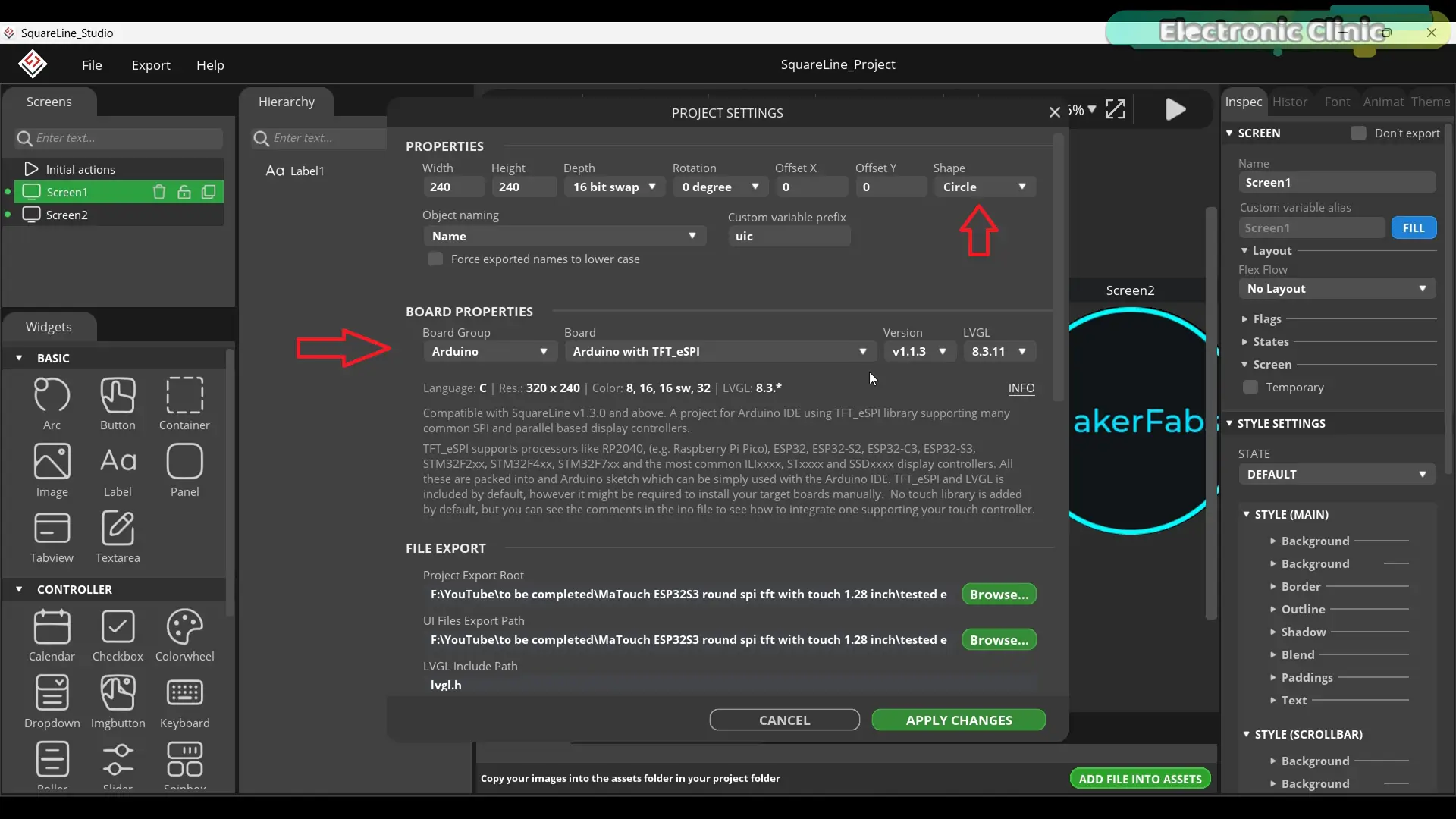
The display resolution is set to 240 by 240, which matches the display we’re using. The rotation is set to 0 degrees, and there’s no offset applied, so both X and Y offsets are set to zero. The shape is selected as Circle.
For color depth, I’m using 16-bit swap, which works perfectly with this display and LVGL. The LVGL version is set to 8.3.11, and the theme is Dark, which gives a clean and modern look while designing the UI. I’ve also kept multilanguage disabled for this project, since it’s not required right now.
These settings are very important, so make sure they match your display and LVGL version before moving forward.
Go to the File menu and then open Project Settings.
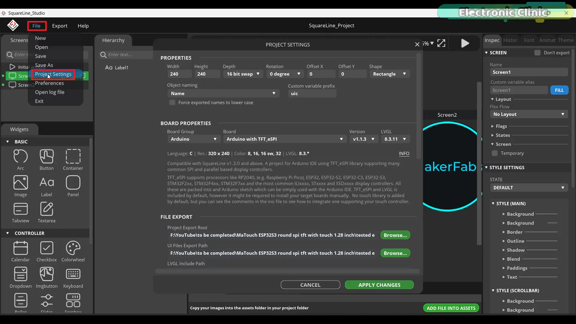
First, make sure the Project Properties are exactly the same as shown on the screen. Also, confirm that the Board Properties are set correctly and match these settings.
Next, under File Export, set the Project Export Root to the folder where you want to save your SquareLine project files.
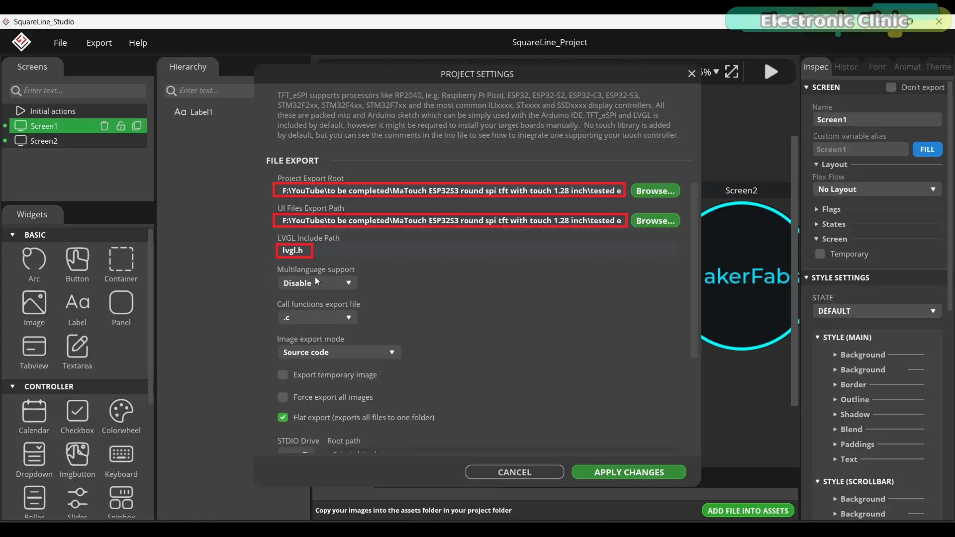
After that, set the UI Files Export Path as well.
For the LVGL Include Path, simply type lvgl.h.
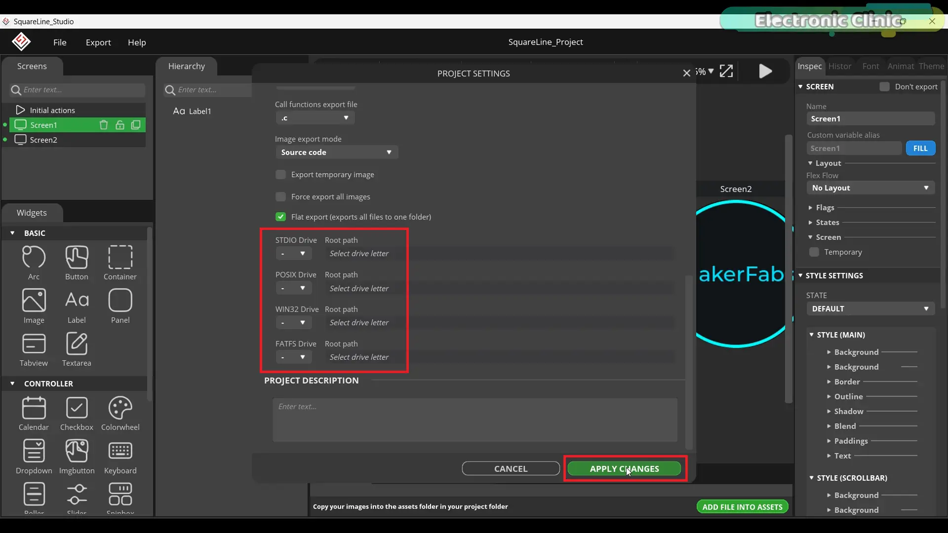
Now scroll down and make sure Flat Export (export all files into one folder) is checked. Finally, go ahead and click the Apply Changes button to save everything.
FIRST EXAMPLE — BASIC MULTI-SCREEN
For this first example, I’ve kept the interface intentionally simple.
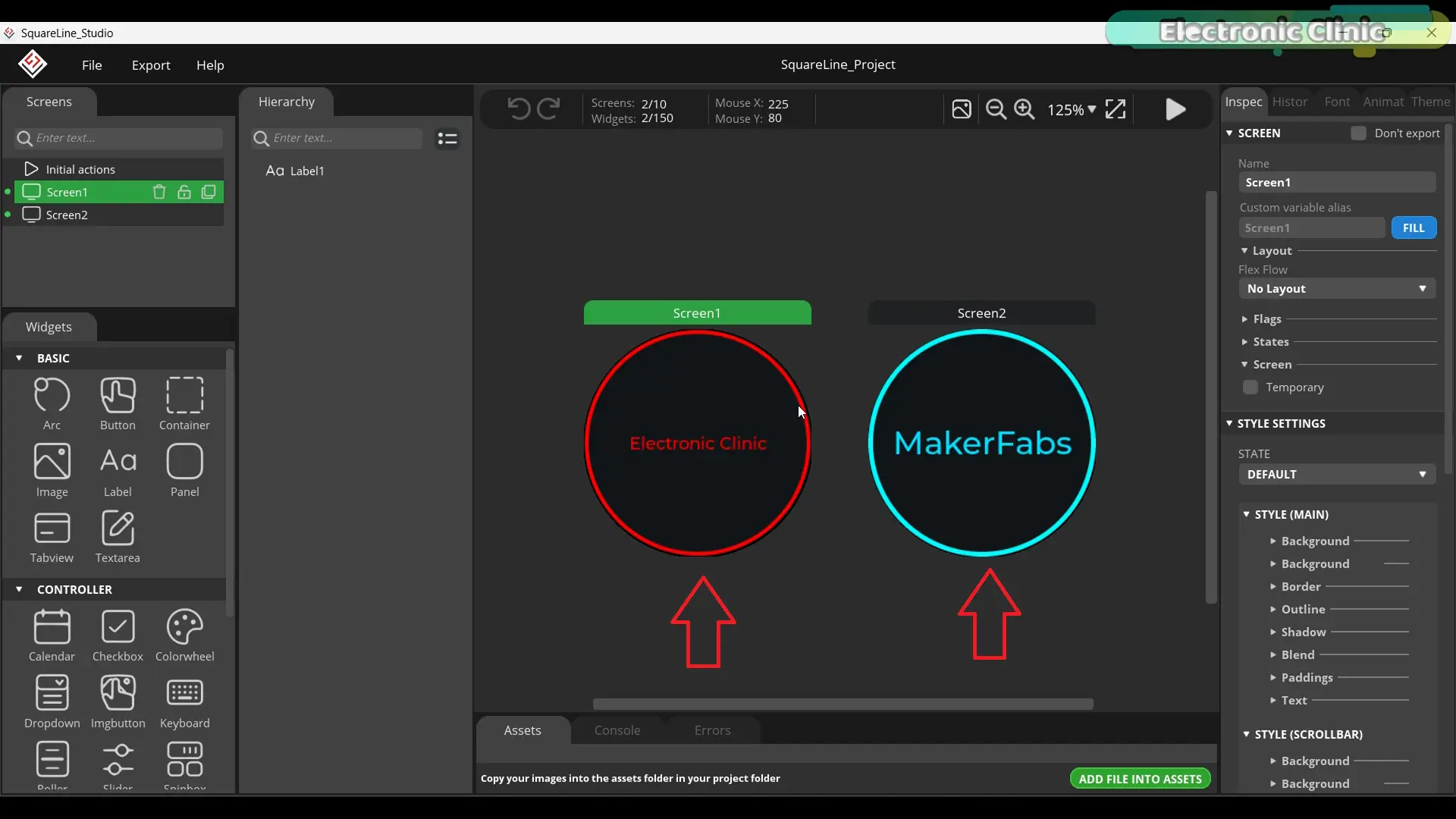
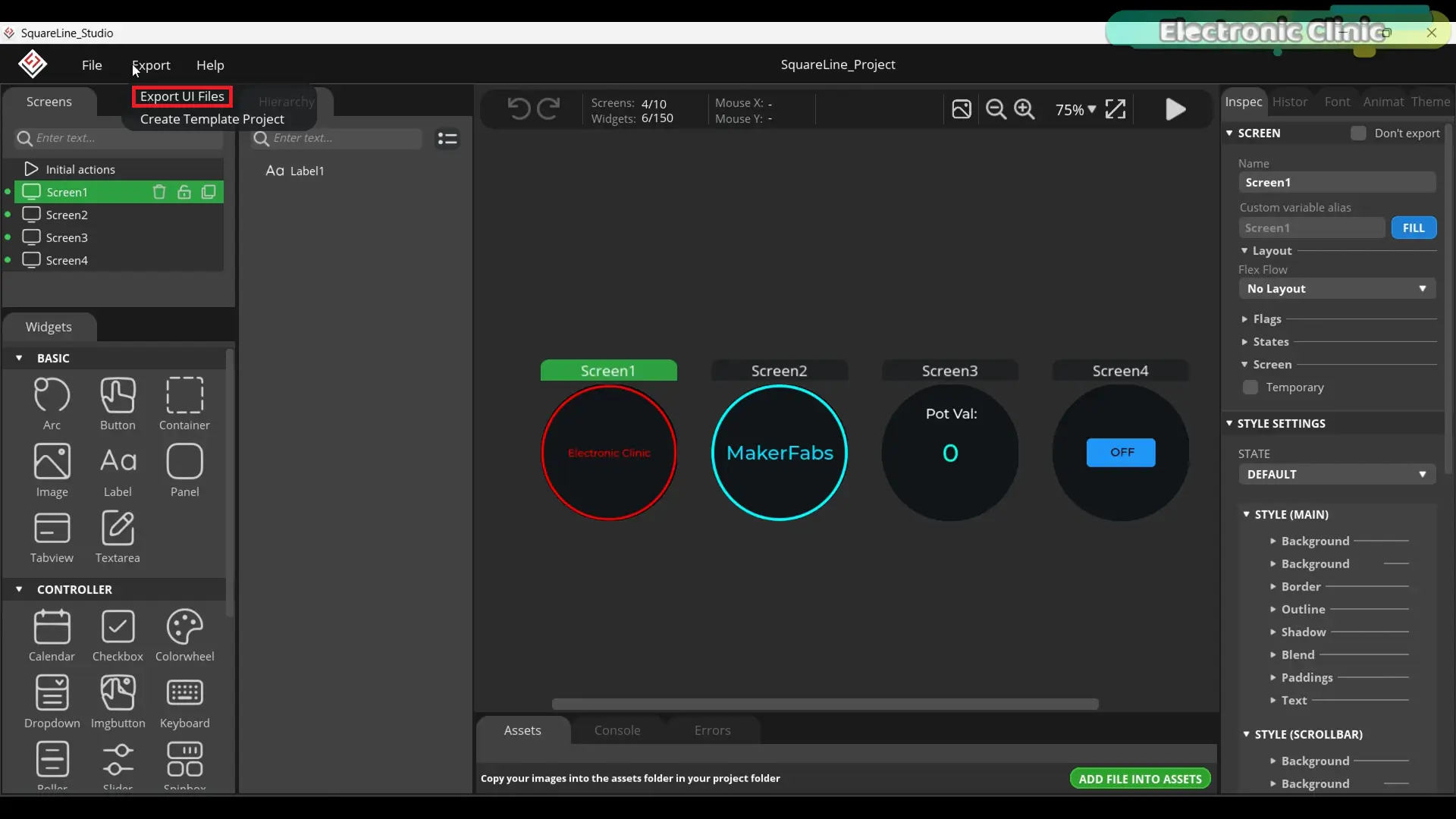
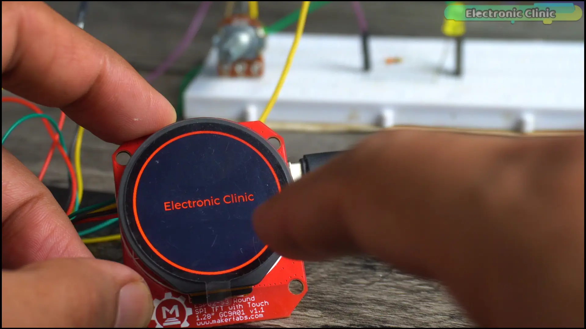
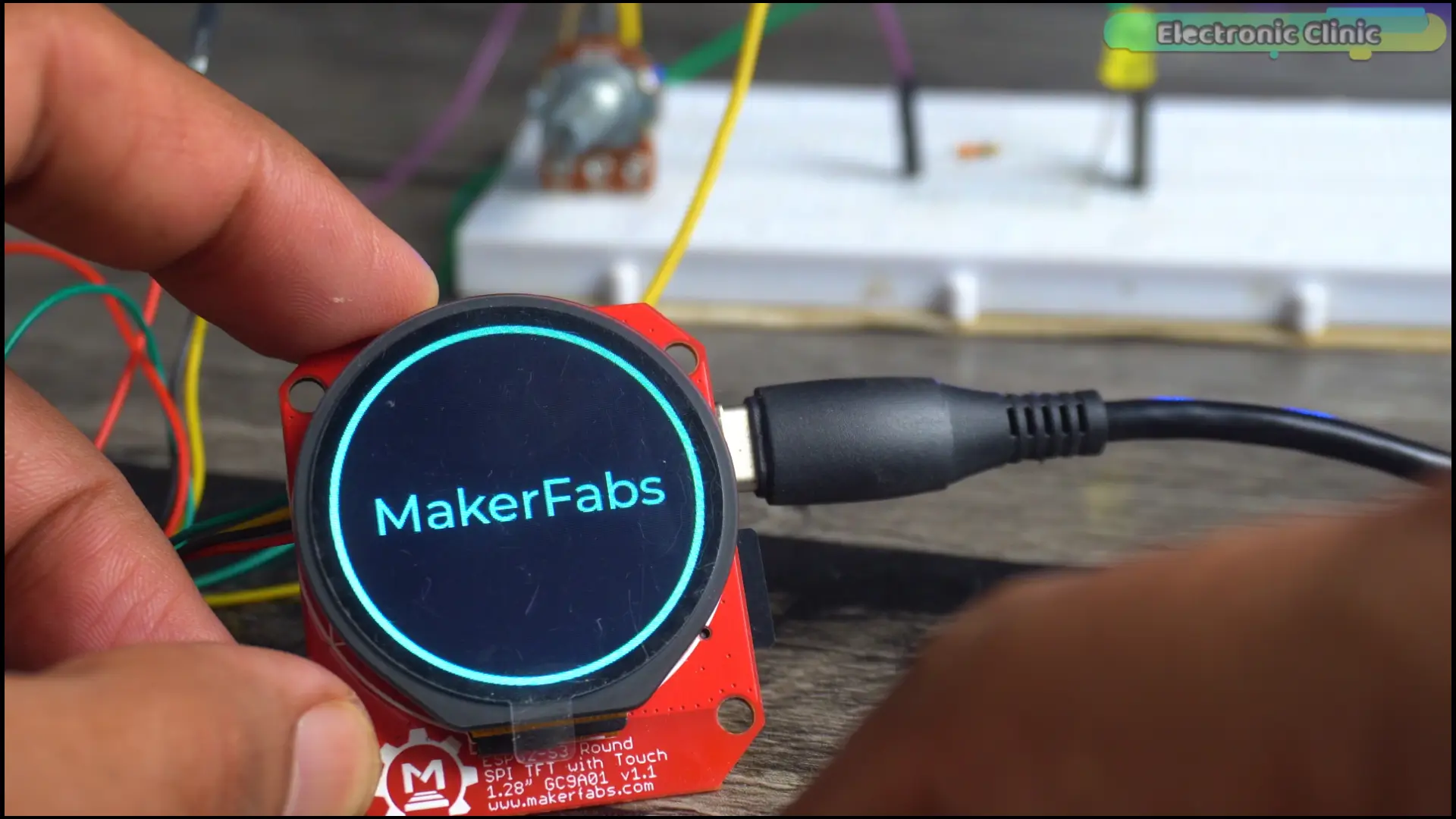
Two screens. Screen one shows “Electronic Clinic.” Screen two shows “MakerFabs.”
Here’s why I start this simple.
Before you build anything complex in LVGL, you need to confirm that every layer of the system is working correctly. The display driver. The touch controller. LVGL itself. The template. The board settings.
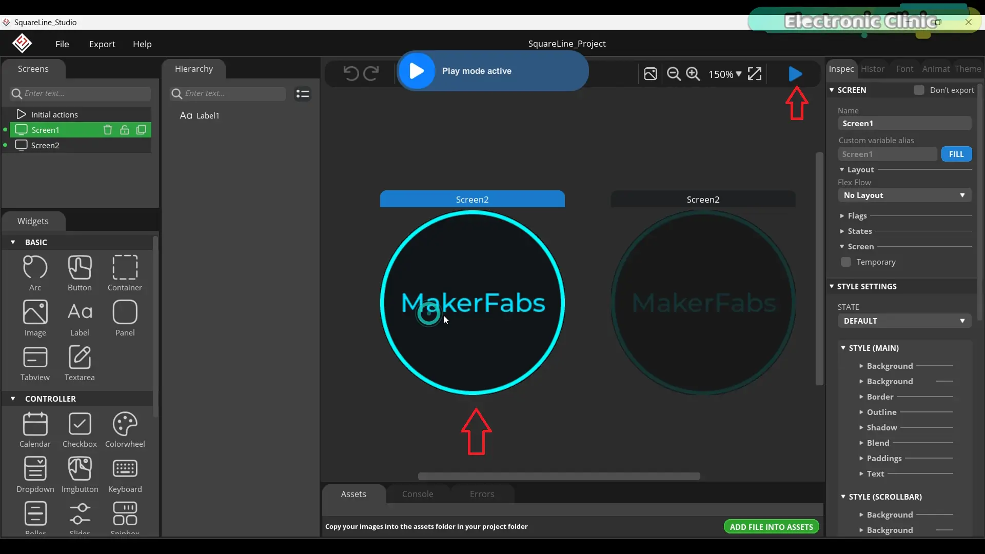
If you jump straight into a complex interface and something doesn’t work, you won’t know which layer broke it. Debugging that wastes hours.
Start simple. Confirm everything works. Then build on top of a proven foundation.
Let’s generate the UI files.
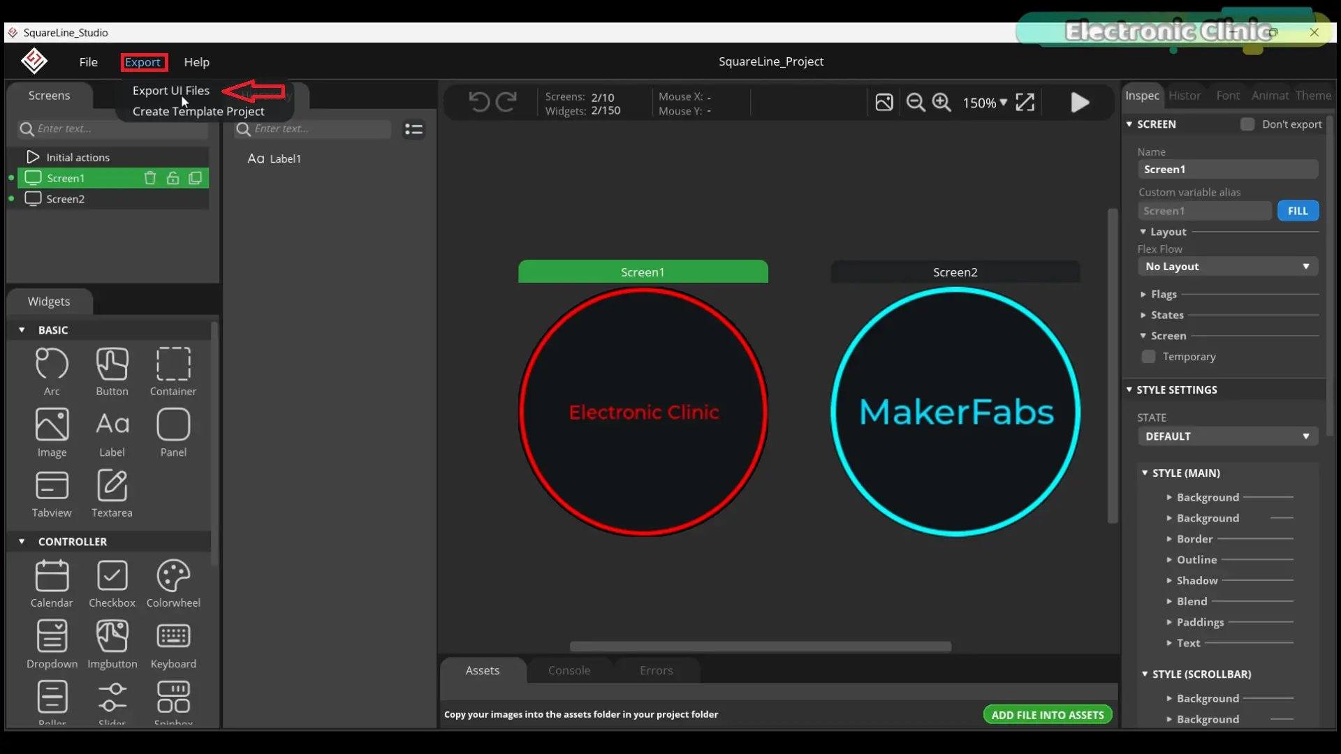
Go to the Export menu and click Export UI Files.
Take those generated files,
copy them, and paste them into the UI folder inside your Arduino project.
Open ui.c and change LV_COLOR_16_SWAP from 1 to 0.
Upload using the same board settings as before.
Practical Demo:
Both screens are active. Touch is responding. Swiping between screens works perfectly.
LVGL is running correctly on this board.
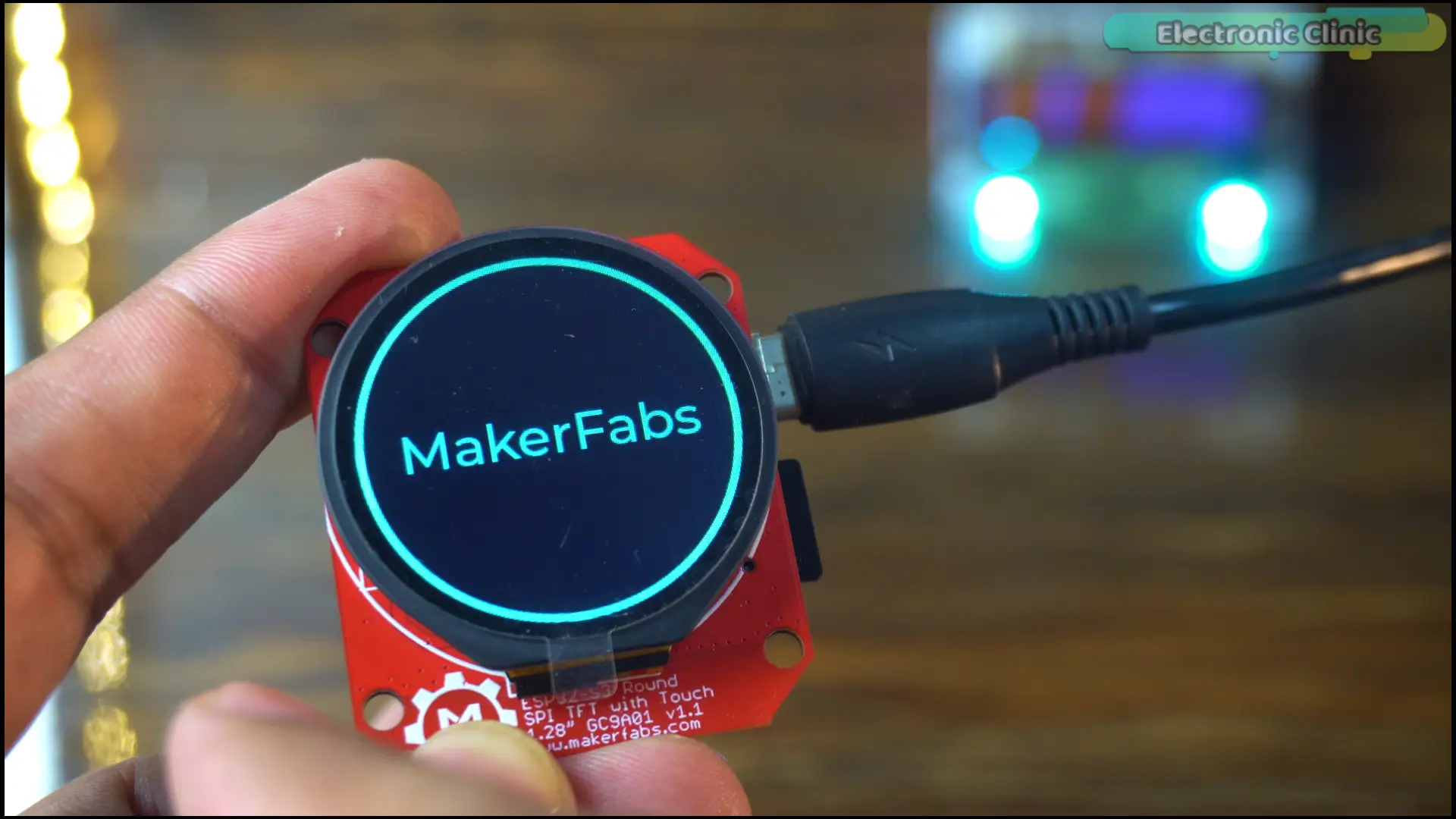
This is the foundation and it took almost no time, because the template was already configured.
Now let’s build something that actually does something.
Keep watching because the next part is where the real engineering starts.
Analog Sensor project:
Earlier I told you something caught me completely off guard while building this project.
This is it.
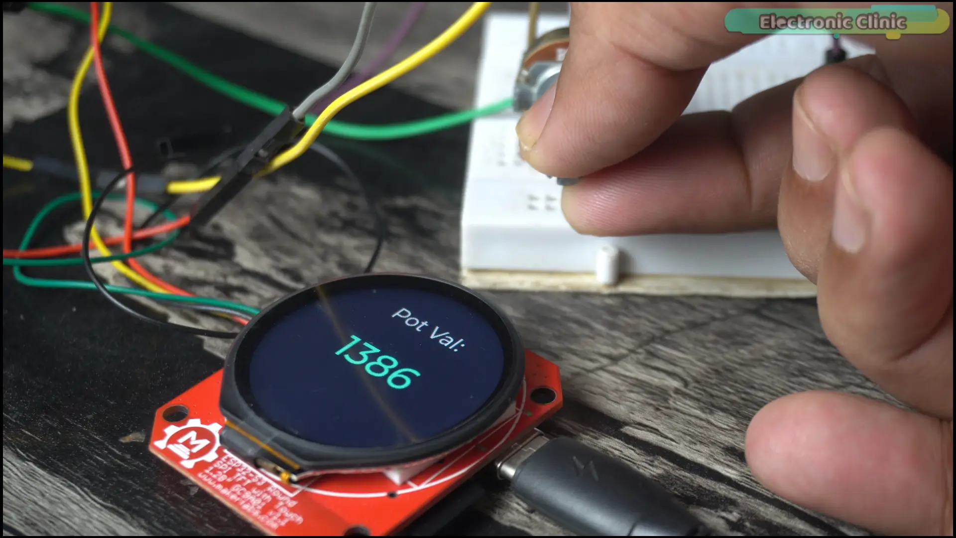
That’s a potentiometer connected to the board. I’m not touching it. Nothing is moving.
The value is jumping constantly.
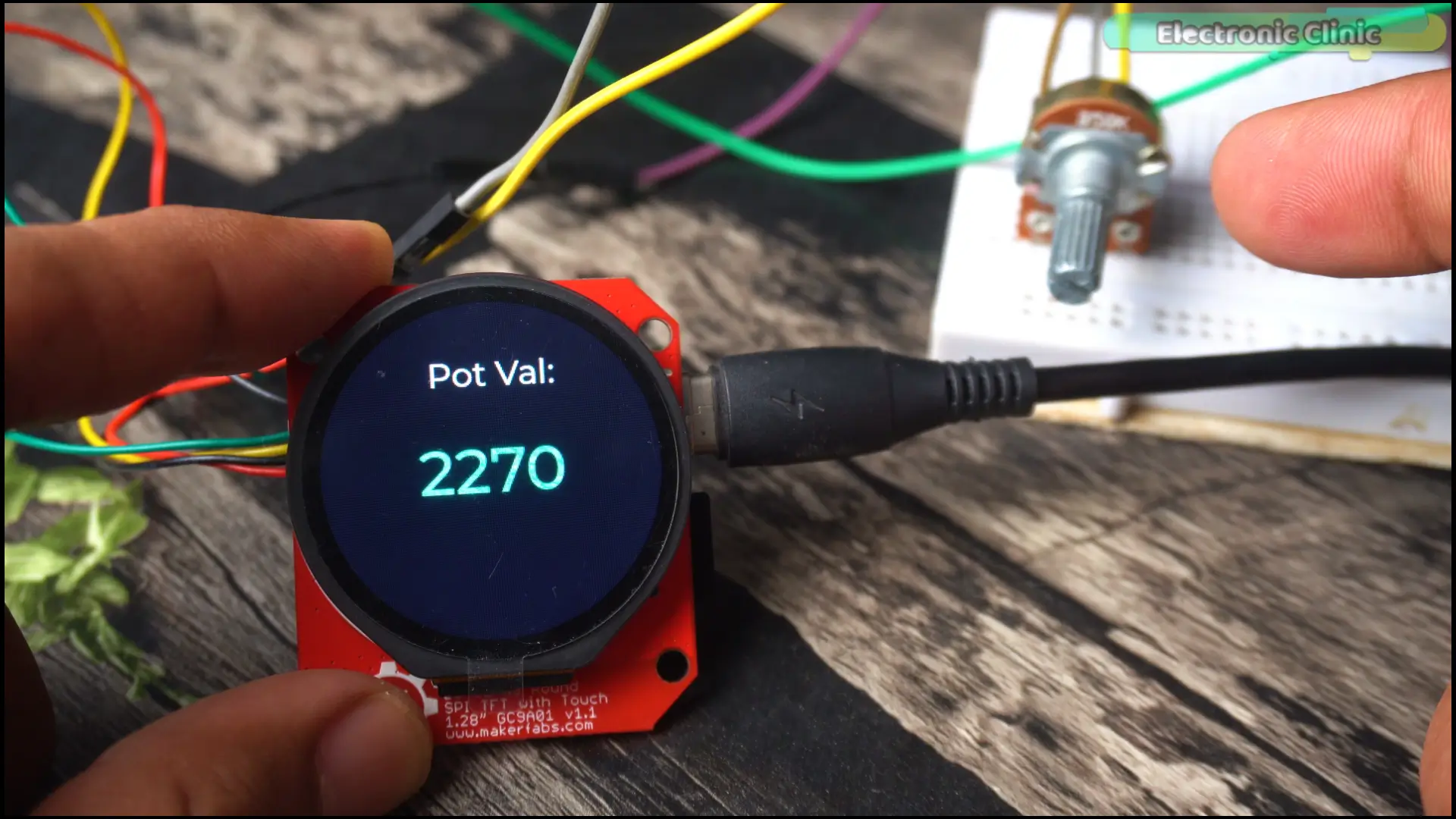
This is raw ADC output from the ESP32-S3. And on almost any microcontroller, raw analog readings behave exactly like this. Electrical noise, power supply variations, ADC inaccuracies, even interference from nearby components — all of it causes instability in the signal.
For a quick demo sitting on a desk, you might think this doesn’t matter.
But think about what you actually want to build with a display like this.
A control panel that someone else uses. A monitoring dashboard for a machine. A system that controls a motor, triggers an alarm, or makes a decision based on sensor input.
Unstable readings don’t just look bad on screen. They feed wrong data into your system. They trigger alarms that shouldn’t trigger. They make motors behave erratically. They make your project fail in the real world.
This is an engineering problem. And I’m going to show you how to solve it properly.
The fix uses three layers — two in software, one in hardware.
- Step one — Oversampling.
#define ADC_SAMPLES 32
long sum = 0;
for (int i = 0; i < ADC_SAMPLES; i++)
{
sum += analogRead(ADC_INPUT_1);
}
float sample = sum / (float)ADC_SAMPLES;
The first thing I did was take multiple ADC readings instead of relying on a single sample.
In this case, I’m taking 32 readings and calculating their average.
This immediately reduces random noise and makes the measurements much more stable.
- Exponential Moving Average (Low-Pass Filter)
#define EMA_ALPHA 0.9f
if (!ema_initialized)
{
ema_value = sample;
ema_initialized = true;
}
else
{
ema_value = EMA_ALPHA * sample +
(1.0f – EMA_ALPHA) * ema_value;
}
After averaging the samples, I pass the result through an Exponential Moving Average filter,
also known as an EMA filter. This acts like a software low-pass filter and smooths out sudden changes in the readings while still allowing the value to respond quickly when the potentiometer is moved.
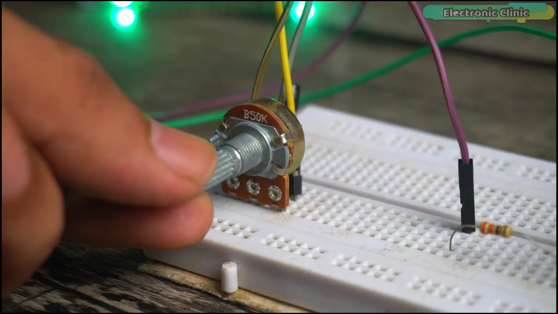
- Hysteresis (Deadband)
const int threshold = 10;
if (abs(rounded_val – displayed_val) >= threshold)
{
displayed_val = rounded_val;
lv_label_set_text_fmt(ui_lblPotValue,
“%d”,
displayed_val);
}
And finally, I added a hysteresis threshold, sometimes called a deadband.
If the ADC value changes by only a few counts, the display ignores those tiny fluctuations and keeps the previous value.
The screen only updates when the change is large enough to be meaningful.
Hardware side:
Now on the hardware side — I also added one small component.
A capacitor, placed directly across the potentiometer.
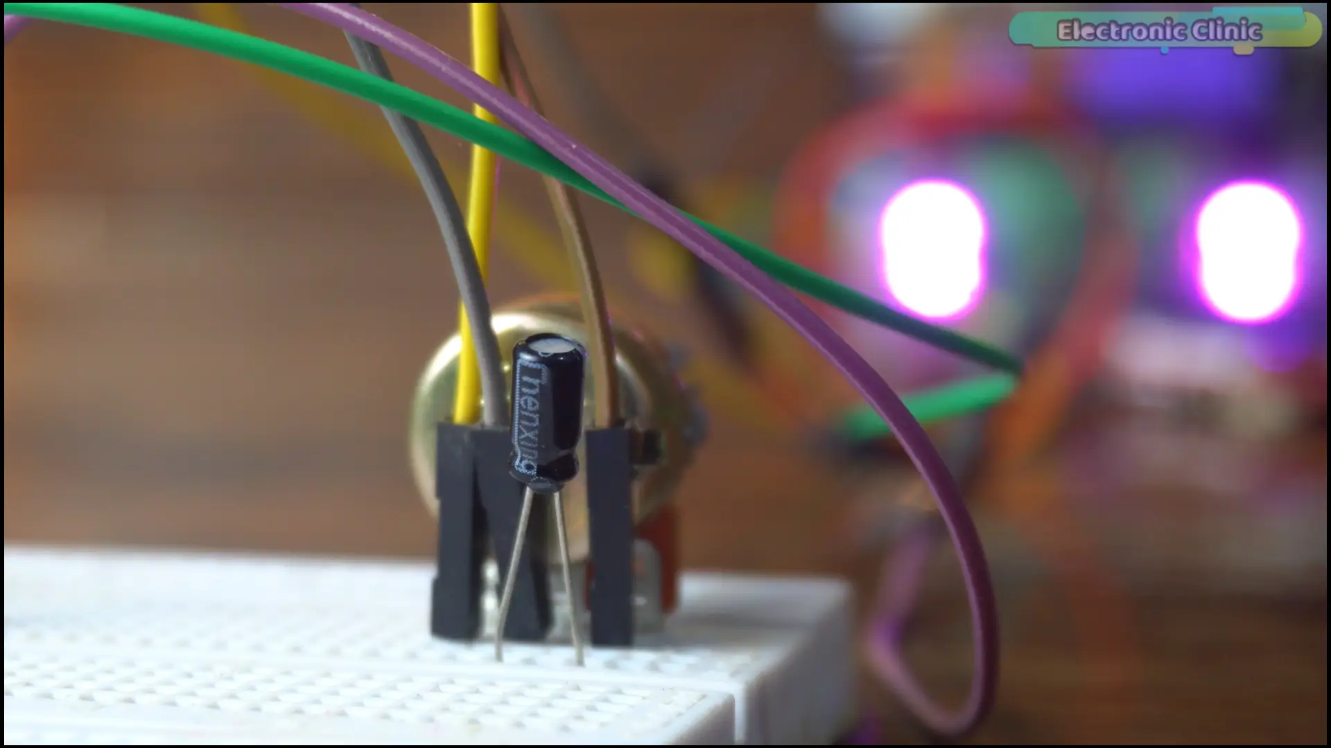
This is filtering at the source. The capacitor acts as a small energy reservoir — it absorbs rapid voltage spikes before they even reach the ESP32. It reduces the noise before the software filtering even begins.
Software filtering alone is good. Hardware filtering alone is good. Using both together is the professional approach.
Four layers of protection. One stable result.
Same potentiometer. Same board. Same conditions.
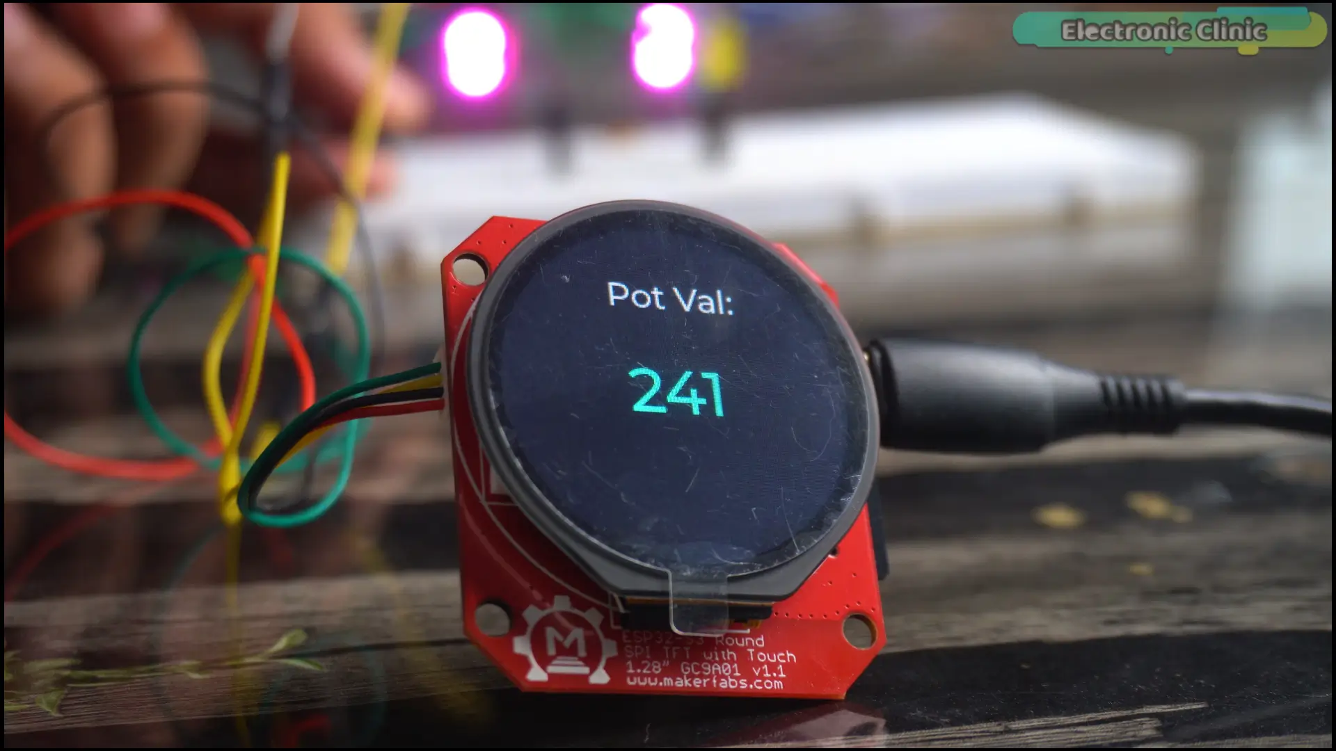
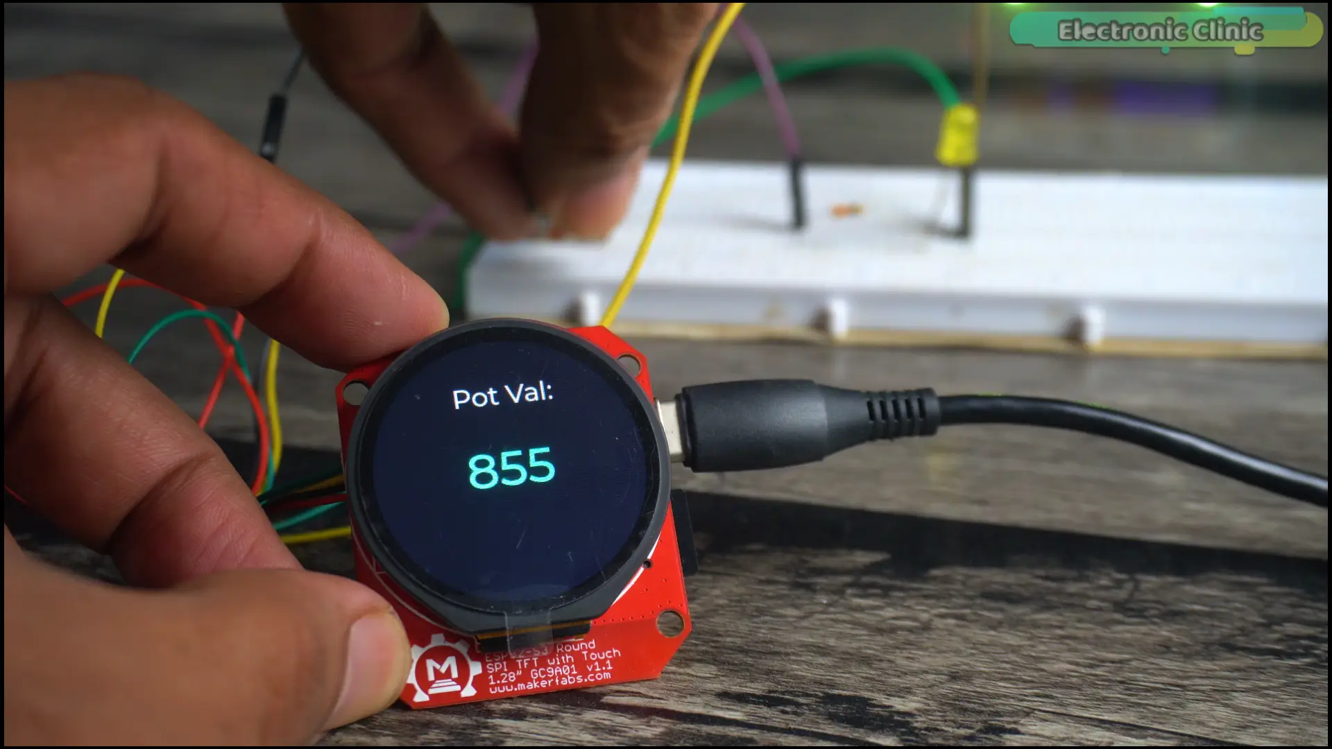
The value is now smooth, stable, and completely usable in a real application.
That’s the difference between a project that works on a desk and a project that works in the real world.
Now, let’s move on to the final project.
Final Project:
Now we bring everything together.
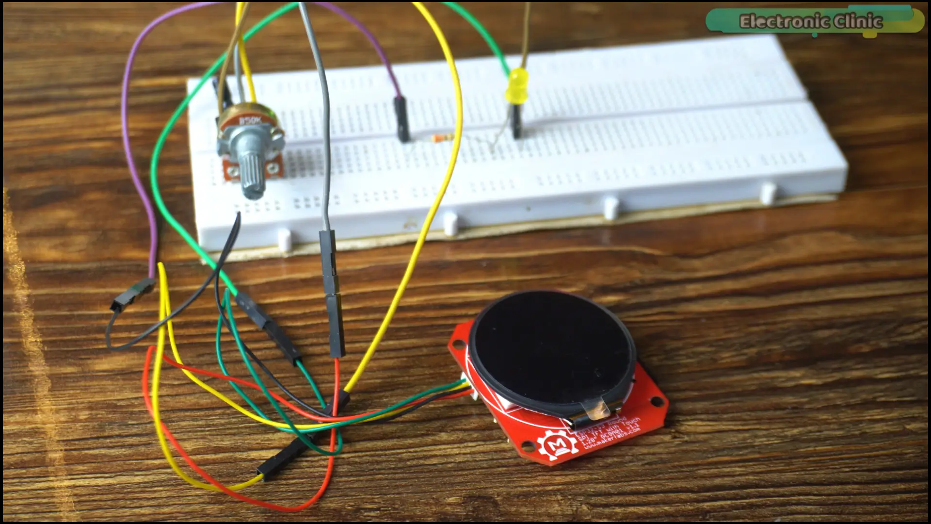
This is the final project — and this is where you’ll see exactly what becomes possible when you combine everything we’ve built.
We’re going to monitor a live sensor on one screen and control real hardware from another screen. Both running simultaneously. Both operated entirely through touch.
The sensor is connected to GPIO17.
For demonstration purposes, I’ve connected an LED to GPIO18.
In a real application, that LED could be a relay switching mains power. A MOSFET driving a motor. A solenoid. Any load you need to switch. The code stays the same. Only the load changes.
In SquareLine Studio, I’ve added a fourth screen.
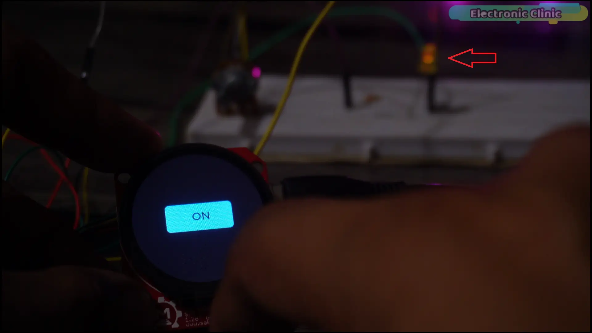
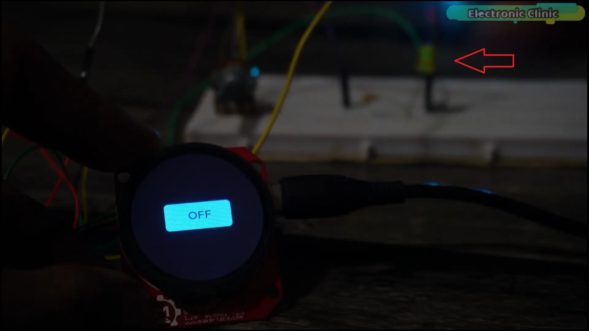
On this screen, there’s a button assigned to a function called BtnFunLED. When this button is pressed, that function runs and toggles the LED. The label on screen updates to show the current state — ON or OFF.
The other three screens remain exactly as before.
Screen one — Electronic Clinic.
Screen two — MakerFabs.
Screen three — live sensor value, smooth and stable.
Screen four — LED control. On…
Off… Status confirmed on screen.
Four screens. Live sensor input. Real hardware output.
Built from a template. Designed visually. Running on a seventeen dollar board.
This is the complete workflow.
If you want all the source code, the lv_conf.h file, the complete project template, and the SquareLine Studio files from this article — everything is available on my Patreon. The link is in the description.
And that’s everything.
Let me quickly recap what we covered today — because there’s more here than it might seem.
We set up LVGL with the exact library version and configuration that works reliably on this board. We built a reusable template that eliminates repetitive setup from every future LVGL project. We fixed a hidden color bug — the LV_COLOR_16_SWAP issue — that breaks the display on round TFTs and that most tutorials never mention. We built a three-layer noise filter that turns unstable analog readings into clean, reliable data. And we built a complete four-screen touchscreen application that monitors a live sensor and controls real hardware.
Every single one of these techniques applies directly to your next project — whatever it is.
Home automation. Industrial monitoring. IoT dashboards. Wearable devices. Custom control panels. The workflow is the same. The template is the same. And now you have both.
So, that’s all for now.
Support me on Patreon for more articles. I hope you like today’s episode. Like and share this article with your friends. See you in next episode and thanks for watching.
Support me on Patreon:
If you enjoy my work and find these projects helpful, please consider supporting me on Patreon. With just $1, you can get access to all project source codes, schematics, and extra resources that I share with my supporters. Your support helps me continue creating new electronics tutorials, experiments, and open projects for the community. Thank you so much for being part of this journey and for supporting my work!
Watch Video Tutorial:
Discover more from Electronic Clinic
Subscribe to get the latest posts sent to your email.