Sine Wave Generator using IC 741 OP AMP Operational Amplifier
Last Updated on August 20, 2022 by Engr. Shahzada Fahad
Sine Wave Generator Description:
Sine Wave Generator using IC 741 OP AMP Operational Amplifier- In this tutorial, you will learn how to make a stable Sine Wave Generator or Oscillator using IC 741 Op Amp Operational Amplifier; using a very few electronic components like resistors, capacitors, and diodes.
Before you follow the rest of the tutorial, I highly recommend reading my articles on
What is a resistor and its types?
What is capacitor and its types?
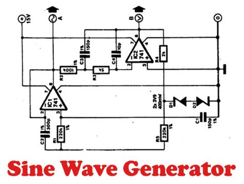
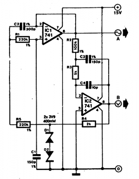
Sine Wave Generator Circuit Diagram:
The Sine Wave Generators or Oscillator normally produces an almost stable Sine wave with an output that keeps fluctuating a bit. In the circuit below the IC 741 produces the sine wave.
At 15 volts input supply, it produces 11 Volts peak to peak signal. Its output is quite stable and correct. This circuit also works perfectly at 12 volts input supply. At A and B the voltage produced is 90 degrees out of phase.
This circuit has a frequency of 3.3 kHz which can be varied using the capacitors C1, C2, and C3. If the values of the capacitors are increased 8 times, the frequency of the circuit will become 42 cycles. i.e. if the values of the capacitors are changed to
C2 = .022uf while
C1 and C3 = .01uf the Oscillator can be run on 50 cycles per second.
List of components used in the making of Sine Wave Generator:
R1, R5 = 220K ohm, ¼ watt
R2 = 100K ohm, ¼ watt
R3 = 5K ohm, ¼ watt
R4 = 2K ohm, ¼ watt
C1, C3 = 150pF
C2 = 300pF
C4 = 10pF
D1, D2 = 3.9 volt Zener diodes
IC1, IC2 = 741
Discover more from Electronic Clinic
Subscribe to get the latest posts sent to your email.


can you help me out with the directionof the zener diodes , im guessing this configuration of zener diodes is used for protection (im a noob in electronics)