A4988 Stepper Motor Driver with Arduino, NEMA17, A4988 Driver
Last Updated on August 17, 2024 by Engr. Shahzada Fahad
Table of Contents
A4988 Stepper Motor Driver, Description:
A4988 Stepper Motor Driver with Arduino- In my previous tutorial “Arduino CNC Shield V3.0 and A4988 Hybrid Stepper Motor Driver + Joystick” I used the CNC shield with Arduino and covered the maximum basic things including the technical specifications and how to use the male headers and how to use the CNC shield in custom made projects. If you are a beginner and you have never used the CNC shield then I highly recommend read my previous article which also explains how to control the speed and direction of the stepper motor automatically and then how to use a joystick to control a stepper motor.
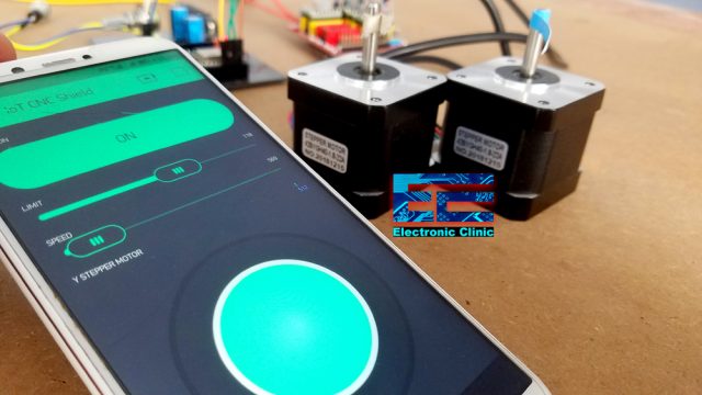
I have also used the same CNC shield with the Nodemcu ESP8266 Wifi Module this way the two Hybrid Stepper motors can be controlled from anywhere around the world using the cell phone application designed in Blynk. You will learn a lot of new things in this video, like for example, how to control the speed and limits of the stepper motor using the sliders, how to manually adjust the starting position of the stepper motor using a potentiometer, and how to control a stepper motor using the Joystick on the blynk application.
Before, I am going to explain how to make your own small size and low cost Stepper Motors controller, first a few words about the sponsor of this article.
About the Sponsor, PCBWay:
High quality & Only 24 Hours Build time
This PCB is sponsored and manufactured by the PCBway Company, which is one of the most experienced PCB and PCB assembly manufacturer. They create high-quality PCBs at reasonable prices, Only 5 dollars for 10 PCBs and 30 dollars in total for 20 PCBs assembly; besides this the new members also get a 5 Dollars bonus. As you can see the quality is really great, the silkscreen is quite clear and the black solder mask looks amazing. I am 100% satisfied with their work.
In this tutorial, you will learn how to use the most popular A4988 Stepper Motor driver with Arduino to control the NEMA17 Hybrid Stepper Motors. The reason I designed this low cost stepper motor controller is to help you easily understand the very basics so that you can design your own stepper motor controller rather than using the CNC shield. Moreover, it seems quite impractical to use the CNC shield when you need to control one or two stepper motors. There can be situations when you need to control more than 4 stepper motors, while the CNC shield can be used to control 4 stepper motors at the same time. So, in a situation like this you will need to design your own stepper motor controller. After reading this article, you will be able to control multiple stepper motors.
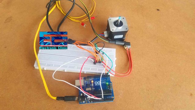
I did temporary connections on the breadboard to check my connections and codes. Initially, I started with only one stepper motor, because if you can control one stepper motor then it means you can control any number of stepper motors. While performing the tests I paid close attention to the starting and ending positions. The stepper motor returned to the same exact position from where it started.

Next, I used a potentiometer to control the speed of the Stepper Motor. This can be quite handy in places where you need to run the stepper motors at different speeds.

When I got satisfied with the result then I designed my own stepper motor controller and run the same programs to check if everything is working properly. This stepper motor controller is basically a development board which I can use to test my stepper motor based projects. I have added female headers so that other electronic components can also be easily interfaced.
Currently, this stepper motor controller can control two stepper motors at the same time, but you can easily modify this to control multiple stepper motors. I am sure, now you have got the idea, what exactly you are going to learn after reading this article.
In this tutorial we will cover,
- A4988 Stepper Motor Driver Pinout and technical specifications
- Hybrid Stepper Motor wires and technical specifications
- Complete Circuit diagram explanation
- PCB Designing and Soldering
- Interfacing and finally
- programming
Without any further delay, let’s get started!!!
Amazon Purchase Links:
Arduino Nano USB-C Type (Recommended)
24BYJ48 5V DC unipolar stepper motor:
*Disclosure: These are affiliate links. As an Amazon Associate I earn from qualifying purchases.
A4988 Stepper Motor Driver Pinout and technical specifications
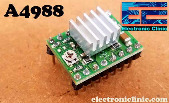
The A4988 is a complete microstepping motor driver with built-in translator for easy operation. It is designed to operate bipolar stepper motors in full-, half-, quarter-, eighth-, and sixteenth-step modes, with an output drive capacity of up to 35V and ±2A as per the datasheet. The A4988 includes a fixed off-time current regulator which has the ability to operate in Slow or Mixed decay modes.
The translator is the key to the easy implementation of the A4988. Simply inputting one pulse on the STEP input drives the motor one microstep. There are no phase sequence tables, high frequency control lines, or complex interfaces to program. The A4988 interface is an ideal fit for applications where a complex microprocessor is unavailable or is overburdened.
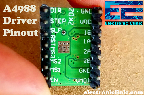
As you can the A4988 stepper motor driver has a total of 16 male headers which are clearly labeled as GND, VDD, 1B, 1A, 2B, 2A, GND, VMOT, DIR, STEP, SLP, RST, MS3, MS2, MS1, and EN.
Let’s start with the GND and VDD pins, these two pins are connected with a power supply of 3 to 5.5V to power up the driver. You can connect these two pins with the Arduino’s GND and 5V pins.
The next 4 pins 1A, 1B, 2A, and 2B are connected with the Bipolar stepper motor. As you know a Bipolar stepper motor has 4 wires which are internally connected with the two coils. So the pins 1A and 1B will be connected to one coil of the stepper motor and the pins 2A and 2B will be connected to the other coil of the Bipolar Stepper Motor.
The next two pins GND and VMOT are used to power the Bipolar Stepper Motor, the GND and VMOT pins are connected to a power supply from 8 to 35 Volts. If you are not using the CNC shield then I highly recommend to use a decoupling capacitor across these two pins, the capacitor value should be at least 47uF. This capacitor is used for protecting the A4988 driver from voltage spikes.
The next two 2 pins, Step and Direction are the pins that we actually use for controlling the motor movements. The Direction pin controls the rotation direction of the motor and we need to connect it to one of the digital pins on our microcontroller.
With the Step pin we control the mirosteps of the motor and with each pulse sent to this pin the motor moves one step. So that means that we don’t need any complex programming, phase sequence tables, frequency control lines and so on, because the built-in translator of the A4988 Driver takes care of everything. Here we also need to mention that these 2 pins are not pulled to any voltage internally, so we should not leave them floating in our program.
The sleep pin can be used to minimize the power consumption when the motor is not in use. A logic low input on this pin puts the A4988 Stepper Motor driver in sleep mode.
The next pin is the RESET pin that sets the translator to a predefined Home state. If you want to study more about this you can download the A4988 driver datasheet by clicking on the download button given below.
The next 3 pins (MS1, MS2 and MS3) are used for selecting one of the five step resolutions as per the truth table available in the datasheet.

These pins have internal pull-down resistors so if we leave them disconnected, the board will operate in full-step mode.
The last pin is the ENABLE pin which is used for turning on or turning off the FET outputs. So logic high will keep the outputs disabled.
Bipolar Stepper Motors from DFrobot:

These are the two Bipolar Stepper Motors from the DFrobot. Each stepper motor has 4 wires, Black, Red, Green, and Blue. The Black and Green wires are connected with one coil, while the Red and Blue wires are connected with the other coil.
It is a simple 2 phases hybrid stepper motor. It features 3.5kg high torque output. It is applied in most CNC machines or 3D printers such as makerbot and ultimaker. If you want to make your own CNC or 3D printer, this motor is the most suitable one.
The Model number of this Bipolar stepper motor is 42BYGH40-1.8-22A. 1.8 is the Step Angle in degrees. The rated voltage is 3.4V and the current per phase is 1.7 Amps.

The four wires of the stepper motor are provided with pins which I am going to cut and I will solder female headers so that I can easily interface the stepper motors with my designed stepper motors controller using A4988 stepper motor drivers.

So now as you can see I am done with the soldering, female headers are connected.
A4988 Stepper Motor Driver Interfacing with Arduino:

The 5V regulated Power supply based on the LM7805 voltage regulator is used to power up the Arduino Nano. J1 is the female power jack and this is where we connect the voltage source. You can connect any voltage between 8 and 25 volts. In my case, I will use 12 volts. Anyhow, the regulated 5 volts are connected with the VIN pin of the Arduino Nano.
There is also another power jack J2, you can connect any voltage between 8 and 35 volts as per your stepper motor voltage requirement. In my case I will use 12 volts. If you look closely you will find that the connections of both the A4988 Stepper motor drivers are exactly the same except the two connections. The stepper motor X, STEP and DIR pins are connected with the Arduino’s pins 2 and 3 while the Stepper Motor Y, STEP and DIR pins are connected with the Arduino’s pins 4 and 5. All the other connections remain exactly the same. Don’t forget to add a decoupling capacitor with the VMOT and GNDMOT, the capacitor can be 100uf to 470uf and the voltage should be at least double of the voltage that is used to power up the Stepper Motors.
The stepper motor is connected with the 1A, 1B, 2A, and 2B pins of the A4988 driver. The VDD pin of the A4988 driver should be connected with the Arduino’s 5V. The sleep and reset pins are connected together. Jumpers are added with the MS1, MS2, and MS3 pins. I already explained these in very detail. Finally, the enable and GND pins of the A4988 Stepper Motor Driver should be connected with the Arduino’s ground.
I have also added a Bluetooth module, which I will use to control the stepper motors using the android cell phone application. I will cover this in one of my upcoming videos.
A4988 Stepper Motor Driver Breadboard Testing:
Prior to the PCB designing, I decided to check all the connections using a breadboard. I followed the same exact connections as explained in the circuit diagram. I tested two different programs to check the performance and accuracy. In the automatic mode the stepper motor completes two rotations in the forward direction and then returns back to the starting position with great accuracy. I check it for minutes and there was no malfunction.
Next, I connected a potentiometer with the analog pin A0 to control the speed of the stepper motor. It’s a good designing practice to first check all your connections and codes before you design the final circuit or before you start the soldering. So, everything is working perfectly, now let’s take a look at the PCB layout designed in Cadsoft Eagle schematic and PCB designing software.
PCB board for the A4988 Stepper Motor Drivers and Arduino Nano:

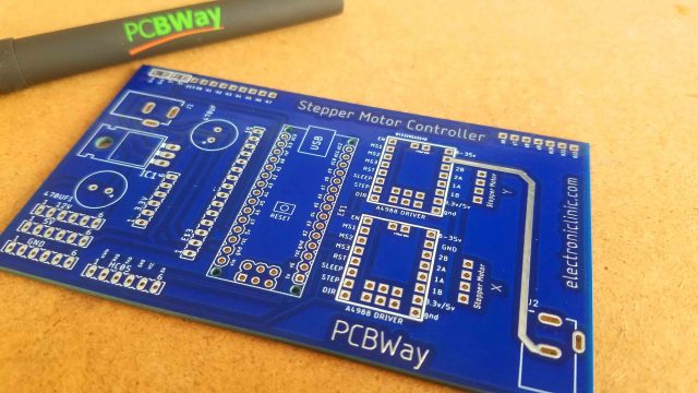
This is the PCB board I designed for controlling two stepper motors using the A4988 Stepper motor drivers. The connections are exactly as per the circuit diagram already explained. I also added female headers on the right side and left side which are connected with the power supply and i/o pins, so this way you can connect other sensors as per your requirement. I also added female headers for the 3.3V, 12V, 5V, and Gnd. I also added female headers for the HC05 Bluetooth Module, if incase you want to control the stepper motors using your android cell phone application. I will make a separate video on this. So, before generating the Gerber files I double checked all the connections, and then finally generated the Gerber files. I used the PCBWay online Gerber viewer for checking all the layers, I carefully checked the top and bottom sides. Finally, I placed an online order on the PCBWay official website.
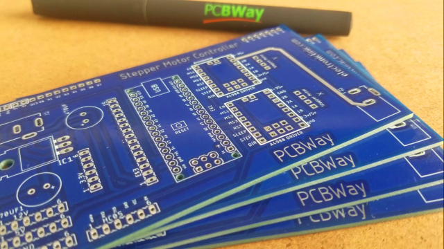
These are the PCBs I received from the PCBWay company. As you can see the quality is really great, the silkscreen is quite clear and the blue color solder mask looks amazing. Next, I started off by placing the components and complete the soldering Job.
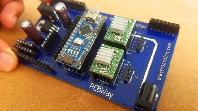
Our Stepper Motor controller is ready. I will use this as the development board for testing my stepper motor based projects. Before you power up the stepper motors first adjust the current limit, I have already explained this in my previous CNC shield based project. Finally, I connected the stepper motors with the male headers labeled as X and Y. Now let’s take a look at three different Arduino codes.
A4988 Stepper Motor Driver Arduino Programming:
|
1 2 3 4 5 6 7 8 9 10 11 12 13 14 15 16 17 18 19 20 21 22 23 24 25 26 27 28 29 30 31 32 33 |
// Stepper Motor X const int stepPin = 2; //X.STEP const int dirPin = 3; // X.DIR void setup() { // Sets the two pins as Outputs pinMode(stepPin,OUTPUT); pinMode(dirPin,OUTPUT); } void loop() { digitalWrite(dirPin,HIGH); // Enables the motor to move in a particular direction // Makes 200 pulses for making one full cycle rotation for(int x = 0; x < 400; x++) { digitalWrite(stepPin,HIGH); delayMicroseconds(500); digitalWrite(stepPin,LOW); delayMicroseconds(500); } delay(1000); // One second delay digitalWrite(dirPin,LOW); //Changes the rotations direction // Makes 400 pulses for making two full cycle rotation for(int x = 0; x < 400; x++) { digitalWrite(stepPin,HIGH); delayMicroseconds(500); digitalWrite(stepPin,LOW); delayMicroseconds(500); } delay(1000); } |
This is a very basic program which controls the steps and direction of the stepper motor. As the stepper motor I am using has the step angle of 1.8 degrees and as I am using the A4988 stepper motor driver in the full step configuration, so, for 1 complete revolution I will need 200 steps as 1.8 x 200 = 360. As you can see in the programming I am using 400, so it will complete two revolutions.
Program for controlling two stepper motors:
|
1 2 3 4 5 6 7 8 9 10 11 12 13 14 15 16 17 18 19 20 21 22 23 24 25 26 27 28 29 30 31 32 33 34 35 36 37 38 39 40 41 42 43 44 |
// Stepper Motor X const int stepPin = 2; //X.STEP const int dirPin = 3; // X.DIR // Stepper Motor Y const int stepPiny = 4; //Y.STEP const int dirPiny = 5; // Y.DIR void setup() { // Sets the two pins as Outputs pinMode(stepPin,OUTPUT); pinMode(dirPin,OUTPUT); pinMode(stepPiny,OUTPUT); pinMode(dirPiny,OUTPUT); } void loop() { digitalWrite(dirPin,HIGH); // Enables the motor to move in a particular direction digitalWrite(dirPiny,HIGH); // Enables the motor to move in a particular direction // Makes 200 pulses for making one full cycle rotation for(int x = 0; x < 400; x++) { digitalWrite(stepPin,HIGH); digitalWrite(stepPiny,HIGH); delayMicroseconds(500); digitalWrite(stepPin,LOW); digitalWrite(stepPiny,LOW); delayMicroseconds(500); } delay(1000); // One second delay digitalWrite(dirPin,LOW); //Changes the rotations direction digitalWrite(dirPiny,LOW); //Changes the rotations direction // Makes 400 pulses for making two full cycle rotation for(int x = 0; x < 400; x++) { digitalWrite(stepPin,HIGH); digitalWrite(stepPiny,HIGH); delayMicroseconds(500); digitalWrite(stepPin,LOW); digitalWrite(stepPiny,LOW); delayMicroseconds(500); } delay(1000); } |
This is the same exact program, the only modification that I did is I also defined pins for the other stepper motor. The step and direction pins of the A4988 stepper motor driver are connected with the Arduino’s pins 3 and 5. Inside the void loop function I also added instructions for controlling the direction and steps.
Stepper Motor Speed controlling using Potentiometer:
|
1 2 3 4 5 6 7 8 9 10 11 12 13 14 15 16 17 18 19 20 21 22 23 24 25 26 27 28 29 30 31 32 33 34 35 36 37 38 39 40 |
// Stepper Motor X const int stepPin = 2; //X.STEP const int dirPin = 3; // X.DIR int vresistor = A0; int vrdata; void setup() { // Sets the two pins as Outputs pinMode(stepPin,OUTPUT); pinMode(dirPin,OUTPUT); pinMode(vresistor, INPUT); } void loop() { vrdata = analogRead(vresistor); vrdata = map(vrdata,0,1023,500, 3000); digitalWrite(dirPin,HIGH); // Enables the motor to move in a particular direction // Makes 200 pulses for making one full cycle rotation for(int x = 0; x < 400; x++) { digitalWrite(stepPin,HIGH); delayMicroseconds(vrdata); digitalWrite(stepPin,LOW); delayMicroseconds(vrdata); } delay(1000); // One second delay digitalWrite(dirPin,LOW); //Changes the rotations direction // Makes 400 pulses for making two full cycle rotation for(int x = 0; x < 400; x++) { digitalWrite(stepPin,HIGH); delayMicroseconds(vrdata); digitalWrite(stepPin,LOW); delayMicroseconds(vrdata); } delay(1000); } |
This is also the same exact code, this time I added the potentiometer to control the speed. The purpose of this program is to read the potentiometer and then the value is mapped to limit the delay and then the mapped value is used as the delay. So, now by rotating the knob of the potentiometer different delays can be selected which controls the speed of the stepper motor.
For the step-by-step explanation watch the video tutorial given below. Don’t forget to subscribe to my YouTube channel. If you have any questions regarding this article, let me know in a comment.
Watch Video Tutorial:
Related Projects:
Arduino and CNC Shield getting started Tutorial
CNC Shield with Nodemcu ESP8266
CD ROM Stepper motor Arduino L298n + Joystick controlled speed and Direction Control
UniPolar and Bipolar Stepper Motors Speed and Position Control
2-Axis Joystick Arduino Project, Joystick Button & Joystick Library Arduino
Salvage Stepper Motors and other useful parts from LaserJet Printer
Discover more from Electronic Clinic
Subscribe to get the latest posts sent to your email.


