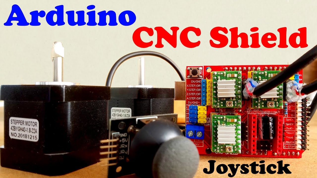
Arduino CNC Shield V3.0 and A4988 Hybrid Stepper Motor Driver + Joystick
Last Updated on May 11, 2026 by Engr. Shahzada Fahad
Table of Contents
Description:
Arduino CNC Shield V3.0 and A4988 Hybrid Stepper Motor Driver– This is a basic getting started tutorial in which you will learn how to use the Arduino CNC Shield V3.0 and A4988 Stepper Motor Driver to control a Hybrid Stepper Motor. I will start with the very basics explaining how to control the direction of the Stepper Motor using a very simple Arduino program, and then I will make it a little bit complex by adding a Joystick which can be used to control the stepper Motor. I will also explain how to use the CNC Shield male headers in custom made projects.
In this tutorial, we will cover,
- A4988 Stepper Motor Driver Pinout and technical specifications
- Arduino CNC Shield V3.0 Pinout and technical specifications
- Hybrid Stepper Motor wires and technical specifications
- Interfacing and finally
- Arduino programming
Without any further delay, let’s get started!!!
Amazon Links:
24BYJ48 5V DC unipolar stepper motor:
*Disclosure: These are affiliate links. As an Amazon Associate I earn from qualifying purchases.
What is a CNC Shield?
The Arduino CNC Shield V3.0 is a specialized expansion board (shield) that mounts directly onto an Arduino Uno. Its primary purpose is to transform the Uno into a capable multi-axis motion controller.
-
How it works: It acts as an interface that routes the Arduino’s logic pins to four stepper driver sockets (X, Y, Z, and A-axis). This allows you to control multiple stepper motors simultaneously for machines like 3D printers, laser engravers, or CNC routers.
-
GRBL Firmware: To make this shield function, you must flash GRBL firmware onto the Arduino. GRBL is an open-source “G-code interpreter” that reads instructions from your computer (e.g., “move X to 10mm”) and converts them into the precise electrical pulses needed to drive the motors.
-
Axis Assignments: The shield pre-wires the Arduino pins to match GRBL’s expected layout. The X, Y, and Z axes control standard movement, while the 4th axis (A) can be configured to mirror an existing axis (useful for dual-motor gantry setups) or act as an independent fourth axis with custom firmware.
A4988 Stepper Motor Driver Pinout and technical specifications
The A4988 is a complete microstepping motor driver with built-in translator for easy operation. It is designed to operate bipolar stepper motors in full-, half-, quarter-, eighth-, and sixteenth-step modes, with an output drive capacity of up to 35V and ±2A as per the datasheet. The A4988 includes a fixed off-time current regulator which has the ability to operate in Slow or Mixed decay modes.
The translator is the key to the easy implementation of the A4988. Simply inputting one pulse on the STEP input drives the motor one microstep. There are no phase sequence tables, high-frequency control lines, or complex interfaces to program. The A4988 interface is an ideal fit for applications where a complex microprocessor is unavailable or is overburdened.
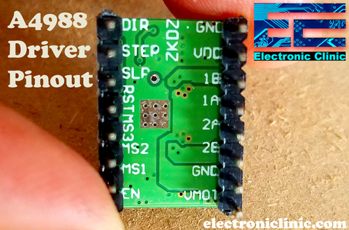
As you can the A4988 stepper motor driver has a total of 16 male headers which are clearly labeled as GND, VDD, 1B, 1A, 2B, 2A, GND, VMOT, DIR, STEP, SLP, RST, MS3, MS2, MS1, and EN.
Let’s start with the GND and VDD pins, these two pins are connected with a power supply of 3 to 5.5V to power up the driver. You can connect these two pins with the Arduino’s GND and 5V pins.
The next 4 pins 1A, 1B, 2A, and 2B are connected with the Bipolar stepper motor. As you know a Bipolar stepper motor has 4 wires which are internally connected with the two coils. So the pins 1A and 1B will be connected to one coil of the stepper motor and the pins 2A and 2B will be connected to the other coil of the Bipolar Stepper Motor.
The next two pins GND and VMOT are used to power the Bipolar Stepper Motor, the GND and VMOT pins are connected to a power supply from 8 to 35 Volts. If you are not using the CNC shield then I highly recommend to use a decoupling capacitor across these two pins, the capacitor value should be at least 47uF. This capacitor is used for protecting the A4988 driver from voltage spikes.
The next two 2 pins, Step and Direction are the pins that we actually use for controlling the motor movements. The Direction pin controls the rotation direction of the motor and we need to connect it to one of the digital pins on our microcontroller.
With the Step pin, we control the mirosteps of the motor and with each pulse sent to this pin the motor moves one step. So that means that we don’t need any complex programming, phase sequence tables, frequency control lines and so on because the built-in translator of the A4988 Driver takes care of everything. Here we also need to mention that these 2 pins are not pulled to any voltage internally, so we should not leave them floating in our program.
The sleep pin can be used to minimize power consumption when the motor is not in use. A logic low input on this pin puts the A4988 Stepper Motor driver in sleep mode.
The next pin is the RESET pin that sets the translator to a predefined Home state. If you want to study more about this you can download the A4988 driver datasheet by clicking on the download button given below.
Download A4988 Datasheet: A4988 DATASHEET
The next 3 pins (MS1, MS2, and MS3) are used for selecting one of the five step resolutions as per the truth table available in the datasheet.
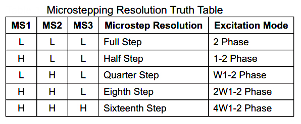
These pins have internal pull-down resistors so if we leave them disconnected, the board will operate in full step mode.
The last pin is the ENABLE pin which is used for turning on or turning off the FET outputs. So logic high will keep the outputs disabled.
CNC Shield V3.0 Pinout and Technical Specifications:
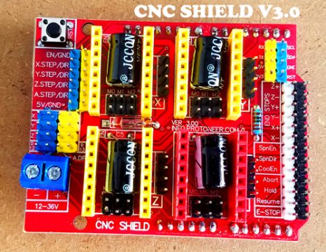
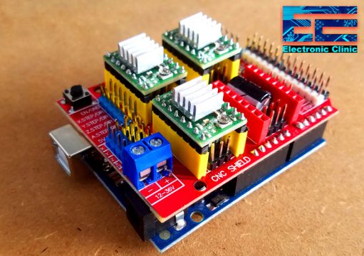
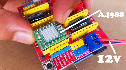
This is the Arduino CNC Shield V3.0 which I got from Digitspace.
If you have this CNC shield then using the A4988 Stepper Motor driver is very simple. You don’t need a breadboard for the connections. You can easily plug-in the A4988 drivers. You can plug-in 4 drivers. But in this tutorial, I will use only two drivers. First I will explain everything for only one driver and then later, in the end, I will use two drivers to control two stepper motors. This CNC Shield sits nicely on top of the Arduino Uno board, without any external jumper wires.
The Arduino CNC Shield makes it easy to get your CNC projects up and running in a few hours. It uses open-source firmware on Arduino to control 4 stepper motors using 4 pieces of A4988 Stepper Motor driver breakout board, with this shield and Arduino Uno/Mega, you can build all kinds of robotics, linear motion projects or projects including CNC routers, laser cutters and even pick & place machines.
You can use the open-source firmware like the GRBL that turns G-code commands into stepper signals. Which I will explain in one of my upcoming videos while making a CNC machine. But for now, in this tutorial my only goal is to help you understand how you can write your own code and how to use these male headers in custom made projects.
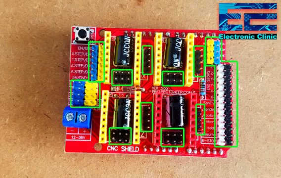
As you can see this CNC shield is provided with too many male headers. In order to use this CNC shield is custom made projects you should know about these male headers.
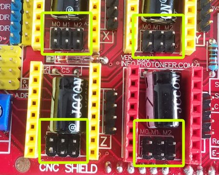
Let’s start with the male headers labeled with M0, M1, and M2. As you can see each driver is provided with jumpers that can be set to configure the microstepping for the A4988. These are connected with the driver MS1, MS2, and MS3 pins. As per the truth table, I already explained “High” indicates that a jumper is inserted and “Low” indicates that no jumper is inserted. As currently, no jumpers are inserted, so all the drivers are configured in the Full Step.
The letters X, Y, Z, and A represents the 4 stepper motors.
On the right side of each driver, you can see 4 male headers which are connected with the A4988 driver pins 1B, 1A, 2B, and 2A. This is where we connect the 4 wires of the Bipolar Stepper Motor.
A Blue color terminal block is labeled with the + and – signs and this is where we connect our external power supply. Make sure you connect the wires in the correct way otherwise you will damage the drivers.
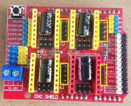
On the left side, you can see these Blue and Yellow color male headers. You will need to short the two pins labeled as EN/GND to enable the board. You can use a jumper cap or you can use female to female type jumper wire.
The X.STEP, Y.STEP, Z.STEP, and A.STEP male headers are connected with the step pins of the A4988 drivers and are also connected with the Arduino Pins which you can find by using the digital Multiplemeter. Set the multimeter on continuity or beep, when you hear the beep sound it means the two points are connected.
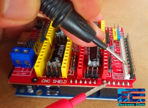
I checked all these pins and I found out that the
X.STEP is connected with the Arduino’s pin number 2.
Y.STEP is connected with the Arduino’s pin number 3.
Z.STEP is connected with the Arduino’s pin number 4.
X.DIR is connected with the Arduino’s pin number 5
Y.DIR is connected with the Arduino’s pin number 6
Z.DIR is connected with the Arduino’s pin number 7
Pin number 8 is not connected.
Pin number 9 of the Arduino is connected with the X- and X+ pins of the CNC Shield.
Pin number 10 of the Arduino is connected with the Y- and Y+ pins of the CNC Shield.
Pin number 11 of the Arduino is connected with the Z- and Z+ pins of the CNC Shield.
Pin number 12 of the Arduino is connected with the SpnEn pin of the CNC Shield.
Pin number 13 of the Arduino is connected with the SpnDir pin of the CNC Shield.
A0 analog pin of the Arduino is connected with the Abort pin of the CNC shield.
A1 analog pin of the Arduino is connected with the Hold pin of the CNC shield.
A2 analog pin of the Arduino is connected with the Resume pin of the CNC shield.
A3 analog pin of the Arduino is connected with the CoolEn pin of the CNC shield.
A4 analog pin of the Arduino is connected with the SDA pin of the CNC shield.
A5 analog pin of the Arduino is connected with the SCL pin of the CNC shield.
Bipolar Stepper Motors from DFrobot:
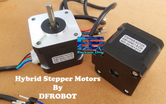
These are the two Bipolar Stepper Motors from the DFrobot. Each stepper motor has 4 wires, Black, Red, Green, and Blue. The Black and Green wires are connected with one coil, while the Red and Blue wires are connected with the other coil.
It is a simple 2 phases hybrid stepper motor. It features 3.5kg high torque output. It is applied in most CNC machines or 3D printers such as makerbot and ultimaker. If you want to make your own CNC or 3D printer, this motor is the most suitable one.
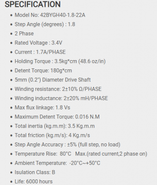
The Model number of this Bipolar stepper motor is 42BYGH40-1.8-22A. 1.8 is the Step Angle in degrees. The rated voltage is 3.4V and the current per phase is 1.7 Amps.
The four wires of the stepper motor are provided with pins which I am going to cut and I will solder female headers so that I can easily interface the stepper motors with the CNC Shield.
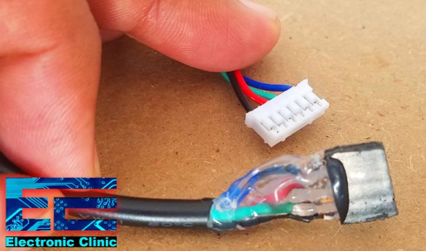
So now as you can see I am done with the soldering, female headers are connected. Now we will start the interfacing.
I started off by connecting the DC female power jack for connecting the external 12 volts power supply. Be very careful while connecting the wires, wrong connections may lead to the permanent damage of the A4988 Stepper motor drivers.
Next, plug-in the A4988 Stepper motor driver. To enable the CNC Shield short the EN and GND pins, you can use a jumper cap or you can use a female to female type jumper wire. If you find it difficult to follow, watch the video tutorial given at the end of this article.
Now before you connect the stepper motor you need to adjust the current limiting of the driver, so that we are sure that the current is within the current limits of the motor. This is done by adjusting the reference voltage using the variable resistor or potentiometer.
We have a formula for this
Current Limit = VRef x 2
As we know the Stepper motor per phase current is 1.7 Amps. So
1.7 = VRef X 2
VRef = 1.7 / 2
So
VRef = .85 Volts
After adjusting the current limit, now we can connect the stepper motor. Now the final step is to start the programming.
Arduino CNC Shield Stepper Motor Programming:
|
1 2 3 4 5 6 7 8 9 10 11 12 13 14 15 16 17 18 19 20 21 22 23 24 25 26 27 28 29 30 |
// Stepper Motor X const int stepPin = 2; //X.STEP const int dirPin = 5; // X.DIR void setup() { // Sets the two pins as Outputs pinMode(stepPin,OUTPUT); pinMode(dirPin,OUTPUT); } void loop() { digitalWrite(dirPin,HIGH); // Enables the motor to move in a particular direction // Makes 200 pulses for making one full cycle rotation for(int x = 0; x < 200; x++) { digitalWrite(stepPin,HIGH); delayMicroseconds(500); digitalWrite(stepPin,LOW); delayMicroseconds(500); } delay(1000); // One second delay digitalWrite(dirPin,LOW); //Changes the rotations direction // Makes 400 pulses for making two full cycle rotation for(int x = 0; x < 400; x++) { digitalWrite(stepPin,HIGH); delayMicroseconds(500); digitalWrite(stepPin,LOW); delayMicroseconds(500); } delay(1000); } |
This is a very basic program that controls the steps and direction of the stepper motor. As the stepper motor, I am using has a step angle of 1.8 degrees and as I am using the A4988 stepper motor driver in the full step configuration so, for 1 complete revolution I will need 200 steps as 1.8 x 200 = 360.
For the practical demonstration watch video given at the end of this article.
Now, let’s control the same stepper motor using a Joystick.
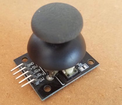
I have a very detailed tutorial on how to use this joystick.
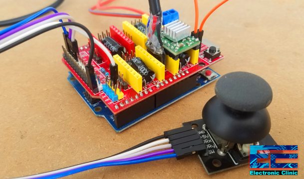
This time I added the +5v and GND pins of the Joystick with the CNC Shield 5v and ground pin and connected the VRx and VRy pins with the CNC Shield Abort and Hold pins which are connected with the Arduino’s Analog pins A0 and A1.
Arduino CNC Shield and Joystick programming:
|
1 2 3 4 5 6 7 8 9 10 11 12 13 14 15 16 17 18 19 20 21 22 23 24 25 26 27 28 29 30 31 32 33 34 35 36 37 38 39 40 41 42 43 44 45 46 47 48 49 50 51 52 53 54 55 56 57 58 59 60 61 62 63 64 65 66 67 68 69 70 71 |
// Stepper Motor X const int stepPin = 2; //X.STEP const int dirPin = 5; // X.DIR // joystick int vrx = A0; int vry = A1; int vrx_data = 0; int vry_data = 0; int x = 0; int SMSpeed = 500; // Stepper Motor Speed void setup() { // Sets the two pins as Outputs Serial.begin(9600); pinMode(stepPin,OUTPUT); pinMode(dirPin,OUTPUT); pinMode(vrx , INPUT); pinMode(vry, INPUT); } void loop() { joystick(); } void joystick() { vrx_data = analogRead(vrx); Serial.print("Vrx:"); Serial.println(vrx_data); // to stop the stepper motor if ( (vrx_data > 490) && (vrx_data < 510) ) { ; } if ( vrx_data > 700 ) { digitalWrite(dirPin,HIGH); x = x + 1; digitalWrite(stepPin,HIGH); delayMicroseconds(SMSpeed); digitalWrite(stepPin,LOW); delayMicroseconds(SMSpeed); } if ( vrx_data < 300 ) { digitalWrite(dirPin,LOW); x = x - 1; digitalWrite(stepPin,HIGH); delayMicroseconds(SMSpeed); digitalWrite(stepPin,LOW); delayMicroseconds(SMSpeed); } } |
I modified the code and defined pins for the VRx and VRy pins of the Joystick and defined two variables vrx_data and vry_data of the type integer for storing the values.
This time I defined a variable to control the stepper motor speed. I set the two pins of the joystick as the input.
Joystick() is a user-defined function. the purpose of this function is to check if the joystick is moved in the forward direction or in the reverse direction. So that’s all about the programming.
In the end, I successfully controlled the stepper motor using the Arduino CNC Shield V3.0. For the step by step explanation and demonstration, watch the video tutorial given below.
Watch Video Tutorial:
Troubleshooting — Common Problems and How to Fix Them
Problem 1: Stepper motor is not moving at all after uploading the code
Cause: The A4988 driver is not enabled, the power supply is not connected, or the driver is inserted backwards into the CNC shield.
Fix:
– Check that your motor power supply is connected to the CNC shield power terminals and turned on. The logic (Arduino) and motor power are separate — both must be connected.
– Make sure the A4988 driver is inserted in the correct orientation. The potentiometer on the A4988 should face toward the stepper motor connector side of the CNC shield. Inserting it backwards will damage the driver immediately.
– Check that you have added the 47 microfarad capacitor across the motor power supply terminals on the CNC shield. Without this capacitor, the A4988 can be destroyed by voltage spikes when the motor starts.
– In your code, make sure the Enable pin is set to LOW. The A4988 enable pin is active LOW — meaning you must write digitalWrite(enablePin, LOW) to turn the driver ON. Writing HIGH disables it.
Problem 2: Stepper motor is vibrating or buzzing but not rotating
Cause: The motor coil wires are connected in the wrong order, or the current limit on the A4988 is set too low.
Fix:
– Check your stepper motor wiring. A bipolar stepper motor has two coils — coil 1 (wires 1A and 1B) and coil 2 (wires 2A and 2B). If you mix up the wires between the two coils, the motor vibrates but does not rotate. Use a multimeter to identify the pairs — the two wires of the same coil will show continuity (low resistance, usually 2 to 10 ohms).
– Increase the current limit on the A4988 by carefully turning the small potentiometer on the driver clockwise very slightly. The current limit is set too low if the motor cannot produce enough torque to rotate.
– Make sure your motor power supply voltage is high enough for your stepper motor. Most NEMA17 motors need at least 12V to run well.
Problem 3: Stepper motor skips steps or loses position
Cause: The current limit is too low, the motor is being driven too fast, or the power supply cannot deliver enough current.
Fix:
– Increase the current limit on the A4988 potentiometer slowly. Turn it clockwise a tiny amount, test, and repeat until skipping stops. Do not exceed the current rating of your motor.
– Reduce the speed in your code by increasing the delay between step pulses. The faster you try to drive a stepper motor, the less torque it produces. Every motor has a maximum reliable speed.
– Check your power supply amperage. Each stepper motor can draw up to 2A at full load. If you are running two or three motors, make sure your supply can deliver enough total current.
– Add acceleration to your code. Abruptly starting at full speed causes step skipping. Ramp the speed up gradually at the start of each movement.
Problem 4: A4988 driver gets very hot and stops working
Cause: The current limit is set too high, or there is no heatsink on the driver chip.
Fix:
– Immediately turn off your power supply if the A4988 is burning hot. Overheating will permanently damage the chip.
– Attach the small adhesive heatsink that usually comes with A4988 drivers onto the top of the driver chip. This is almost mandatory for continuous use.
– Reduce the current limit by turning the potentiometer counterclockwise. The correct Vref voltage for your motor can be calculated using the formula: Vref = current limit x 8 x sense resistor value. For most A4988 modules with 0.1 ohm sense resistors, the formula simplifies to: Vref = motor current x 0.4.
– Enable current reduction when idle. The A4988 has a Sleep pin — connect it to a digital pin and pull it LOW when the motor is not moving. This reduces the holding current and heat significantly.
Problem 5: Motor runs in the wrong direction
Cause: The motor wiring polarity for one coil is reversed.
Fix:
– The easiest fix is to swap the two wires of either coil 1 or coil 2 — not both. For example, swap 1A and 1B positions on the motor connector. Do not swap both coils at the same time or the motor will return to the original direction.
– Alternatively, simply change the direction in your code by reversing the HIGH and LOW state of the direction pin: if you have digitalWrite(dirPin, HIGH) for forward, change it to LOW.
– On the CNC shield, each axis motor connector can also be physically flipped — remove the connector and reinsert it rotated 180 degrees.
Problem 6: The joystick controls the motor in the wrong axis or wrong direction
Cause: VRx and VRy are connected to the wrong analog pins, or the joystick center values are not being read correctly.
Fix:
– On the CNC shield, the analog pins A0 and A1 are used. Make sure VRx is connected to A0 and VRy to A1, or swap them in your code.
– The joystick resting center position outputs approximately 512 on a 10-bit ADC (range 0 to 1023). Add a dead zone in your code so the motor does not drift when the joystick is at rest. For example, only move the motor if the reading is below 400 or above 600.
– If the joystick moves the motor in the opposite direction to what you expect, simply reverse the comparison in your if statement in the code.
Problem 7: GRBL firmware not connecting or showing garbled text in serial monitor
Cause: Wrong baud rate selected in the serial monitor, or GRBL was not flashed correctly.
Fix:
– GRBL uses 115200 baud rate by default. Make sure your serial monitor is set to exactly 115200 — not 9600 or any other rate.
– If you see question marks or symbols instead of text, the baud rate is definitely wrong. Change it and reconnect.
– Use a GRBL-compatible sender software like UGS (Universal Gcode Sender) or Candle instead of the Arduino Serial Monitor for a better experience.
– If GRBL is not responding at all, re-flash it. Download the latest GRBL release from GitHub and flash it as a library using the Arduino IDE example — search for GrblUpload in File > Examples after installing the GRBL library.
Frequently Asked Questions
What is the difference between the A4988 and the DRV8825 driver?
Both are stepper motor driver modules that fit directly into the CNC shield. The main differences are: the DRV8825 supports up to 32 microstepping modes compared to 16 on the A4988, the DRV8825 can handle up to 2.2A per coil compared to 2A on the A4988, the DRV8825 runs cooler at higher currents, and the DRV8825 supports motor supply voltages up to 45V compared to 35V on the A4988. For most beginner and intermediate projects with NEMA17 motors, both work equally well. The DRV8825 is the better choice if you need more torque, higher voltage, or finer microstepping.
Can I use the CNC shield with stepper motors other than NEMA17?
Yes. The CNC shield with A4988 works with any bipolar stepper motor as long as the motor’s current rating does not exceed 2A per coil and the voltage is within the driver’s range. This includes NEMA17, NEMA23 (at lower currents), 28BYJ-48 (converted to bipolar by removing the center tap wire), CD-ROM stepper motors, and printer stepper motors. For NEMA23 motors that draw more than 2A, you need a more powerful driver such as the TB6600 or DM542 which are not compatible with the CNC shield socket.
How do I set the current limit on the A4988 correctly?
Use a multimeter set to DC voltage mode. With the motor power supply connected and the motor plugged in but not moving, place the negative probe on the GND pin of the CNC shield and the positive probe directly on the metal potentiometer shaft of the A4988 driver. The reading you get is called Vref. Calculate your target Vref using this formula: Vref = motor rated current x 0.4. For a motor rated at 1.5A, the target Vref is 0.6V. Turn the potentiometer slowly clockwise to increase Vref and counterclockwise to decrease it. Make this adjustment with the motor powered and connected but not moving.
What is microstepping and which mode should I use?
A stepper motor normally moves one full step at a time — for a standard 200 step motor this is 1.8 degrees per step. Microstepping divides each full step into smaller sub-steps for smoother and quieter motion. The A4988 supports full step, half step (400 steps per revolution), quarter step (800), eighth step (1600), and sixteenth step (3200). For CNC and 3D printing, sixteenth step (all three MS jumpers installed on the CNC shield) is the most common because it gives the smoothest motion and finest resolution. However, finer microstepping reduces torque — if your motor stalls at 1/16 step mode, try 1/8 step instead.
Can I run 4 stepper motors with one CNC shield?
Yes. The CNC shield V3.0 has 4 driver slots labeled X, Y, Z, and A. The A axis can be configured to clone any of the other axes (useful for machines that need two motors on one axis, like a dual-Y gantry) or used as an independent fourth axis with custom firmware. Note that your power supply must be able to provide enough current for all motors running simultaneously — allow at least 2A per motor for your power supply sizing.
Why does my motor lose steps when I increase speed?
Every stepper motor has a speed limit called the pull-out torque speed. Above this speed, the motor cannot produce enough torque to move the load reliably and begins skipping steps. The solution is to use acceleration — gradually ramp up speed at the start of each movement and ramp down before stopping. The AccelStepper library for Arduino makes this very easy. Also, higher voltage power supplies (within driver limits) allow higher speeds because the current can build up faster in the motor coils.
Is the CNC shield compatible with Arduino Nano or Mega?
The standard CNC shield V3.0 is designed to plug directly onto Arduino Uno. It does not physically fit an Arduino Mega or Nano without adapter boards. However, CNC shield V4.0 is specifically designed for Arduino Nano. For Arduino Mega, you would wire the A4988 drivers individually without the shield, connecting STEP and DIR pins manually. Functionally the code and wiring logic are identical — only the physical form factor is different.
Can I use this setup to build a working CNC machine or laser engraver?
Yes, this is exactly what the CNC shield and A4988 combination was designed for. To build a working CNC machine or laser engraver you need to flash GRBL firmware onto the Arduino, connect the CNC shield with three A4988 drivers for X, Y, and Z axes, wire the stepper motors and end stops, and use a GRBL sender software on your computer to send G-code commands. Many affordable desktop CNC engravers and laser cutters sold online are built on exactly this Arduino and CNC shield combination.
If you have any questions about the CNC shield or A4988 driver setup that are not covered here, leave a comment below and I will help you troubleshoot it.
Related Projects:
CD ROM Stepper motor Arduino L298n + Joystick controlled speed and Direction Control
UniPolar and Bipolar Stepper Motors Speed and Position Control
2-Axis Joystick Arduino Project, Joystick Button & Joystick Library Arduino
Salvage Stepper Motors and other useful parts from LaserJet Printer
Discover more from Electronic Clinic
Subscribe to get the latest posts sent to your email.


Hi:
Could you put the schematics for the cnc shield and joystick connection???
Thanks.
what are the changes in the code if using two motors, one for x, one for y?
Hello, how can I increase the speed of the stepper motor?
I am getting problem in making a cnc 2D plotter my steppers are not moving even I have followed all the instructions.
How can I fix this??
Hello, could you explain me how i can adjust voltage of vref? in the article you said what we have to do but I dont’t know how can i do it. thaks for your time!
what are the changes in the code if using two motors, one for x, one for y?
I really enjoyed this post! The combination of the Arduino CNC Shield V3.0 and A4988 drivers is a game-changer for DIY projects. The joystick control adds such a fun interactive element. Can’t wait to try this setup on my next project!
Great post! I love how you explained the setup process for the CNC Shield V3.0 and A4988 drivers. The joystick integration adds a fun element to controlling the CNC machine. Can’t wait to try this out on my project!
This is a fantastic overview of the Arduino CNC Shield V3.0 and the A4988 driver! I appreciate the detailed explanations and examples you provided. The joystick integration is particularly intriguing; I’m excited to try it out in my own projects. Thanks for sharing your insights!
Great post! I appreciate the detailed explanation of how to set up the Arduino CNC Shield V3.0 with the A4988 drivers. Your tips on integrating the joystick for precise control are super helpful. Can’t wait to try this on my next project!