Arduino nRF24L01 Joystick for RC Planes, Cars, Boats
Last Updated on August 16, 2024 by Engr. Shahzada Fahad
Table of Contents
Arduino nRF24L01 Joystick:
Arduino nRF24L01 Joystick for RC Planes, Cars, Boats- If you want to make a 12-channels transmitter and receiver to control RC planes, RC cars, and RC Boats using Arduino and nRF24L01, you should read this article from start to finish.

After reading this article, you will be able to control:
A BLDC motor of any rating.
The rudder.
The elevator.
The ailerons.

- With these buttons, you can set the range of servos or connect more servos to control them.
- With these switches, you can set special aerobatic maneuvers like snap rolls and flips.
I will also explain how to control a large DC motor (775) using a 320A BEC and a High Torque Servo for the steering. You can use the same setup for RC cars, RC boats, and all other radio controlled gadgets.
Additionally, if you want to establish two-way communication between your RC plane or RC car and robots, you can read my previous article. In that article, I discussed the technical specifications of the nRF24L01 transceiver module, its pinouts, how to use different baud rates, how to secure communication, and many other things. I highly recommend you should read this article Master nRF24L01.
Amazon Links:
Arduino Nano USB C type (Recommended)
nRF24L01 RF Transceiver Modules
*Disclosure: These are affiliate links. As an Amazon Associate I earn from qualifying purchases.

The transmitter and receiver are very similar in terms of connections. On both boards, I have added a 5V and 3A power supply.
For smooth operation of the nRF24L01 transceiver modules, I have also added 3.3V power supplies.
The connections for the nRF24L01 with the Arduino on both the transmitter and receiver sides are exactly the same.
You can follow this circuit diagram for the 5V and 3A power supply.

For the 3.3V power supply, use this circuit diagram. Read my articles on
how to make 5V and 3A Power Supply.
How to make a 3.3V Power supply.

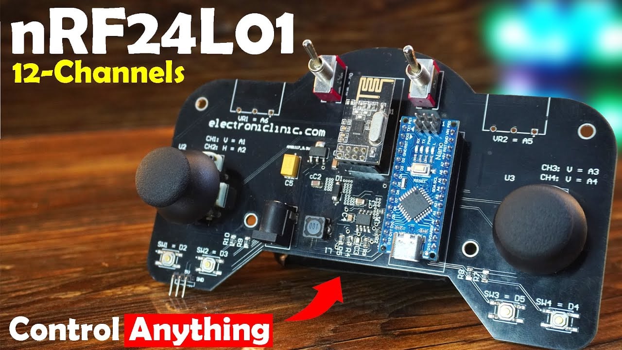
And for the connections of the 2-axis analog joysticks, nRF24L01 interfacing with the Arduino, and buttons connections, follow this circuit diagram.

You can download the Gerber files for Transmitter and Receiver Side PCBs from my Patreon page.
And send it to NextPCB for ordering high-quality PCBs at affordable prices. To check for errors in your PCB design, you can use their free online or offline HQDFM tool. NextPCB also provides component sourcing and PCB assembly services, which I discussed in my previous video on the Hydroponic System Version 1. Get $20 off if you are a new customer who has never placed an order before.
For the receiver side, start with these basic connections.

Connect only the nRF24L01 module to the Arduino at first. Because, first; we need to program the transmitter and check if it works properly. If the transmitter works fine, then we will connect the motor and servos on the receiver side.
Also, let me tell you, we will only program the transmitter side once. We will read all the components on the board and send them to the receiver side. Then, on the receiver side, we will decide whether to use the joystick data, the buttons, or all the 12 channels. Anyway, let’s go ahead and take a look at the transmitter and receiver side programs.
nRF24L01 Tx and Rx Programming:
Required Library:
RF24.h
For this, simply copy the library name, then go to the Sketch Menu, then to Include Library, and click on the Manage Libraries.

Paste the library name in the search box and as you can see; I have already installed this library.
Arduino nRF24L01 Joystick, Code:
|
1 2 3 4 5 6 7 8 9 10 11 12 13 14 15 16 17 18 19 20 21 22 23 24 25 26 27 28 29 30 31 32 33 34 35 36 37 38 39 40 41 42 43 44 45 46 47 48 49 50 51 52 53 54 55 56 57 58 59 60 61 62 63 64 65 66 67 68 69 70 71 72 73 74 75 76 77 78 79 80 81 82 83 84 85 86 87 88 89 90 91 92 93 94 95 |
/*Transmitter code pins connections vcc 3.3 gnd gnd ce pin9 scn pin10 sck pin13 mosi pin11 miso pin12 */ #include <SPI.h> #include "RF24.h" RF24 myRadio (9, 10); byte addresses[][6] = {"0"}; ///Joystick pins int v1=A1; int h1=A2; int v2=A3; int h2=A4; ///Switches pins int SW1=2; int SW2=3; int SW3=5; int SW4=4; #define SW5 0 int SW6=1; struct package { int id = 1; int v1value=0; int v2value=0; int h1value=0; int h2value=0; int S1value=0; int S2value=0; int S3value=0; int S4value=0; int S5value=0; int S6value=0; }; typedef struct package Package; Package dataTransmit; void setup() { Serial.begin(115200); pinMode(h1,INPUT); pinMode(h2,INPUT); pinMode(v1,INPUT); pinMode(v2,INPUT); pinMode(SW1,INPUT_PULLUP); pinMode(SW2,INPUT_PULLUP); pinMode(SW3,INPUT_PULLUP); pinMode(SW4,INPUT_PULLUP); pinMode(SW5,INPUT); pinMode(SW6,INPUT); myRadio.begin(); myRadio.setChannel(115); myRadio.setAutoAck(false); myRadio.setPALevel(RF24_PA_MAX); myRadio.setDataRate( RF24_250KBPS ); // for the maximum communication range //myRadio.setDataRate( RF24_2MBPS ) myRadio.openWritingPipe(addresses[0]); } void loop() { dataTransmit.id = dataTransmit.id + 1; dataTransmit.v1value = analogRead(v1); dataTransmit.v2value = analogRead(v2); dataTransmit.h1value = analogRead(h1); dataTransmit.h2value = analogRead(h2); dataTransmit.S1value = digitalRead(SW1); dataTransmit.S2value = digitalRead(SW2); dataTransmit.S3value = digitalRead(SW3); dataTransmit.S4value = digitalRead(SW4); dataTransmit.S5value = digitalRead(SW5); dataTransmit.S6value = digitalRead(SW6); Serial.println("Transmit: "); Serial.print("Package:"); Serial.print(dataTransmit.id); Serial.print("\n"); myRadio.openWritingPipe(addresses[0]); myRadio.write(&dataTransmit, sizeof(dataTransmit)); } |
Explanation:
|
1 |
RF24 myRadio (9, 10); |
This line creates an RF24 object named myRadio with CE pin connected to pin 9 and CSN pin connected to pin 10.
|
1 |
byte addresses[][6] = {"0"}; |
This is a 2D byte array to hold addresses. The address “0” is used here. To make it secure, you can use any combination of letters, numbers, and characters.
|
1 2 3 4 5 6 7 8 9 |
///Joystick pins int v1=A1; int h1=A2; int v2=A3; int h2=A4; |
The 2-axis analog joysticks are connected to the Arduino analog pins A1, A2, A3, and A4.
|
1 2 3 4 5 6 7 8 9 10 11 12 13 |
///Switches pins int SW1=2; int SW2=3; int SW3=5; int SW4=4; #define SW5 0 int SW6=1; |
All the 6 switches are connected to the Arduino pins 2, 3, 5, 4, 0, and 1.
|
1 2 3 4 5 6 7 8 9 10 11 12 13 14 15 16 17 18 19 20 21 22 23 24 25 |
struct package { int id = 1; int v1value=0; int v2value=0; int h1value=0; int h2value=0; int S1value=0; int S2value=0; int S3value=0; int S4value=0; int S5value=0; int S6value=0; }; |
Next, I defined a structure named package to hold the joystick and switch values.
|
1 |
ypedef struct package Package; |
typedef is used to create an alias Package for the struct package.
|
1 |
Package dataTransmit; |
This line creates an instance of Package named dataTransmit.
|
1 2 3 4 5 6 7 8 9 10 11 12 13 14 15 16 17 18 19 20 21 22 23 24 25 26 27 28 29 30 31 32 33 34 35 36 37 38 39 40 41 42 43 44 45 46 47 48 |
void setup() { Serial.begin(115200); pinMode(h1,INPUT); pinMode(h2,INPUT); pinMode(v1,INPUT); pinMode(v2,INPUT); pinMode(SW1,INPUT_PULLUP); pinMode(SW2,INPUT_PULLUP); pinMode(SW3,INPUT_PULLUP); pinMode(SW4,INPUT_PULLUP); pinMode(SW5,INPUT); pinMode(SW6,INPUT); myRadio.begin(); myRadio.setChannel(115); myRadio.setAutoAck(false); myRadio.setPALevel(RF24_PA_MAX); myRadio.setDataRate( RF24_250KBPS ); // for the maximum communication range //myRadio.setDataRate( RF24_2MBPS ) myRadio.openWritingPipe(addresses[0]); } |
Then inside the setup function, we simply activate the Serial communication at a baud rate of 115200.
Sets the pin modes for the joystick and switch pins to “INPUT” or “INPUT_PULLUP” as needed.
|
1 |
myRadio.begin(); |
Then we initialized the radio module.
|
1 |
myRadio.setChannel(115); |
Sets the radio communication channel to 115.
|
1 |
myRadio.setAutoAck(false); |
We disable the automatic acknowledgement feature of the radio module. Here are some advantages of doing this:
Increased Speed
Disabling automatic acknowledgment can slightly increase the speed of communication since the radio doesn’t need to wait for an acknowledgment after sending a packet.
Simpler Communication:
For very simple or one-way communication setups, automatic acknowledgment might be unnecessary. Disabling it simplifies the communication process.
Lower Power Consumption:
In certain low-power applications, avoiding the acknowledgement process can save a small amount of power, as the radio doesn’t need to listen for and process acknowledgment packets.
So, if you only need to send data in one direction and you are ok with occasional packet loss then you should disable the automatic acknowledgment feature.
|
1 |
myRadio.setPALevel(RF24_PA_MAX); |
Sets the power level of the radio to maximum.
|
1 |
myRadio.setDataRate( RF24_250KBPS ); // for the maximum communication range |
Sets the data rate to 250 kbps for maximum communication range. There are some other data rates which I have already covered in my previous video.
|
1 |
myRadio.openWritingPipe(addresses[0]); |
Opens the writing pipe with the specified address.
Then inside the loop() function, we read the analog values from the joysticks and digital values from the switch pins, and store these values in the corresponding variables. Finally, we open the writing pipe and write the “dataTransmit” structure to the radio module, sending it wirelessly to the receiver.
Now, let’s go ahead and take a look at the receiver side program.
Arduino nRF24L01 Joystick Receiver Code:
|
1 2 3 4 5 6 7 8 9 10 11 12 13 14 15 16 17 18 19 20 21 22 23 24 25 26 27 28 29 30 31 32 33 34 35 36 37 38 39 40 41 42 43 44 45 46 47 48 49 50 51 52 53 54 55 56 57 58 59 60 61 62 63 64 65 66 67 68 69 70 71 72 73 74 75 76 77 78 79 80 |
/*Receiver code pins connections vcc 3.3 gnd gnd ce pin9 scn pin10 sck pin13 mosi pin11 miso pin12 */ #include <SPI.h> #include "RF24.h" RF24 myRadio (9, 10); byte addresses[][6] = {"0"}; struct package { int id = 1; int v1value=0; int v2value=0; int h1value=0; int h2value=0; int S1value=0; int S2value=0; int S3value=0; int S4value=0; int S5value=0; int S6value=0; }; typedef struct package Package; Package dataRecieve; void setup() { Serial.begin(115200); myRadio.begin(); myRadio.setChannel(115); myRadio.setAutoAck(false); myRadio.setPALevel(RF24_PA_MAX); myRadio.setDataRate( RF24_250KBPS ); //myRadio.setDataRate( RF24_2MBPS ); myRadio.openReadingPipe(1, addresses[0]); myRadio.startListening(); } void loop() { if ( myRadio.available()) { while (myRadio.available()){ myRadio.read( &dataRecieve, sizeof(dataRecieve) ); } Serial.print("Data:"); Serial.print(dataRecieve.v1value); Serial.print(","); Serial.print(dataRecieve.v2value); Serial.print(","); Serial.print(dataRecieve.h1value); Serial.print(","); Serial.print(dataRecieve.h2value); Serial.print(","); Serial.print(dataRecieve.S1value); Serial.print(","); Serial.print(dataRecieve.S2value); Serial.print(","); Serial.print(dataRecieve.S3value); Serial.print(","); Serial.print(dataRecieve.S4value); Serial.print(","); Serial.print(dataRecieve.S5value); Serial.print(","); Serial.println(dataRecieve.S6value); } } |
Explanation:
We are using the same libraries.
|
1 |
RF24 myRadio (9, 10); |
The same CE and CSN pins on the receiver side. CE pin is connected to pin 9 and CSN pin is connected to pin 10.
|
1 |
byte addresses[][6] = {"0"}; |
The same address and structure package.
|
1 |
Package dataRecieve; |
This time we create an instance of Package named dataRecieve.
Even the code inside the setup() function is exactly the same except these two instructions.
|
1 2 3 |
myRadio.openReadingPipe(1, addresses[0]); myRadio.startListening(); |
First, we open the reading pipe and then this second instruction puts the nRF24L01 module in listening mode.
|
1 2 3 4 5 6 7 8 9 10 11 12 13 14 15 16 17 18 19 20 21 22 23 24 25 26 27 28 29 30 31 32 33 34 35 36 37 38 39 40 41 42 43 44 45 46 47 48 49 50 51 52 53 |
void loop() { if ( myRadio.available()) { while (myRadio.available()){ myRadio.read( &dataRecieve, sizeof(dataRecieve) ); } Serial.print("Data:"); Serial.print(dataRecieve.v1value); Serial.print(","); Serial.print(dataRecieve.v2value); Serial.print(","); Serial.print(dataRecieve.h1value); Serial.print(","); Serial.print(dataRecieve.h2value); Serial.print(","); Serial.print(dataRecieve.S1value); Serial.print(","); Serial.print(dataRecieve.S2value); Serial.print(","); Serial.print(dataRecieve.S3value); Serial.print(","); Serial.print(dataRecieve.S4value); Serial.print(","); Serial.print(dataRecieve.S5value); Serial.print(","); Serial.println(dataRecieve.S6value); } } |
Then inside the loop() function; we check if there is data available to read.
Continues reading as long as data is available.
Reads the received data into the dataRecieve structure.
Finally, we print all the values on the Serial monitor.
I have already uploaded these programs, so let’s go ahead and watch this in action.

Connect the Receiver to the Laptop/PC and open the Serial Monitor.
As you can see, the joysticks are working, and all the switches are working too. The control sticks are very responsive. In RC planes, we cannot afford any delay or lag. Anyway, our transmitter is completely ready, and now we can use it to control RC planes, RC cars, and other RC gadgets and robots. For the practical demonstration watch the Video Tutorial available at the end of this article.
nRF24L01 Arduino based RC Plane Setup:

This is our setup for the RC Plane. On the receiver side, I have connected one BLDC motor, the ESC signal wire is connected to the Arduino digital pin D3.
The 4 servos are connected to the Arduino pins D5, D6, D7, and D8.
If you don’t know how to install these servos on an RC Plane then you should read my article on RC Plane Designing.
For the connections you can follow this circuit diagram.

Now let’s go ahead and take a look at the receiver side program.
Arduino nRF24L01 RC Plane Arduino Code:
|
1 2 3 4 5 6 7 8 9 10 11 12 13 14 15 16 17 18 19 20 21 22 23 24 25 26 27 28 29 30 31 32 33 34 35 36 37 38 39 40 41 42 43 44 45 46 47 48 49 50 51 52 53 54 55 56 57 58 59 60 61 62 63 64 65 66 67 68 69 70 71 72 73 74 75 76 77 78 79 80 81 82 83 84 85 86 87 88 89 90 91 92 93 94 95 96 97 98 99 100 101 102 103 104 105 106 107 108 109 110 111 112 113 114 115 116 117 118 119 120 121 122 123 124 125 126 127 128 129 130 131 132 133 134 135 136 137 138 139 140 141 142 143 144 145 146 147 148 149 150 151 152 153 154 155 156 157 158 159 160 161 162 163 164 165 166 167 168 169 170 171 172 173 174 175 176 177 178 179 180 181 182 183 184 185 186 187 188 189 190 191 192 193 194 195 196 197 198 199 200 201 202 203 204 205 206 207 208 |
/*Receiver code pins connections vcc 3.3 gnd gnd ce pin9 scn pin10 sck pin13 mosi pin11 miso pin12 */ #include <SPI.h> #include "RF24.h" #include <Servo.h> // include servo library #include <Adafruit_SleepyDog.h> RF24 myRadio (9, 10); byte addresses[][6] = {"0"}; Servo elevatorServo; Servo RudderServo; Servo RightServo; Servo LeftServo; Servo BMotor; int B_Motor = 3; // Brushless Motor int Eservopin = 5; // Elevator Servo int RServopin= 6; // Rudder Servo int ServoRight=7; // int ServoLeft=8; int MyDelay = 10; struct package { int id = 1; int v1value=0; int v2value=0; int h1value=0; int h2value=0; int S1value=0; int S2value=0; int S3value=0; int S4value=0; int S5value=0; int S6value=0; }; typedef struct package Package; Package dataRecieve; void setup() { Serial.begin(115200); elevatorServo.attach(Eservopin); // pin 5 RudderServo.attach(RServopin); // pin 6 RightServo.attach(ServoRight); // pin 7 LeftServo.attach(ServoLeft); // pin 8 BMotor.attach(B_Motor, 1000, 2000);//pin 3 BMotor.write(0); elevatorServo.write(90); RudderServo.write(90); RightServo.write(90); LeftServo.write(90); myRadio.begin(); myRadio.setChannel(115); myRadio.setAutoAck(false); myRadio.setPALevel(RF24_PA_MAX); myRadio.setDataRate( RF24_250KBPS ); myRadio.openReadingPipe(1, addresses[0]); myRadio.startListening(); Watchdog.enable(1000); // 1 second } void loop() { Watchdog.reset(); if ( myRadio.available()) { while (myRadio.available()){ myRadio.read( &dataRecieve, sizeof(dataRecieve) ); } //ReceivedData(); //////////////Elevator control //Joystick 2 backward movement if (((dataRecieve.v2value) >= 0) && ((dataRecieve.v2value) <= 495)) { int EBangle = map((dataRecieve.v2value), 0, 495, 30,90); elevatorServo.write(EBangle); } //Joystick 2 Forward movement if (((dataRecieve.v2value) >= 510) && ((dataRecieve.v2value) <= 1023)) { int EFangle = map((dataRecieve.v2value), 510, 1023, 90,150); elevatorServo.write(EFangle); } //////////Rudder Control //Joystick 1 right movement if (((dataRecieve.h1value) >= 0) && ((dataRecieve.h1value) <= 495)) { int RRangle = map((dataRecieve.h1value), 0, 495, 150,90); // full 180, 150 RudderServo.write(RRangle); } //Joystick 1 left movement if (((dataRecieve.h1value) >= 510) && ((dataRecieve.h1value) <= 1023)) { int RLangle = map((dataRecieve.h1value), 510, 1023, 90,30); // change 30 into 0 if you want to move the servo arm to 0 position RudderServo.write(RLangle); } ///////////////////Aileron Control ///Joystick 2 Right movement if (((dataRecieve.h2value) >= 0) && ((dataRecieve.h2value) <= 510)) { int ASRangle1 = map((dataRecieve.h2value), 0, 510, 150,90); int ASLangle2 = map((dataRecieve.h2value), 0, 510, 150,90); RightServo.write(ASRangle1); LeftServo.write(ASLangle2); } //Joystick 2 Left movement if (((dataRecieve.h2value) >= 520) && ((dataRecieve.h2value) <= 1023)) { int ASRangle3 = map((dataRecieve.h2value), 520,1023 , 90,30); int ASLangle4 = map((dataRecieve.h2value), 520, 1023, 90,30); RightServo.write(ASRangle3); LeftServo.write(ASLangle4); } ///ESC control if (((dataRecieve.v1value) >= 510) && ((dataRecieve.h2value) <= 1023)) { int joystickValue = constrain((dataRecieve.v1value), 510, 1023); //Read upper half of joystick value from center. int motorSpeed = map(joystickValue, 510, 1023, 1000, 2000); BMotor.writeMicroseconds(motorSpeed); } // default else { // elevatorServo.write(90); // RudderServo.write(90); // RightServo.write(90); // LeftServo.write(90); //Watchdog.reset(); //delay(MyDelay); ; } } } void ReceivedData() { Serial.print("Data:"); Serial.print(dataRecieve.v1value); Serial.print(","); Serial.print(dataRecieve.v2value); Serial.print(","); Serial.print(dataRecieve.h1value); Serial.print(","); Serial.print(dataRecieve.h2value); Serial.print(","); Serial.print(dataRecieve.S1value); Serial.print(","); Serial.print(dataRecieve.S2value); Serial.print(","); Serial.print(dataRecieve.S3value); Serial.print(","); Serial.print(dataRecieve.S4value); Serial.print(","); Serial.print(dataRecieve.S5value); Serial.print(","); Serial.println(dataRecieve.S6value); } |
Explanation:
|
1 2 3 4 5 6 7 |
#include <SPI.h> #include "RF24.h" #include <Servo.h> // include servo library #include <Adafruit_SleepyDog.h> |
On the receiver side, you will also need to add these two libraries. Servo.h for controlling servos and Adafruit_SleepyDog.h for using a watchdog timer.
|
1 2 3 4 5 6 7 8 9 |
Servo elevatorServo; Servo RudderServo; Servo RightServo; Servo LeftServo; Servo BMotor; |
Create Servo objects.
|
1 2 3 4 5 6 7 8 9 |
int B_Motor = 3; // Brushless Motor int Eservopin = 5; // Elevator Servo int RServopin= 6; // Rudder Servo int ServoRight=7; // Aileron int ServoLeft=8; // Aileron |
Define pins for the BLDC motor and Servos.
Package structure remains exactly the same.
Inside the setup() function,
We activate the Serial communication, for the debugging purposes.
Attach each Servo to its respective pin.
Attach Brushless Motor to its pin.
Set all servos to the neutral position (90 degrees)
|
1 2 3 4 5 6 7 8 9 10 11 12 13 |
myRadio.begin(); myRadio.setChannel(115); myRadio.setAutoAck(false); myRadio.setPALevel(RF24_PA_MAX); myRadio.setDataRate( RF24_250KBPS ); myRadio.openReadingPipe(1, addresses[0]); myRadio.startListening(); |
This set of instructions remains exactly the same.
|
1 |
Watchdog.enable(1000); // 1 second |
Finally, set the watchdog timer.
Inside the loop() function,
Elevator Control:
If joystick 2 is moved backward (values 0-495), simply; map these values to an angle range (30-90) and set the elevator servo. If you want to move the servo arm to 0 degrees then replace 30 with 0.
If joystick 2 is moved forward (values 510-1023), map these values to an angle range (90-150) and set the elevator servo. Again, if you want to move the servo arm to 180 degrees then simply replace 150 with 180.
In the similar way, we set limits for all the other servos.
Rudder Control:
If joystick 1 is moved right (values 0-495), map these values to an angle range (150-90) and set the rudder servo.
If joystick 1 is moved left (values 510-1023), map these values to an angle range (90-30) and set the rudder servo.
Aileron Control:
If joystick 2 is moved right (values 0-510), map these values to an angle range (150-90) and set both right and left servos.
If joystick 2 is moved left (values 520-1023), map these values to an angle range (90-30) and set both right and left servos.
ESC Control:
If joystick 1’s vertical value is in the upper half (510 to 1023), map these values to a motor speed range (1000 to 2000 microseconds) and set the motor speed.
So, that’s all about the program, I have already uploaded this program, and now let’s watch the RC Plane control system in action.
Practical demonstration:

I successfully controlled the BLDC motor, Rudder Servo, Elevator Servo, and the Aileron Servos. For the practical demonstration watch the video tutorial available on my YouTube Channel “Electronic Clinic”.
Arduino nRF24L01 RC Car:

You can use this setup in RC cars, RC boats, and other RC vehicles. I have connected the 775 DC motor with a 320A BEC. I have already written a detailed article about the 775 DC motor. In that article, I also explained some other drivers along with the 320A motor driver.
Anyway, I have connected its signal wire to the Arduino digital pin D3.
With this powerful 25Kg Torque Servo, we can easily control the steering mechanism of the cars and Boats. This means that the servo can turn the wheels left or right. The high torque means it has a lot of power, so it can handle heavy loads and provide precise control, making the car steering smooth and responsive.
Anyway, its signal wire is connected to the Arduino digital pin D5. For the connections you can follow this circuit diagram.

Now, let’s go ahead and take a look at the programming.
Arduino nRF24L01 RC Car Program:
|
1 2 3 4 5 6 7 8 9 10 11 12 13 14 15 16 17 18 19 20 21 22 23 24 25 26 27 28 29 30 31 32 33 34 35 36 37 38 39 40 41 42 43 44 45 46 47 48 49 50 51 52 53 54 55 56 57 58 59 60 61 62 63 64 65 66 67 68 69 70 71 72 73 74 75 76 77 78 79 80 81 82 83 84 85 86 87 88 89 90 91 92 93 94 95 96 97 98 99 100 101 102 103 104 105 106 107 108 109 |
/*Receiver code pins connections vcc 3.3 gnd gnd ce pin9 scn pin10 sck pin13 mosi pin11 miso pin12 */ #include <SPI.h> #include "RF24.h" #include <Servo.h> // include servo library Servo BMotor; // create ESC object to control the ESC Servo Steeringservo; // create servo object to control the Servo RF24 myRadio (9, 10); byte addresses[][6] = {"0"}; int mspeed = 0; // motor speed int servoangle; struct package { int id = 1; int v1value=0; int v2value=0; int h1value=0; int h2value=0; int S1value=0; int S2value=0; int S3value=0; int S4value=0; int S5value=0; int S6value=0; }; typedef struct package Package; Package dataRecieve; void setup() { Serial.begin(115200); BMotor.attach(3);///DC Motor Steeringservo.attach(5); myRadio.begin(); myRadio.setChannel(115); myRadio.setAutoAck(false); myRadio.setPALevel(RF24_PA_MAX); myRadio.setDataRate( RF24_250KBPS ); myRadio.openReadingPipe(1, addresses[0]); myRadio.startListening(); } void loop() { if ( myRadio.available()) { while (myRadio.available()){ myRadio.read( &dataRecieve, sizeof(dataRecieve) ); } if (((dataRecieve.v1value)> 0) && ((dataRecieve.v1value) < 490)) { mspeed = map((dataRecieve.v1value), 0, 489, 2000,1501); BMotor.writeMicroseconds(mspeed); } ///Motor control if (((dataRecieve.v1value) >= 540) && ((dataRecieve.v1value) <= 1023)) { // int joystickValue = constrain((dataRecieve.v1value), 540, 1023); //Read upper half of joystick value from center. int motorSpeed = map(dataRecieve.v1value, 540, 1023, 1501, 2000); BMotor.writeMicroseconds(motorSpeed); } ///Motor stop if (((dataRecieve.v1value) >= 490) && ((dataRecieve.v1value) < 540)) { BMotor.writeMicroseconds(1500); } ///Joystick 2 Right movement if (((dataRecieve.h2value) >= 0) && ((dataRecieve.h2value) <= 510)) { int ASRangle1 = map((dataRecieve.h2value), 0, 510, 150,90); Steeringservo.write(ASRangle1); } //Joystick 2 Left movement if (((dataRecieve.h2value) >= 520) && ((dataRecieve.h2value) <= 1023)) { int ASRangle3 = map((dataRecieve.h2value), 520,1023 , 90,30); Steeringservo.write(ASRangle3); } else { ; } } } |
Explanation:
This is the same program we used for the RC plane when we were controlling the BLDC motor. But this time, we are controlling a brushed DC motor. So, I just set the range from 1501 to 2000.
|
1 |
int motorSpeed = map(dataRecieve.v1value, 540, 1023, 1501, 2000); |
Besides this, on the RC plane, we were controlling 4 servos. Whereas, this time, for the car’s steering, we are using only one servo. So, I modified the code, and now I will be able to control the car steering using the 2nd Joystick. I have already uploaded this program, so let’s watch the RC Car wireless control system in action.

It worked exceptionally well and I was amazed with the smooth operation and the responsiveness. I controlled the 775 DC Motor and the 25Kg High Torque Servo individually and also at the same time.
Support me on Patreon for more articles and videos.
Watch Video Tutorial:
Discover more from Electronic Clinic
Subscribe to get the latest posts sent to your email.


