ESP32 Lora Home Automation, Long Rage Lora Sender and Receiver, LoRa SX1278
LoRa ESP32 Home Automation Project
Last Updated on September 21, 2024 by Engr. Shahzada Fahad
Table of Contents
ESP32 LoRa Home Automation:
ESP32 Lora Home Automation, Long Rage Lora Sender and Receiver- So far I have used LoRa Transceiver modules with Arduino, Nodemcu ESP8266, and STM32 controller boards. Today, for the first time I am going to use these Long Range LoRa SX1278 Transceiver modules with ESP32 controller boards.
As you know ESP32 is much more powerful than the ESP8266 and Arduino. It is even faster than the Raspberry Pi Pico and STM32. And as you might know, ESP32 has onboard WiFi and Bluetooth and this is what makes the ESP32 much more popular than all the other controller boards.
So, in today’s article, you will learn how to make a Long range of wireless Home automation systems using ESP32 WiFi + Bluetooth modules, LoRa SX1278 Transceiver modules, 12V SPDT type relays, 110/220Vac Bulbs, and some switches.
In this project, I am using two ESP32 modules, one as the sender and the other one as the receiver.
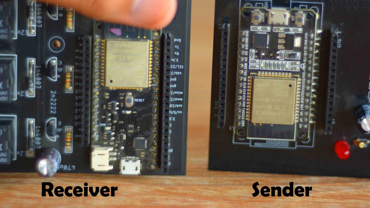
You might have noticed, that I am using two different versions of the ESP32 WiFi + Bluetooth modules. I could use the similar ESP32 modules, but the reason I am using different versions is that to explain it doesn’t matter which one of these you use; the code is going to work just fine.
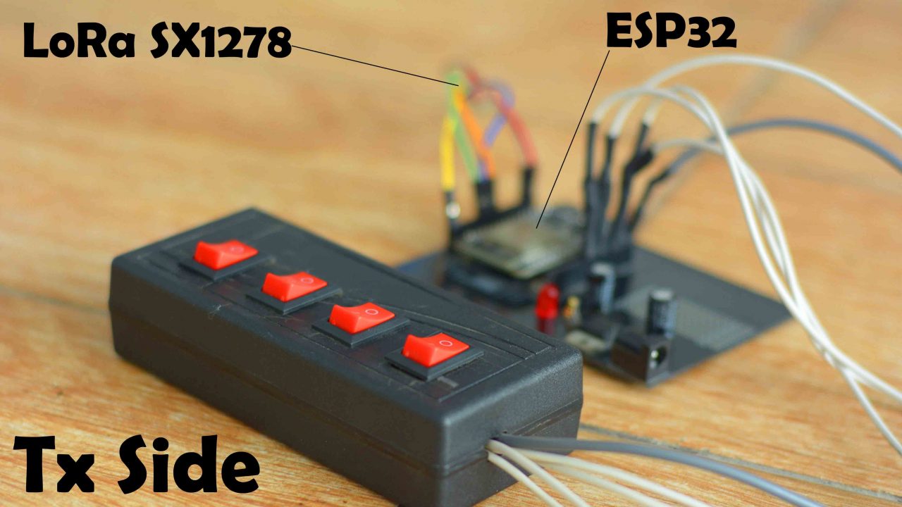
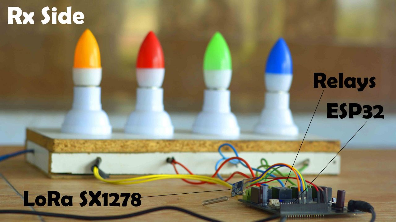
You can see 4 buttons on the transmitter side. Using these 4 buttons, I am going to control certain loads on the receiver side. For demonstration purposes, I have put 4 bulbs on the receiver’s side, which are connected to 4 relays. Besides lights, you can use any other 110/220Vac loads or use any other DC type loads.
If you want to use 110/220Vac supply, you must not forget to use protective gloves, because 110/220Vac can prove fatal. So, as far as possible you must ensure the presence of a friend or any companion while working on such projects. When the AC supply is ON, do not touch the relay contacts. Now, let’s go ahead and kick off our practical demonstration.
Practical Demonstration:
I have connected everything as per the circuit diagrams which I will explain in a minute.

Now you can see, that I have turned ON the receiver side using a 12V adaptor. And I have also connected the 220Vac. Let me remind you once again. When the 220Vac supply is connected never touch the relay contacts.

You can also use a solar panel or 12V battery to power up the ESP32 controller board as I am using 7805 Voltage regulator.

I am powering up the transmitter side through a 4S Lithium Ion Battery Pack. You may also use a 3S lipo battery pack or any other type of battery or a DC adopter for this purpose. If you also want to make such a 4S Lithium Ion battery pack, then I highly recommend read my article on 4S lithium Ion Battery Pack.
You can make the transmitter side much smaller by designing your own PCB. And you can use small toggle switches to control the AC or DC loads.
I can randomly turn ON or turn OFF any light and it is working quite superbly.

I am sure by now, you might have got an idea of how does this system work. So, without any further delay let’s get started!!!
Amazon Links:
ESP32 WiFi + Bluetooth Module(Recommended)
*Disclosure: These are affiliate links. As an Amazon Associate I earn from qualifying purchases.
SX1278 LoRa Module:
In this project, we are using the same SX-1278 LoRa modules for the transmitter and receiver. In order to use it as a receiver and transmitter, we will make changes in the code. Lora SX-1278 long-distance wireless transceiver module integrates Semtech RF transceiver chip SX1278, which adopts LoRa TM Spread Spectrum modulation frequency hopping technique. The features of long distance and high sensitivity (-139dBm) make this module perform better than FSK and GFSK modules. Multi-signal won’t affect each other even in a crowd frequency environment; it comes with strong anti-interference performance. This module is 100mW and ultra-small size, widely used in AMR, remote industrial control field.

Features:
- Frequency Range: 868 / 915 MHz
- Sensitivity up to -139dBm @Lora
- Maximum output power: 20 dBm
- 13mA@receiver mode
- Sleep current <200 nA
- Data transfer rate: @FSK,1.2-300 Kbps
- @Lora TM, 0.018-37.5 Kbps
- Lora TM, FSK, GFSK & OOK Modulation mode
- Built-in ESD Protection
- 127 dB Dynamic Range RSSI
- Packet engine up to 256 bytes with FIFO and CRC
- Hopping frequency
- Built-in temperature sensor and low battery indicator
- Excellent blocking immunity
- Operating Temperature Range:-40 ~ + 85 °C
Applications:
- Remote control
- Remote meter reading
- Home security alarm and remote keyless entry
- Industrial control
- Home automation remote sensing
- Individual data records
- Toys control
- Sensor network
- Tire pressure monitoring
- Health monitoring
- Wireless PC peripherals
- Tag reading and writing
ESP32 LoRa Home Automation Circuit Diagrams:
ESP32 LoRa Transmitter Circuit Diagram:
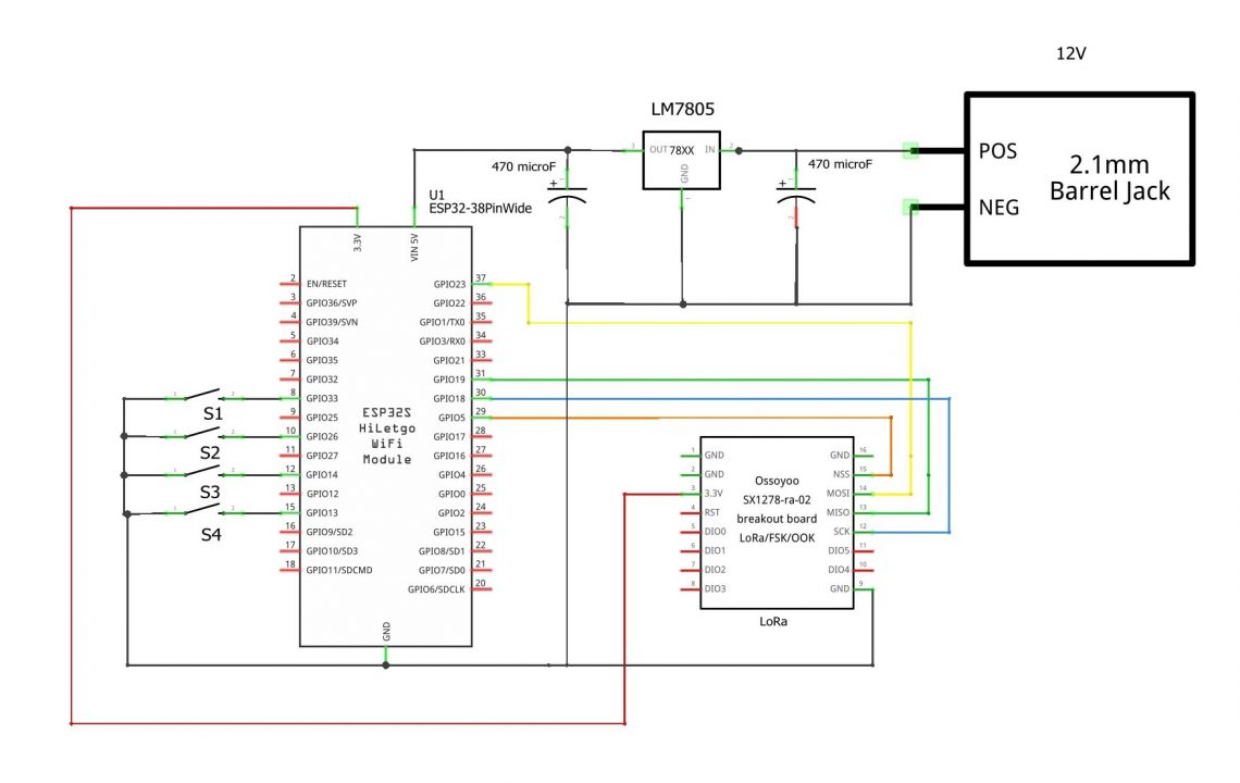
This is the transmitter side circuit diagram. I am using 5V regulated power supply based on the LM7805 linear voltage regulator. The output of the regulator is connected with the Vin pin on the ESP32 module.
The NSS pin of the LoRa module is connected with the GPIO5, the MOSI pin is connected with the GPIO23, the MISO is connected with the GPIO19, and the SCK pin of the SX1278 LoRa module is connected with the GPIO18. Make sure the ground of the ESP32 module is connected with the ground pin of the LoRa transceiver module.
On the left side you can see, 4 switches are connected with the GIPO pins 33, 26, 14, and 13. Now, let’s take a look at the receiver side circuit diagram.
ESP32 LoRa Receiver Circuit Diagram:

The connections of the 5V regulated power supply and SX1278 LoRa transceiver module remain exactly the same.
4 SPDT type relays are connected with the GPIO pins 27, 14, 12, and 13. You can connect AC or DC loads with the Relays Common and Normally Open contacts. You can also see freewheeling diodes are connected across the relays coil pins. You can use 1N4007 diodes. I am using a pair of 10K ohm and 2N2222 NPN transistor to control each relay. So, using these connections you can make your own 4-channel relay module or you can use a readymade 4-channel relay module. Read my article on how to control different types of relays.
ESP32 Home Automation Project PCBs:

These are the PCB boards which I received from the JLCPCB as you can see the quality is really great. The silkscreen is quite clear and the Black Solder mask looks amazing. Next, I started off by placing the components and completed the soldering job.
Libraries Needed:
Before, you start the programming, first of all, make sure you download the LoRa library.
You will need the LoRa library for the LoRa transceiver modules.The Adafruit_GFX and Adafruit_SSD1306 libraries are used with the Oled display module. So, if you want to display the feedback message on the Oled display then you will need these two libraries. I have added code for the feedback message.
If you are using the ESP32 WiFi + Bluetooth module for the first then you will need to know about the pinout and how to install the ESP32 board manager url link. So, I highly recommend, you guys should read my getting started tutorial on the ESP32.
ESP32 LoRa Programming:
ESP32 LoRa Tx Side Code:
|
1 2 3 4 5 6 7 8 9 10 11 12 13 14 15 16 17 18 19 20 21 22 23 24 25 26 27 28 29 30 31 32 33 34 35 36 37 38 39 40 41 42 43 44 45 46 47 48 49 50 51 52 53 54 55 56 57 58 59 60 61 62 63 64 65 66 67 68 69 70 71 72 73 74 75 76 77 78 79 80 81 82 83 84 85 86 87 88 89 90 91 92 93 94 95 96 97 98 99 100 101 102 103 104 105 106 107 108 109 110 111 112 113 114 115 116 117 118 119 120 121 122 123 124 125 126 127 128 129 130 131 132 133 134 135 136 137 138 139 140 141 142 143 144 145 146 147 148 149 150 151 152 153 154 155 156 |
<span style="font-family: georgia, palatino, serif;">/* Transmitter code ESP32 LoRa Home Automation Project by https://www.electroniclinic.com/ */ #include <SPI.h> // include libraries #include <LoRa.h> #include <Adafruit_GFX.h> #include <Adafruit_SSD1306.h> #define nss 5 #define rst 34 #define dio0 2 int sw1 = 33; int sw2 = 13; int sw3 = 14; int sw4 = 26; int Sensor1 = 0; int Sensor2 = 0; int Sensor3 = 0; int Sensor4 = 0; boolean bflag = false; String outgoing; // outgoing message byte msgCount = 0; // count of outgoing messages byte localAddress = 0xBB; // address of this device byte destination = 0xFF; // destination to send to long lastSendTime = 0; // last send time int interval = 50; // interval between sends // For Oled display #define SCREEN_WIDTH 128 // OLED display width, in pixels #define SCREEN_HEIGHT 64 // OLED display height, in pixels // Declaration for an SSD1306 display connected to I2C (SDA, SCL pins) #define OLED_RESET -1 // Reset pin # (or -1 if sharing Arduino reset pin) Adafruit_SSD1306 display(SCREEN_WIDTH, SCREEN_HEIGHT, &Wire, OLED_RESET); String Mymessage = ""; void setup() { Serial.begin(9600); // initialize serial LoRa.setPins(nss, rst, dio0); display.begin(SSD1306_SWITCHCAPVCC, 0x3C); display.clearDisplay(); display.setTextColor(WHITE); pinMode(sw1, INPUT_PULLUP); pinMode(sw2, INPUT_PULLUP); pinMode(sw3, INPUT_PULLUP); pinMode(sw4, INPUT_PULLUP); Serial.println("LoRa Duplex"); if (!LoRa.begin(433E6)) { // initialize ratio at 915 MHz Serial.println("LoRa init failed. Check your connections."); while (true); // if failed, do nothing } Serial.println("LoRa init succeeded."); } void loop() { if (millis() - lastSendTime > interval) { Sensor1 = digitalRead(sw1); delay(10); Sensor2 = digitalRead(sw2); delay(10); Sensor3 = digitalRead(sw3); delay(10); Sensor4 = digitalRead(sw4); delay(10); Mymessage = Mymessage + Sensor1 +"," + Sensor2 + "," + Sensor3 +"," + Sensor4; sendMessage(Mymessage); delay(100); Mymessage = ""; //Serial.println("Sending " + message); lastSendTime = millis(); // timestamp the message interval = random(50) + 100; } // parse for a packet, and call onReceive with the result: onReceive(LoRa.parsePacket()); } void sendMessage(String outgoing) { LoRa.beginPacket(); // start packet LoRa.write(destination); // add destination address LoRa.write(localAddress); // add sender address LoRa.write(msgCount); // add message ID LoRa.write(outgoing.length()); // add payload length LoRa.print(outgoing); // add payload LoRa.endPacket(); // finish packet and send it msgCount++; // increment message ID } void onReceive(int packetSize) { if (packetSize == 0) return; // if there's no packet, return // read packet header bytes: int recipient = LoRa.read(); // recipient address byte sender = LoRa.read(); // sender address byte incomingMsgId = LoRa.read(); // incoming msg ID byte incomingLength = LoRa.read(); // incoming msg length String incoming = ""; while (LoRa.available()) { incoming += (char)LoRa.read(); } if (incomingLength != incoming.length()) { // check length for error //Serial.println("error: message length does not match length"); ; return; // skip rest of function } // if the recipient isn't this device or broadcast, if (recipient != localAddress && recipient != 0xFF) { // Serial.println("This message is not for me."); ; return; // skip rest of function } // if message is for this device, or broadcast, print details: //Serial.println("Received from: 0x" + String(sender, HEX)); //Serial.println("Sent to: 0x" + String(recipient, HEX)); //Serial.println("Message ID: " + String(incomingMsgId)); // Serial.println("Message length: " + String(incomingLength)); Serial.println("Message: " + incoming); // Serial.println("RSSI: " + String(LoRa.packetRssi())); // Serial.println("Snr: " + String(LoRa.packetSnr())); // Serial.println(); //clear display display.clearDisplay(); display.setTextSize(2); display.setCursor(0,0); display.print("Status:"); display.setTextSize(3); display.setCursor(0, 28); display.print(incoming); display.display(); } </span> |
ESP32 LoRa Rx Side Code:
|
1 2 3 4 5 6 7 8 9 10 11 12 13 14 15 16 17 18 19 20 21 22 23 24 25 26 27 28 29 30 31 32 33 34 35 36 37 38 39 40 41 42 43 44 45 46 47 48 49 50 51 52 53 54 55 56 57 58 59 60 61 62 63 64 65 66 67 68 69 70 71 72 73 74 75 76 77 78 79 80 81 82 83 84 85 86 87 88 89 90 91 92 93 94 95 96 97 98 99 100 101 102 103 104 105 106 107 108 109 110 111 112 113 114 115 116 117 118 119 120 121 122 123 124 125 126 127 128 129 130 131 132 133 134 135 136 137 138 139 140 141 142 143 144 145 146 147 148 149 150 151 152 153 154 155 156 157 158 159 160 161 162 163 164 165 166 167 168 169 170 171 172 173 174 175 176 177 178 179 180 181 182 183 184 185 186 187 188 189 190 191 192 193 194 195 196 197 198 199 200 201 202 203 204 205 206 207 208 209 210 211 212 213 214 215 216 217 218 219 220 221 222 223 224 225 226 227 228 |
<span style="font-family: georgia, palatino, serif;">/* Receiver code ESP32 LoRa Home Automation Project by https://www.electroniclinic.com/ */ #include <SPI.h> // include libraries #include <LoRa.h> #define nss 5 #define rst 34 #define dio0 2 boolean flag1 = false; boolean flag2 = false; boolean flag3 = false; boolean flag4 = false; int RLY1=12; int RLY2=13; int RLY3=14; int RLY4=27; int Sensor1 = 0; int Sensor2 = 0; int Sensor3 = 0; int Sensor4 = 0; int relay1Status; int relay2Status; int relay3Status; int relay4Status; String outgoing; // outgoing message byte msgCount = 0; // count of outgoing messages byte localAddress = 0xFF; // address of this device byte destination = 0xBB; // destination to send to long lastSendTime = 0; // last send time int interval = 50; // interval between sends String statusmessage = ""; void setup() { Serial.begin(9600); // initialize serial pinMode(RLY1,OUTPUT); pinMode(RLY2,OUTPUT); pinMode(RLY3,OUTPUT); pinMode(RLY4,OUTPUT); LoRa.setPins(nss, rst, dio0); Serial.println("LoRa Duplex"); if (!LoRa.begin(433E6)) { // initialize ratio at 915 MHz Serial.println("LoRa init failed. Check your connections."); while (true); // if failed, do nothing } Serial.println("LoRa init succeeded."); } void loop() { if (millis() - lastSendTime > interval) { relay1Status = digitalRead(RLY1); relay2Status = digitalRead(RLY2); relay3Status = digitalRead(RLY3); relay4Status = digitalRead(RLY4); statusmessage = statusmessage + relay1Status + "," + relay2Status + "," + relay3Status + "," + relay4Status; sendMessage(statusmessage); delay(10); statusmessage = ""; lastSendTime = millis(); // timestamp the message interval = random(50) + 100; } // parse for a packet, and call onReceive with the result: onReceive(LoRa.parsePacket()); } void sendMessage(String outgoing) { LoRa.beginPacket(); // start packet LoRa.write(destination); // add destination address LoRa.write(localAddress); // add sender address LoRa.write(msgCount); // add message ID LoRa.write(outgoing.length()); // add payload length LoRa.print(outgoing); // add payload LoRa.endPacket(); // finish packet and send it msgCount++; // increment message ID } void onReceive(int packetSize) { if (packetSize == 0) return; // if there's no packet, return // read packet header bytes: int recipient = LoRa.read(); // recipient address byte sender = LoRa.read(); // sender address byte incomingMsgId = LoRa.read(); // incoming msg ID byte incomingLength = LoRa.read(); // incoming msg length String incoming = ""; while (LoRa.available()) { incoming += (char)LoRa.read(); } if (incomingLength != incoming.length()) { // check length for error // Serial.println("error: message length does not match length"); ; return; // skip rest of function } // if the recipient isn't this device or broadcast, if (recipient != localAddress && recipient != 0xFF) { //Serial.println("This message is not for me."); ; return; // skip rest of function } // if message is for this device, or broadcast, print details: // Serial.println("Received from: 0x" + String(sender, HEX)); // Serial.println("Sent to: 0x" + String(recipient, HEX)); //Serial.println("Message ID: " + String(incomingMsgId)); // Serial.println("Message length: " + String(incomingLength)); Serial.println("Message: " + incoming); //Serial.println("RSSI: " + String(LoRa.packetRssi())); //Serial.println("Snr: " + String(LoRa.packetSnr())); Serial.println(); String q = getValue(incoming, ',', 0); String r = getValue(incoming, ',', 1); String s = getValue(incoming, ',', 2); String t = getValue(incoming, ',', 3); Sensor1 = q.toInt(); Sensor2 = r.toInt(); Sensor3 = s.toInt(); Sensor4 = t.toInt(); if((Sensor1 == 0)&&(flag1==true)) { digitalWrite(RLY1,HIGH); relay1Status = 1; Serial.println("Relay 1 is turned on"); flag1=false; } if((Sensor1 == 1)&&(flag1 ==false)) { digitalWrite(RLY1,LOW); relay1Status = 0; Serial.println("Relay 1 is turned off"); flag1=true; } if((Sensor2 == 0)&&(flag2==true)) { digitalWrite(RLY2,HIGH); relay2Status = 0; Serial.println("Relay 2 is turned on"); flag2=false; } if((Sensor2 == 1)&&(flag2 ==false)) { digitalWrite(RLY2,LOW); relay2Status = 0; Serial.println("Relay 2 is turned off"); flag2=true; } if((Sensor3 == 0)&&(flag3==true)) { digitalWrite(RLY3,HIGH); relay3Status = 1; Serial.println("Relay 3 is turned on"); flag3=false; } if((Sensor3 == 1)&&(flag3 ==false)) { digitalWrite(RLY3,LOW); relay3Status = 0; Serial.println("Relay 3 is turned off"); flag3=true; } if((Sensor4 == 0)&&(flag4==true)) { digitalWrite(RLY4,HIGH); relay4Status = 1; Serial.println("Relay 4 is turned on"); flag4=false; } if((Sensor4 == 1)&&(flag4 ==false)) { digitalWrite(RLY4,LOW); relay4Status = 0; Serial.println("Relay 4 is turned off"); flag4=true; } incoming = ""; } String getValue(String data, char separator, int index) { int found = 0; int strIndex[] = { 0, -1 }; int maxIndex = data.length() - 1; for (int i = 0; i <= maxIndex && found <= index; i++) { if (data.charAt(i) == separator || i == maxIndex) { found++; strIndex[0] = strIndex[1] + 1; strIndex[1] = (i == maxIndex) ? i+1 : i; } } return found > index ? data.substring(strIndex[0], strIndex[1]) : ""; } </span> |
Actually, these codes are from my previous project based on the Arduino. I have already explained the programming. I practically demonstrated the feedback message feature, this is an important feature, when you press a button on the transmitter side, the receiver side sends you a feedback message that the desired load is turned ON or turned OFF. I also practically checked the communication range of LoRa transceiver modules. So, I highly recommend you guys need to read my previous article on Lora Home automation using Arduino, if you want to learn the most important things. Anyway.
If you don’t want the feedback message feature, then simply don’t connect the Oled display module. The code is still going to work. As in my case I am not using an Oled display. So, that’s all about the programming.
Watch Video Tutorial on YouTube

Discover more from Electronic Clinic
Subscribe to get the latest posts sent to your email.


Great project, can you please do a tutorial using this same lora method but include relay control with Blynk, so lora and Blynk together.