Raspberry Pi Pico RP2040 Programming in MicroPython with Examples
Table of Contents
Raspberry Pi Pico RP2040:
Raspberry Pi Pico RP2040 Programming in MicroPython Complete Course for Beginners with Examples– Recently I got this Raspberry Pi Pico board from the DFrobot. Raspberry Pi Pico isn’t as popular as the Arduino boards and this is because more than 80% of the guys are only running after the Arduino boards, while the fact is, Raspberry Pi Pico is the best microcontroller board and its capable of doing things, which you can’t even imagine doing with the Arduino boards. Raspberry Pi Pico is much cheaper than the Arduino Uno, Arduino Nano, and other Arduino boards. I got this Raspberry Pi Pico board from the DFrobot for only 4 dollars.
Anyway, since this is a getting started tutorial; so, I will try my level best to explain each and every detail including,
- Raspberry Pi Pico Comparison with Arduino
- Raspberry pi Pico Technical Specifications
- Raspberry Pi Pico Pinout details
- Raspberry Pi Pico Onboard Components
- Raspberry Pi Pico MicroPython installation, Driver installation, and Thonny IDE installation.
After covering the most basic things then I will practically show you how to use the most commonly used electronics components with the Raspberry Pi Pico. Since I am writing this article for the absolute beginners, so first I will start with the easiest example which is controlling the Raspberry Pi Pico onboard LED, I will write a very basic program to Turn ON and Turn OFF the Onboard LED.
Then in the 2nd example, I will show you how to connect an external LED.
In 3rd example, I will show you how to connect multiple LEDs and then how to modify the existing code to make some cool patterns. These LED example projects will help you in understanding how to turn ON and turn OFF any GPIO pin on the Raspberry Pi Pico.
In the 4th example, I will show you how to read a digital input on any GPIO pin of the Raspberry Pi Pico, for this, I will use a Pushbutton. We will be reading and controlling both at the same time. The Raspberry Pi Pico board will sense the button click and will then accordingly turn ON or turn OFF the LED.
In the 5th example, I will show you how to connect an Oled display module with the Raspberry Pi Pico. I will write a very basic program to print some text on the Oled display module. This is really an important example because in maximum of the projects you will need displays to print text and sensors values.
In the 6th example, I will show you how to use an analog sensor with the Raspberry Pi Pico and display its value on the Oled display module. For demonstration purposes, I will be using a Potentiometer as the sensor.
In the 7th example, I will show you how to use an Ultrasonic Sensor with the Raspberry Pi Pico and display its value on the Oled display module.
In the 8th example, I will show you how to make a temperature monitoring system and by the way, I will be using the Raspberry Pi Pico onboard Temperature sensor.
In the 9Th example, I will show you how to make the day and night detection system. This is really an important example as I will be explaining how to use an LDR sensor and a relay module for controlling a 110/220Vac Light Bulb.
In the 10th and final example, we will be making a small security system using a PIR sensor and a buzzer. The PIR sensor will sense the motion which will trigger the Raspberry Pi Pico and then the Raspberry Pi Pico will turn ON the buzzer.
All these Raspberry Pi Pico example projects will help you in getting started with this low-cost and powerful RP2040 based microcontroller board. So, without any further delay, let’s get started!!!
Amazon Links:
Other Tools and Components:
Super Starter kit for Beginners
PCB small portable drill machines
*Please Note: These are affiliate links. I may make a commission if you buy the components through these links. I would appreciate your support in this way!
Raspberry Pi Pico Vs Arduino:
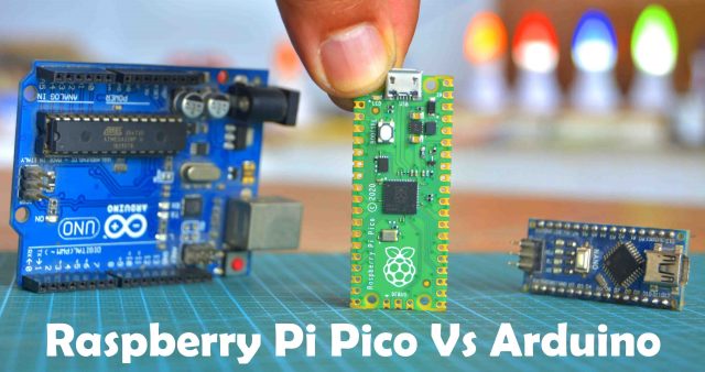
I am going to do a side by side comparison of the Raspberry Pi Pico and Arduino as this is the only way to let you know; how powerful is Raspberry Pi Pico.
| Arduino | Raspberry pi Pico | |
| Microcontroller | Atmega328p single core | RP2040 dual-core |
| Core Architecture | 8-bit RISC | 32-bit ARM cortex-MO+ |
| CPU Clock | 16MHz | 48MHz , up to 133MHz |
| RAM Size | 2 Kbyte | 264kbyte(SRAM) |
| Flash Size | 32 Kbyte | 2Mbyte(Q-SPI Flash) |
| EEPROM | 1 Kbyte | None |
| Programming | C alike Arduino IDE | Micro python, c, and c++ |
| Board power input | 5VDC via USB B | 5 VDC via USB micro B |
| Alternative Board power | 7-12 VDC via DC Socket | 1.8-5VDC via VSYS pin(pin 39) |
| MCU | 5 VDC | 3.3 VDC |
| USB interface | External USB serial IC | USB 1.1 Device and host |
| Program loading | USB B, virtual serial port | USB micro B, USB mass Storage |
| Gpio digital I/O | 20 | 26 |
| ADC | 6 x 10bit | 3 x 12 bit |
| UART | 1 | 2 |
| I2C | 1 | 2 |
| SPI | 1 | 2 |
| PWM | 6 | 16 |
| On-board led | 1 connected with D13 | 1 connected with GP25 |
| Price | USD | USD |
Arduino is based on the Atmega328 single core microcontroller while the Raspberry Pi Pico is based on the RP2040 Dual-Core.
Arduino has 8-bit Core Architecture while the Pico has 32-bit ARM Cortex M0+.
Arduino has 16MHz CPU Clock while the Pico has up to 133MHz.
RAM size on Arduino is 2 Kbyte and on Pico its 264Kbyte.
Flash size on Arduino is 32 Kbyte and on Pico its 2Mbyte.
EEPROM in Arduino is 1 Kbyte while in Pico there is no EEPROM.
Arduino programming is done in C using Arduino IDE while the Raspberry Pi Pico programming is done in Micro Python, C, and C++, and I will use Thonny IDE.
In Arduino the Board Power Input is 5Vdc which is given through USB B while in Raspberry Pi Pico the 5Vdc is supplied via USB micro B.
Alternative Board Power in Arduino is 7 to 12 volts DC which is given via DC female Socket while in Pico board the voltage range is from 1.8 to 5 volts DC which is supplied via VSYS pin 39.
Arduino is based on the 5Vdc compatible microcontroller unit while the Pico board is based on the 3.3V compatible microcontroller unit.
USB interface in Arduino is External USB serial IC and in Pico board its USB 1.1 Device and host.
Arduino uses USB B, virtual serial port for the program loading while the Pico board uses USB micro B, USB mass storage.
Arduino has 20 digital pins while Raspberry Pi Pico has 26 digital pins.
In Arduino ADC is 6x10bit while in Pico its 3x12bit.
Arduino has 1 UART and Pico has 2.
Arduino has 1 I2C and Pico has 2.
Arduino has 1 SPI and Pico has 2.
Arduino has 6 PWM pins and the Pico board has a total of 16 PWM pins.
The onboard LED in Arduino is connected to pin13 while in Raspberry Pi Pico the onboard led is connected to GP25.
The Arduino board price may vary depending on whether you are purchasing the clone version or the Genuine, But even the clone version is expensive than the Raspberry Pi Pico. On most online stores the Raspberry Pi Pico board is only 4 dollars. After this detailed comparison, I must say Raspberry Pi Pico is the future. Anyway, let’s move on to the next step which is now I am going to explain the Raspberry Pi Pico Pinout in very detail.
Altium Designer:
Altium Designer is the world’s most trusted PCB design system. Altium Designer enables engineers to effortlessly connect with every facet of the electronics design process. Over 35 years of innovation and development focused on a truly unified design environment makes it the most widely used PCB design solution. With Altium Designer you can create PCB designs with an intuitive and powerful interface that connects you to every aspect of the electronics design process. Route it your way through any angle, tune for the delay, Push, Slide, and Walkaround faster than ever. Interact and collaborate with mechanical designers like never before in a photo-realistic, 3D design environment. If you want to get started with the Altium designer, you can click on the get started.
Raspberry pi Pico specification:
The RP2040 dual-core Arm Cortex M0+ processor is used in the raspberry pi Pico. Raspberry pi Pico is very fast having 133 MHz clock frequency that we can change according to our needs. This controller has 2mb on board flashing internal space in which we can store program files.
Raspberry pi Pico Technical Specifications:
- RP2040 microcontroller chip designed by Raspberry Pi in the UK
- Dual-core ARM Cortex M0+ processor, with a flexible clock running up to 133 MHz
- 264 kB SRAM, and 2 MB on-board Flash memory
- USB 1.1 host and device support
- Energy-efficient sleep and dormant modes
- 26x multifunction GPIO pins
- 2x SPI, 2x I²C, 2x UART, 3x 12-bit ADC, 16x controllable PWM channels
- On-chip accurate clock and timer
- Temperature sensor
- On-chip accelerated floating point libraries
- 8x programmable IO (PIO) state machines for custom peripherals
Raspberry Pi Pico Pinout Explanation:
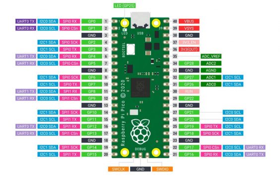
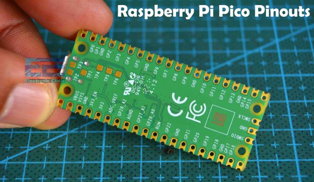
Raspberry pi Pico has a total of 40 pins or GPIOs out of which 26 GPIOs are multi-purpose. Since Raspberry Pi Pico is based on a 3.3V compatible controller board RP2040 so the operating voltage on these GPIOs should not exceed 3.3 volts. Now, out of these 26 pins, 23 pins (GPIO0 to GPIO22) are digital only and 3 pins (GPI026 to GPIO28) can either be used as digital GPIOs or as ADC inputs. Raspberry pi Pico has 2 SPI pins, 2 I2C pins, 2 UART pins, 16 Controllable PWM pins, and 9 ground pins. On the backside, you can see all the pins are clearly labeled. This board has 3 extra serial wire debug port pins.
VBUS is the micro-USB input voltage, connected to micro-USB port pin 1. This is normally 5V (or 0V if the USB is not connected or not powered).
VSYS is the main system input voltage, which can vary in the allowed range of 1.8V to 5.5V, and is used by the onboard Raspberry Pi Pico SMPS (Switched-Mode Power Supply) to generate 3.3V for the RP2040 and its GPIOs.
3V3_EN connects to the onboard SMPS enable pin and is pulled high (to VSYS) through a 100K resistor. To disable the 3.3V (which also de-powers the RP2040), short this pin low.
3V3 is the main 3.3V supply to RP2040 and its I/O pins, generated by the onboard SMPS. This pin can be used to power external circuitry (maximum output current will depend on RP2040 load and VSYS voltage, it is recommended to keep the load on this pin less than 300mA).
ADC_VREF is the ADC power supply (and reference) voltage, and is generated on Pico by filtering the 3.3V supply. This pin can be used with an external reference if better ADC performance is required.
AGND is the ground reference for GPIO26-29, there is a separate analog ground plane running under these signals and terminating at this pin. If the ADC is not used or ADC performance is not critical, this pin can be connected to a digital ground.
Now let’s take a look at the Raspberry Pi Pico onboard components.
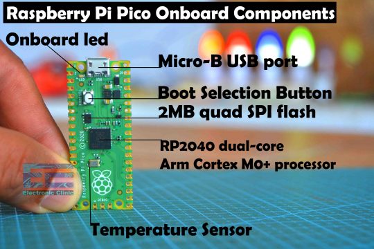
Raspberry Pi Pico Onboard Components:
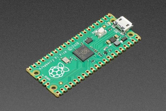
On the board you can see all the components;
- RP2040 dual-core Arm Cortex M0+ processor.
- 2MB quad SPI flash.
- Boot selection button.
- Onboard led which is connected with GP25.
- Micro-B USB port which is used for the power and also for the data transfer.
- Temperature Sensor
Now, let’s move on to the next step which is setting up the Raspberry Pi Pico before we can start the programming.
Setting up Raspberry Pi Pico:
Micro Python Installation on Raspberry Pi Pico
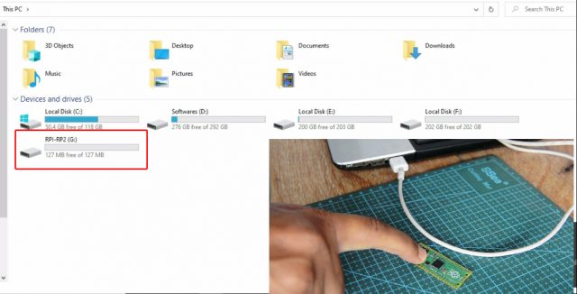
Push and hold the Boot Selection button and plug your Raspberry Pi Pico into the USB port of your Laptop or computer.
It will mount as a Mass Storage Device called RPI-RP2. Release the BOOT Selection button after your Pico is connected. Copy the MicroPython UF2 file.
Download MicroPython UF2
Once you have downloaded the MicroPython UF2 file, then simply open the RP1-RP2 device, and paste the file.
Raspberry Pi Pico Driver Installation
Next, check the driver if it’s installed; in windows 10 the driver is automatically installed, but if you are using a lower version of the windows then you will have to manually install the driver. Download the atmel_devices_cdc driver
Anyway, the driver is installed and also the MicroPython has been installed on the Raspberry Pi Pico. Now you can disconnect the Raspberry Pi Pico board.
Thonny IDE installation:
Now, the final step is to install the Thonny IDE.
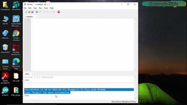
There is nothing complicated, simply follow the onscreen instructions. Once the installation is completed; open the Thonny IDE, go to the Run Menu and click on the Select interpreter.
Select MicroPython(Raspberry Pi Pico) and click on the OK button.
Now the IDE is ready for the programming.
Raspberry Pi Pico Led Blinking Example:
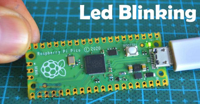
My Raspberry Pi Pico board is ready for its very first project that is blinking the Onboard LED. I am going to connect my Pico board with the Laptop. Now, let’s go ahead and take a look at the LED blinking program.
Raspberry Pi Pico Led Blinking Code:
|
1 2 3 4 5 6 7 8 9 10 |
import machine import utime led = machine.Pin(25, machine.Pin.OUT) while True: led.value(1) utime.sleep(1) led.value(0) utime.sleep(1) |
I have this very simple code for blinking the LED. The purpose of this code is to turn ON the LED for 1 second and then turn OFF the LED for 1 second. Let me explain the code.
|
1 |
import machine |
The machine module contains specific functions related to the hardware on a particular board.
|
1 |
import utime |
The utime module provides functions for getting the current time and date, measuring time intervals, and for delays.
|
1 |
led = machine.Pin(25, machine.Pin.OUT) |
The pin class has methods to set the mode of the pin (IN, OUT, etc) and methods to get and set the digital logic level.
|
1 2 3 4 5 6 7 8 9 |
while True: led.value(1) utime.sleep(1) led.value(0) utime.sleep(1) |
These lines of codes simply turn ON the Led for 1 second then turn OFF the led for 1 second. These lines of codes are executed again and again until we turn OFF the Raspberry Pi Pico board.
How to Run and Save the Code File:
To run this code on the Raspberry Pi Pico simply click on the Play button, you will be asked where to save the code file? In the computer or the Raspberry Pi Pico board, you need to select the Raspberry Pi Pico board, and the same thing I am going to do. I am going to click on the Raspberry Pi Pico.
Give a name to the file “Led_Blinking.py” and don’t forget to add the .py extension otherwise, the code won’t run on the Pico Board. As soon as you click on the OK button the LED will start blinking. The LED blinking delay time can be increased or decreased. Right now the LED is turning ON and turning OFF after every one second.
To stop the code simply click on the Stop button. For the practical demonstration watch video tutorial given at the end of this article.
When you save a file on the Raspberry Pi Pico board and you give it a name other than main.py as in my case I saved the file with the name Led_Blinking.py then such a file needs to be run manually which is really annoying. Go ahead and unplug your Raspberry Pi Pico board and then plug it again. The Led won’t work. Now, what to do, if we want to run the code automatically each time we connect the Raspberry Pi Pico board? For this you don’t have to make any changes in the code, all you need is simply resave the file but this time with the name main.py. So, if you want to run your code automatically on the Raspberry Pi Pico then give it the name main.py. Finally, click on the Ok button and you are done.
Now if you unplug your Raspberry Pi Pico board and Plug it again the code will automatically run. I am sure you have fully understood how to control the Onboard LED and how to save the code file on the Raspberry Pi Pico board. Let me remind you once again, if you face any issues then you can watch the complete video which is available at the end of this article. Anyway, you can always start with this simple getting started project to test your Raspberry Pi Pico board.
Anyway, so far everything is done correctly, the MicroPython installation is done correctly, the raspberry Pi Pico driver is working, and the Thonny IDE is working. Now, to use Pico board with external electronic devices I am going to solder male headers.
As you can see all the male headers are soldered and now, I am going to explain how to control an external LED.
External LED with Raspberry Pi Pico:
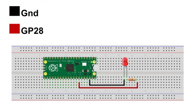
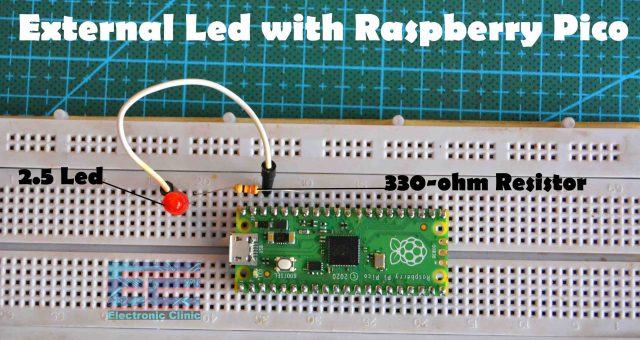
For this example, you will need a 2.5V LED and a 330-ohm resistor. So, let’s go ahead and take a look at the circuit diagram.
External Led with Raspberry Pi Pico Circuit:
The Cathode leg of the LED is connected with the Raspberry Pi Pico GND pin and the Anode leg of the LED is connected with the GP28 through a 330 ohm current limiting resistor.
I did the same exact connections on the breadboard and now let’s take a look at the programming.
Raspberry Pi Pico Led Blinking Code:
|
1 2 3 4 5 6 7 8 9 10 11 |
from machine import Pin import utime led1 =Pin(28,Pin.OUT) delay = .40 while True: led1.value(1) utime.sleep(delay) led1.value(0) utime.sleep(delay) |
This is the same exact program that I used for controlling the Onboard LED. This time I made a few changes to make it more readable. This time I am using the GP28 to control the external LED. I also defined a variable delay, so by changing this value “delay = .40” over here you can control the Blinking rate of the LED. So, let’s go ahead and run this code. Click on the play button and save the file, the same way as I previously explained.
Anyway, I uploaded the code and the LED started blinking. I am sure now you have fully understood how to control an external LED.
Multiple LEDs with Raspberry Pi Pico:
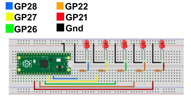
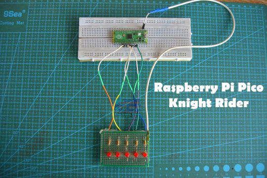
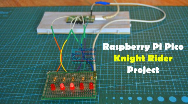
Now, in this third example, I am going to explain how to use multiple LEDs with Raspberry Pi Pico. I am going to create the Knight Rider LED effect using Raspberry Pi Pico and Multiple LEDs. So, first, let’s take a look at the circuit diagram.
Raspberry Pi Pico Knight Rider Circuit Diagram:
In the previous example, I used the GP28 pin of the Raspberry Pi Pico board to control the LED. This circuit is quite similar to the previous circuit the only difference is that this time I am using multiple LEDs. I am using the same 330-ohm current limiting resistors. The cathode legs of all the LEDs are connected with the GND pin of the Pico board and the Anode legs of all the LEDs are connected with GP21, 22, 26, 27, and 28 through these current limiting resistors. You can increase the number of LEDs as per your requirement. Make sure you keep an eye on the maximum current rating. If you need more current then you can use an external power supply.
I completed all the connections as per the circuit diagram and now let’s take a look at the programming.
Raspberry Pi Pico Knight Rider Programming:
|
1 2 3 4 5 6 7 8 9 10 11 12 13 14 15 16 17 18 19 20 21 22 23 24 25 26 27 28 29 30 31 32 33 34 35 36 37 38 39 40 41 42 43 44 45 46 47 48 49 50 51 52 53 54 55 56 57 58 59 60 61 62 63 64 65 66 67 68 69 70 71 72 73 74 75 76 77 78 79 80 81 82 83 84 85 86 87 88 89 |
from machine import Pin import utime led1 =Pin(28,Pin.OUT) led2 =Pin(27,Pin.OUT) led3 =Pin(26,Pin.OUT) led4 =Pin(22,Pin.OUT) led5 =Pin(21,Pin.OUT) delay = .06 while True: led1.value(1) led2.value(0) led3.value(0) led4.value(0) led5.value(0) utime.sleep(delay) led1.value(0) led2.value(1) led3.value(0) led4.value(0) led5.value(0) utime.sleep(delay) led1.value(0) led2.value(0) led3.value(1) led4.value(0) led5.value(0) utime.sleep(delay) led1.value(0) led2.value(0) led3.value(0) led4.value(1) led5.value(0) utime.sleep(delay) led1.value(0) led2.value(0) led3.value(0) led4.value(0) led5.value(1) utime.sleep(delay) led1.value(0) led2.value(0) led3.value(0) led4.value(0) led5.value(1) utime.sleep(delay) led1.value(0) led2.value(0) led3.value(0) led4.value(1) led5.value(0) utime.sleep(delay) led1.value(0) led2.value(0) led3.value(1) led4.value(0) led5.value(0) utime.sleep(delay) led1.value(0) led2.value(1) led3.value(0) led4.value(0) led5.value(0) utime.sleep(delay) led1.value(1) led2.value(0) led3.value(0) led4.value(0) led5.value(0) utime.sleep(delay) |
This code is similar to the previous code, the only difference is that this time I am using multiple LEDs to create the Knight Rider effect. I am turning ON only one LED at a time. You can see the code is quite lengthy, you can reduce this code to a few lines of code by using an array. For now, we will continue with this code. So, let’s go ahead and run this code.
It looks pretty awesome. You can increase or decrease the delay time in the same way as I previously explained. I am sure you have fully understood how to turn ON and turn OFF any GPIO Pin on the Raspberry Pi Pico.
You can also try this simplified code which used different GPIO pins.
|
1 2 3 4 5 6 7 8 9 10 11 12 13 14 15 16 17 18 19 20 21 22 23 24 25 26 27 28 29 30 31 32 33 34 35 |
from machine import Pin import time leds = [] for i in range(15,7,-1): leds.append(Pin(i, Pin.OUT)) sleep_time = 0.035 #50 ms #THESE list comprehensions make a list corresponding to LEDs to light #Corresponds to number of the LED in the leds list. LED_sequence = [x for x in range(0,8,1)] + [x for x in range(6,0,-1)] print(LED_sequence) #LED_sequence = [0, 1, 2, 3, 4, 5, 6, 7, 6, 5, 4, 3, 2, 1] #This is a list of "values" to apply to the LED. Turn it on, turn it off. LED_values = [1,0] while 1: for i in LED_sequence: # Loop through the sequence print(i) for value in LED_values: #Loop through the values leds[i].value(value) # For each LED, turn it on, then turn it off! time.sleep(sleep_time) # Then sleep for sleep_time |
Now, let’s move on to example4.
Raspberry Pi Pico Digital Input:
In examle4, I am going to explain how to use a Push button with the Raspberry Pi Pico. The purpose of this example is to help you understand, how to read a digital input on any GPIO pin of the Raspberry Pi Pico board. This is really an important example so make sure you don’t skip any information. If you learned how to read or detect the button click then you can read all the types of the digital sensors for example, PIR sensor, infrared obstacle sensor, Microwave Sensor, and so on. In simple words any sensor that gives you 1 or 0 as the output signal. So, in this example pushbutton is like a sensor that detects the user input.
So, to make it more interesting I am going to control an LED, so, each time the button is pressed the LED will change its state. Let’s go ahead and take a look at the circuit diagram.
Raspberry Pi Pico Push Button Circuit:
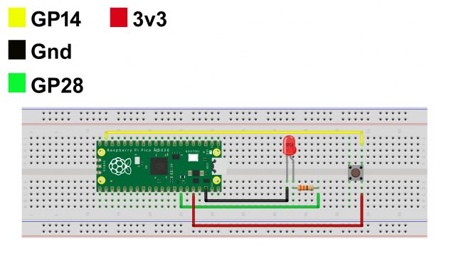
One side of the Push button is connected with 3.3V pin of the Raspberry Pi Pico while the other side of the push button is connected with GP14 pin of the Pico board.
The LED connection with the Pico Board remains exactly the same. Now, let’s take a look at the programming.
Raspberry Pi Pico Push Button Code:
|
1 2 3 4 5 6 7 8 9 10 |
from machine import Pin import time led = Pin(28, Pin.OUT) button = Pin(14, Pin.IN, Pin.PULL_DOWN) while True: if button.value(): led.toggle() time.sleep(0.5) |
The purpose of this program is to toggle the LED. As the LED is an output device so that’s why I set it as output “OUT” and as Push button is an input device so that’s why I set it as input “IN”. Reset of the code is pretty straightforward. If a button click is detected then simply toggle the LED means if the LED is OFF then turn it ON or if the LED is ON then turn it OFF. Now, let’s go ahead and run this code.
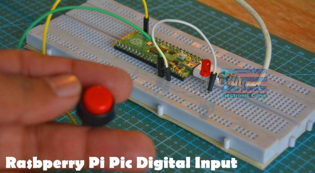
When Button is not pressed.
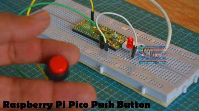
When button is pressed.
You can see each time I press the button, LED changes its state. Now, let’s move on to example5.
Raspberry Pi Pico Oled Display:
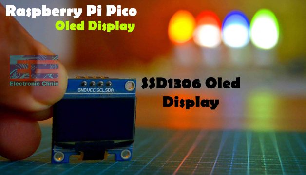
In majority of the projects we need display units for printing text and sensor values. Nowadays one of the most commonly used displays is the Oled display. The one you can see on the screen is the SSD1306 I2C supported Oled display Module which I am going to use with Raspberry Pi Pico. I have also used this Oled display module with the Arduino boards, ESP32 WiFi + Bluetooth Module, NodeMCU ESP8266 WiFi module, and so on.
Most of the Raspberry Pi Pico Oled display module libraries display text which is too small. I have seen a lot of guys searching about how to increase the text size, so in this example, I will show you how to increase the text size. But first, let’s go ahead and take a look at the circuit diagram.
SSD1306 Oled display Interfacing with Raspberry Pi Pico:
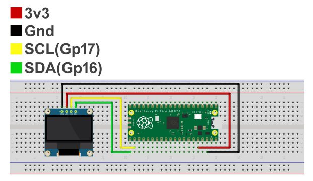
The SSD1306 Oled display module VCC and GND pins are connected with the Raspberry Pi Pico board 3.3V and GND pins. The SCL and SDA pins of the Oled Display module are connected with GP17 and GP16 pins of the Pico Board. These are the Minimal connections which you need to get started with the Oled display module.
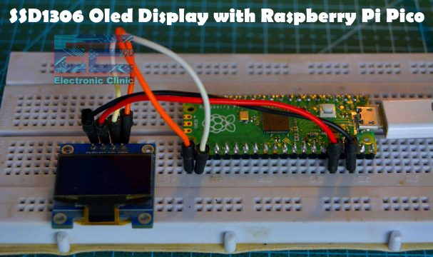
I connected the Oled display module with the Raspberry Pi Pico board as per the connection diagram. In order to display text or values on the Oled display module first we will need to install the SSD1306 library. So let’s go ahead and install the library.
Raspberry Pi Pico SSD1306 Library Installation:
Open Thonny IDE and make sure that your Thonny IDE is in Raspberry Pi Pico mode.
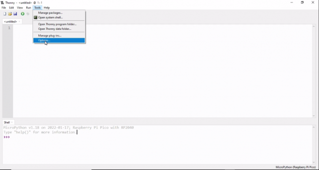
If the Thonny IDE is not in the Raspberry Pi Pico mode for that simply click on the tools, in the tools menu click on the options.
On the options windows, click on the interpreter tab, in the interpreter list, select the MicroPython (Raspberry Pi Pico) and click on the ok button.
After clicking the ok button your Thonny ide will be shifted to Raspberry Pi Pico mode, as you can see in the image given below.
Once your Thonny IDE is shifted to Raspberry Pi Pico mode, again click on tools Menu and this time click on manage packages.
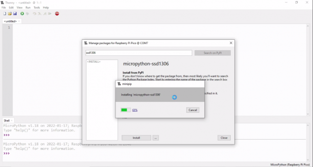
In the manage packages window, write SSD1306 in the text box and click on the search button.
Wait for the search results, it depends on the internet speed, once the searching is completed then click on the first micropython-ssd1306.
Then click on the install button, and wait for the installation process to complete.
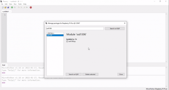
As you can see our ssd1306 library is installed successfully.
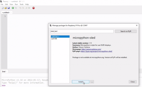
Now we have to install another library which is the micropython-oled, you might be thinking why am I installing another library? Well if you are not interested in the text size then you don’t have to install this library, you can use the SSD1306 library for printing the text and for displaying the values; but if you want to increase the fonts size then you will need this second library which I am about to install.
This time type oled_text in the text box and press the search button, and wait for the search results, it depends on the network speed.
Click on first link micropython-oled
Click on the install button and wait for installation process to complete.
As you can see our both the libraries ssd1306 and oled are installed successfully in the Raspberry Pi Pico board.
Raspberry Pi Pico SSD1306 Oled Programming:
|
1 2 3 4 5 6 7 8 9 10 11 12 13 14 15 16 |
from machine import Pin, I2C from ssd1306 import SSD1306_I2C from oled import Write, GFX, SSD1306_I2C from oled.fonts import ubuntu_mono_15, ubuntu_mono_20 import utime WIDTH =128 HEIGHT= 64 i2c=I2C(0,scl=Pin(17),sda=Pin(16),freq=200000) oled = SSD1306_I2C(WIDTH,HEIGHT,i2c) write15 = Write(oled, ubuntu_mono_15) write20 = Write(oled, ubuntu_mono_20) write20.text("OLED", 0, 0) write15.text("Display", 0, 20) oled.text("ElectroniClinic", 0, 40) oled.show() |
The purpose of this code is to print Oled, Display, and ElectroniClinic. The fonts size will be different.
|
1 2 3 |
write20.text("OLED", 0, 0) write15.text("Display", 0, 20) |
These two lines of codes uses the Oled library and
|
1 |
oled.text("ElectroniClinic", 0, 40) |
This line of code uses the SSD1306 library. I am going to run this code and you will get the idea.
This is how easily you can print text on the SSD1306 Oled display module; it depends on your requirement whether you want to use the Oled library or the SSD1306 library. Now, let’s move on to example6.
Raspberry Pi Pico Analog Sensor:
In this 6th example, I am going to use this Potentiometer as the Analog sensor with the Raspberry Pi Pico Board. You know we have two types of sensors, Digital and Analog. Digital sensor I already explained with the help of a push button. Now, to explain how to read an analog sensor, this time I will use this Potentiometer with one of the Analog pins of the Raspberry Pi Pico. So, what I am going to do next is, I will read this Potentiometer and then I will display its value on the Oled display module. So, let’s go ahead and take a look at the circuit diagram.
Analog Sensor Interfacing with Raspberry Pi Pico:
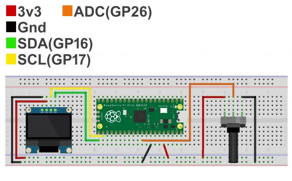
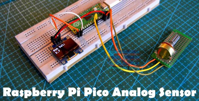
The SSD1306 Oled display module connections with the Raspberry Pi Pico remains exactly the same. Left leg of the potentiometer is connected with 3.3v, middle leg is connected with the Raspberry Pi Pico GP26 pin, and the rightmost leg is connected with the GND of the Pico board. Now let’s take a look at the programming.
Raspberry Pi Pico Analog Sensor Programming:
|
1 2 3 4 5 6 7 8 9 10 11 12 13 14 15 16 17 18 19 20 |
from machine import Pin, I2C from ssd1306 import SSD1306_I2C from oled import Write, GFX, SSD1306_I2C from oled.fonts import ubuntu_mono_15, ubuntu_mono_20 import utime pot_Val = machine.ADC(26) WIDTH = 128 HEIGHT = 64 i2c = I2C(0, scl=Pin(17), sda=Pin(16), freq=200000) conversion_factor = 3.3 / 65535 oled = SSD1306_I2C(WIDTH, HEIGHT, i2c) while True: reading = pot_Val.read_u16() data = reading * conversion_factor oled.fill(0) write20 = Write(oled, ubuntu_mono_20) write20.text("Pot Val: ", 0, 0) write20.text(str(round(data,1)),0,20) oled.show() |
The Oled display module code remains exactly the same and this time I added code for reading the Potentiometer. I defined a pin to which the Potentiometer is connected. I named the GP26 pin as pot_Val.
|
1 2 3 |
reading = pot_Val.read_u16() data = reading * conversion_factor |
These two lines of codes read the potentiometer and applies the conversion_factor. These other lines of code simply print the value on the SSD1306 Oled display module. Now, let’s run this code.
As you can see, by rotating the knob of the potentiometer, I am able to change the value. Now you can modify this code to control the LED brightness, you can control the speed of a DC motor, and so on. Now, let’s move on to Example7.
Raspberry Pi Pico Ultrasonic Sensor:
In the 7th example, I am going to use the most popular HC-SR04 Ultrasonic Sensor with the Raspberry Pi Pico. You know ultrasonic sensor is one of the most commonly used sensors and is usually used for obstacle detection in robotics, it is also used for monitoring the water level, and so on. For now, I will make a simple distance meter and you will be able to see the measured distance on the SSD1306 Oled display module. So, let’s go ahead and take a look at the circuit diagram.
Ultrasonic Sensor Interfacing with Raspberry Pi Pico:
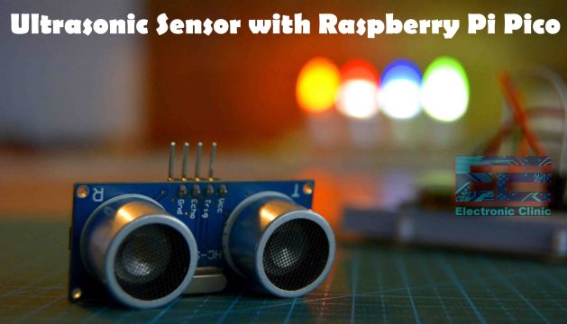
The SSD1306 Oled display module connections with the Raspberry Pi Pico remains exactly the same. The VCC pin is connected with the VBus which is Pin40 of the Raspberry Pi Pico. Trigger pin is connected with GP3, Echo pin connected with GP2, and the GND pin of the ultrasonic sensor is connected with the GND pin of the Raspberry Pi Pico board.
Ultrasonic Sensor Raspberry Pi Pico Programming:
|
1 2 3 4 5 6 7 8 9 10 11 12 13 14 15 16 17 18 19 20 21 22 23 24 25 26 27 28 29 30 31 32 33 34 35 36 37 |
from machine import Pin, I2C from ssd1306 import SSD1306_I2C from oled import Write, GFX, SSD1306_I2C from oled.fonts import ubuntu_mono_15, ubuntu_mono_20 import utime trigger = Pin(3, Pin.OUT) echo = Pin(2, Pin.IN) def distance(): timepassed=0 trigger.low() utime.sleep_us(2) trigger.high() utime.sleep_us(5) trigger.low() while echo.value() == 0: signaloff = utime.ticks_us() while echo.value() == 1: signalon = utime.ticks_us() timepassed = signalon - signaloff return timepassed WIDTH = 128 HEIGHT = 64 i2c = I2C(0, scl=Pin(17), sda=Pin(16), freq=200000) oled = SSD1306_I2C(WIDTH, HEIGHT, i2c) while True: oled.fill(0) measured_time = distance() distance_cm = (measured_time * 0.0343) / 2 oled.fill(0) write20 = Write(oled, ubuntu_mono_20) write20.text("Distance: ", 0, 0) write20.text(str(round(distance_cm,1))+" cm",0,20) oled.show() |
The SSD1306 Oled display code remains exactly the same, this time I defined the trigger and echo pins which are connected with GP3 and GP2. I defined the trigger pin as the output and the echo pin as the input.
The actual code is placed inside the distance() function which measure the time duration of the signal as it travels from the transmitter to the receiver. Finally, the measured time is converted into centimeters and then divided by 2 to get the actual distance. While these other lines of code simply display the text and measured distance on the Oled display module. Now, let’s go ahead and run this code.
I just built myself a distance meter, now I can use this for obstacle detection, for controlling an electronic Door lock, for measuring the water level inside a tank, for controlling lights, and so on. Now, let’s move on to example8.
Raspberry Pi Pico Temperature Sensor:
In this 8th example, I am going to explain how to use the Raspberry Pi Pico Onboard temperature sensor and display its value on the SSD1306 Oled display module. I going to use this temperature sensor for monitoring the ambient temperature. I don’t know if this sensor is going to give me the exact value as its directly mounted on the Pico board as it may sense some heat from the board.
This onboard temperature sensor can be quite useful in situations when used in high-temperature areas, so this sensor can monitor the Pico board temperature and when the temperature exceeds a predefined value a Fan or other cooling system is automatically turned ON. So, let’s go ahead and take a look at the circuit diagram.
Raspberry Pi Pico Temperature Sensor Circuit Diagram:
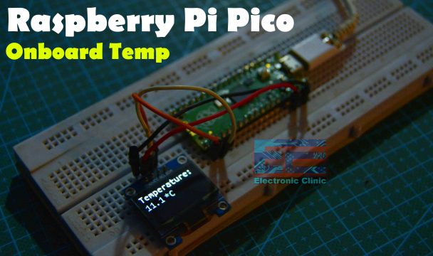
For this project, you only need to interface the SSD1306 Oled display module with the Raspberry Pi Pico. The connections I have already explained in example5.
Now, you might be thinking to which pin this onboard temperature sensor is connected? This onboard temperature sensor is connected to one of the ADCs or Analog-to-Digital Converters. The temperature sensor does not have a physical pin in the board but is accessed as ADC4. This onboard temperature sensor works by delivering a voltage to the ADC4 pin that is proportional to the temperature. If you check the Raspberry Pi Pico datasheet you will find that a temperature of 27 degrees Celsius delivers a voltage of 0.706 volts.
In the RP2040 Pico Board, the ADC pins support 12-bits, which means that the value can go from 0 to 4095. But the MicroPython code can scale the ADC values to a 16-bit range. So we effectively get the range from 0 to 65535. The microcontroller works at 3.3 V, which means that an ADC pin will return a value of 65535 when 3.3 V is applied to it or 0 when there is no voltage. We can obtain all the in-between values when the voltage applied to the pin is between 0 and 3.3 V. Let’s take a look at the code and you will get the idea.
Raspberry Pi Pico Temperature Sensor Programming:
|
1 2 3 4 5 6 7 8 9 10 11 12 13 14 15 16 17 18 19 20 21 |
from machine import Pin, I2C from ssd1306 import SSD1306_I2C from oled import Write, GFX, SSD1306_I2C from oled.fonts import ubuntu_mono_15, ubuntu_mono_20 import utime TempSensor = machine.ADC(4) WIDTH = 128 HEIGHT = 64 i2c = I2C(0, scl=Pin(17), sda=Pin(16), freq=200000) conversion_factor = 3.3 / 65535 oled = SSD1306_I2C(WIDTH, HEIGHT, i2c) while True: data = TempSensor.read_u16() * conversion_factor temperature = 27-(data-0.706)/0.001721 oled.fill(0) write20 = Write(oled, ubuntu_mono_20) write20.text("Temperature: ", 0, 0) write20.text(str(round(temperature,1)),0,20) write20.text("*C",44,20) oled.show() |
Now, you should be able to understand why am I using ADC4 and why am I dividing 3.3 by 65535. As I explained earlier, if you check the Raspberry Pi Pico datasheet you will find that a temperature of 27 degrees Celsius delivers a voltage of 0.706 volts, so that’s why you can see these numbers and then this value is used to convert the temperature reading into Celsius. So, that’s all about the code and now let’s run this code.
Now, let’s move on to example9.
Raspberry Pi Pico LDR Sensor:
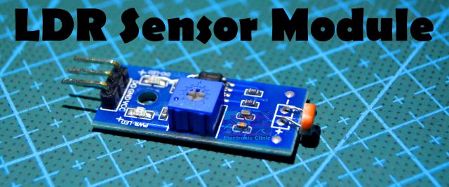
In the 9Th example, I will show you how to make the day and night detection system. This is really an important example as I will be explaining how to use an LDR sensor and a relay module for controlling a 110/220Vac Light Bulb. This LDR sensor is designed in a way that it only gives 1 or 0 as the output signal which makes it really easy to use. The light intensity level can be adjusted using this blue color potentiometer. Now, let’s go ahead and take a look at the circuit diagram.
Raspberry Pi Pico Day and Night Detection Circuit:
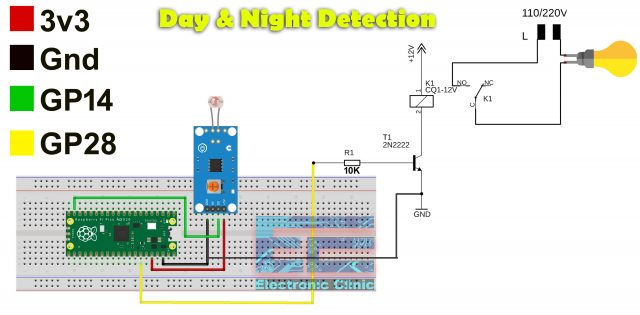
The VCC and GND pins of the LDR module are connected with 3.3Volts and GND pins of the Raspberry Pi Pico while the D0 pin of the LDR module is connected with the GP14. This LDR module is slightly different from the one I will be using. This LDR module also gives analog output. While the one I am using gives only digital output.
The one channel relay module is controlled using the GP28 pin of the Raspberry Pi Pico. You can follow these connections if you want to make your own Relay module or you can use a readymade relay module. The 2n2222 NPN transistor and a10k ohm resistor makes the driver. I have a very detailed video on how to design your own driver circuit for different types of relays. I will add a link in the description.
Anyway, the Neutral wire from the 110/220Vac is directly connected with the light and the live wire from the supply is connected with the other contact of the light through this relay. So, that’s all about the connections.
Raspberry Pi Pico Day and Night Detection Code:
|
1 2 3 4 5 6 7 8 9 10 11 12 13 |
from machine import Pin import time relay = Pin(28, Pin.OUT) ldr = Pin(14, Pin.IN, Pin.PULL_DOWN) while True: if ldr.value(): relay.value(1) time.sleep(0.5) else: relay.value(0) time.sleep(0.5) |
I defined two pins and I am going to call these as relay and ldr. As relay is an output device so that’s why I set it as output and as you know LDR sensor is an input device so that’s why I set it as input. Finally, we use an if condition to check if the output on the LDR sensor module is high or Low. So, if the Pico board detects a high signal then the Relay is turned ON, else the relay is turned OFF. Now, let’s go ahead and run this code.
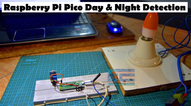
When there is light falling on the LDR sensor then the light remains OFF.
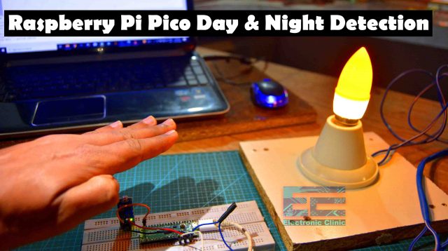
When the light on the LDR sensor falls below a preset value then the light turns ON. Using these few electronic components you can make yourself a fully automatic street lights control system or Lawn lights control system, etc. Now, let’s move on to example10.
Raspberry Pi Pico PIR Sensor:
In example10, I will show you how to use a PIR sensor and a 5V buzzer with the Raspberry Pi Pico. We will be making a small security system.
The PIR Sensor triggers the Pico Board each time motion is detected and then the Raspberry Pi Pico board turns on the Buzzer. Let’s go ahead and take a look at the circuit diagram.
Raspberry Pi Pico PIR Sensor Circuit Diagram:
The PIR Sensor Red and Black wires are connected with the Raspberry Pi Pico board 3.3V and GND pins. While the signal wire of the PIR sensor is connected with the GP14 of the Pico board. This is a 5V buzzer and it can’t be directly controlled using the Pico board; so, that’s why I am using this driver circuit to turn ON and OFF this buzzer. The base of the transistor is connected with GP28 pin of the Raspberry Pi Pico Board. So, that’s all about the connections.
Raspberry Pi Pico PIR Sensor Programming:
|
1 2 3 4 5 6 7 8 9 10 11 12 13 14 |
from machine import Pin import time buzzer = Pin(28, Pin.OUT) PirSensor = Pin(14, Pin.IN, Pin.PULL_DOWN) while True: if PirSensor.value(): buzzer.value(1) time.sleep(3) buzzer.value(0) time.sleep(5) else: buzzer.value(0) |
I defined buzzer as the output and PIR Sensor as the Input. Buzzer is connected to GP28 and PIR Sensor is connected to GP14. I am going to call these pins as the buzzer and PirSensor.
Inside the while loop, we check if the PIR sensor has detected any motion and then accordingly turn ON and turn OFF the buzzer. So, that’s all about the code.
I uploaded the code and it was working perfectly. For the practical demonstration watch video given below.
Watch Video Tutorial:
















Thanks a lot. A selection of the basic and most important codes for beginners. I am a beginner and I loved it.