Arduino and Lora based Automation Project with Feedback message, Lora SX1278
LoRa Wireless Range testing
Last Updated on September 21, 2024 by Engr. Shahzada Fahad
Table of Contents
Arduino and Lora based Automation Project:
Arduino and Lora based Automation Project with Feedback message-In this article, you will learn how to make a completely functional Automation system included with a feedback feature using a pair of Arduino boards, Lora SX1278 transceiver modules, 4-channels relay module, and some electrical loads. I will also share with you the maximum distance and how quickly and accurately it sends the feedback message.
I have already made several videos and have written many articles on SX1278 Lora transceiver modules, however, today’s article is of a somewhat different level, because the project which I am going to design today, will prove useful for you. Why am I saying so? You will get its answer during the practical demonstration.
As I have just said, I have already written many articles on Lora transceiver modules. In my very first article, I explained the pinout, technical specifications, and how to use Lora SX1278 with Arduino. So, during that project, I sent the “hello world” message wirelessly. You are well aware that for the beginners “hello world” project is an ideal project. This was basically a getting started tutorial.
After this, I explained in detail how you can conduct two-way communication over a long distance. For demonstration, I used a push button on one side, whereas on the other side I used a potentiometer as an analog sensor. If you are interested in controlling and monitoring both at the same time, then you must surely watch this video.
Anyways, after this, I implemented a Lora Network, because, in most of the cases, only two Lora modules are not enough. To cover more locations, I created a LoraWAN network based on 3 nodes. In this network, every node had a specific address. So, if you want to monitor multiple sensors from multiple locations, then this video must be worth watching for you guys.
Anyhow, I then designed a Lora Gateway and for this purpose, I used the Lora SX1278 module with ESP8266 Wi-Fi module. This is quite an interesting project because first, you bring the sensor data from a remote location, where no internet facility is available, to the node where the internet is available. And then you send that sensor data to an IoT platform with the help of a gateway. By doing so, you can monitor any sensor from any part of the world, provided you have an internet connection.
Apart from this, there are other projects as well, however, the projects which I have just mentioned, are undoubtedly very important projects, because you can design any project by modifying these projects. Let’s now move on to our todays’ project.
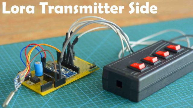
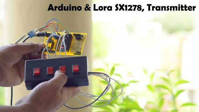
You can see 4 buttons on the transmitter side Arduino. Using these very 4 buttons, I am going to control certain loads on the receiver side. For demonstration purposes, I have put 4 bulbs on the receiver’s side, which are connected to 4 relays. Besides lights, you can use any other 110/220Vac loads or use any other DC type loads.
If you want to use 110/220Vac supply, you must not forget to use protective gloves, because 110/220Vac can prove fatal. So, as far as possible you must ensure the presence of a friend or any companion while carrying on work on such projects. When the AC supply is ON, do not touch the relay module.
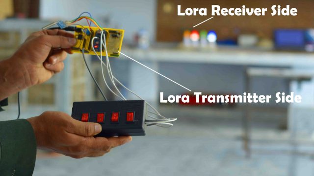
I am using the same SX1278 Lora Transceiver modules on the receiver as well as the transmitter side. Anyways, I turned ON the Receiver side using a 12V adaptor.
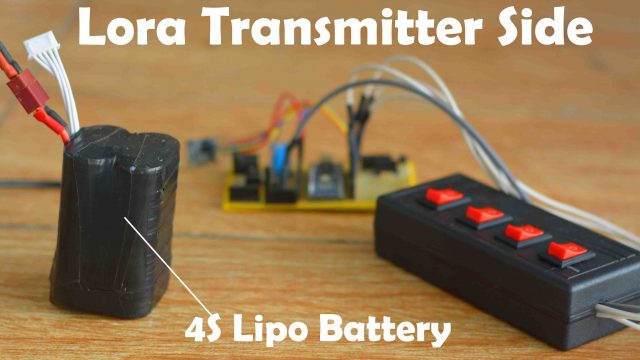
I am powering up the transmitter side through a 4S lipo battery pack. You may also use a 3S battery pack or any other type of battery or a DC adopter for this purpose. If you also want to make such a 4S Lipo battery pack, then read my article on how to make 3S and 4S lipo battery packs. Anyway, this is my portable Arduino and Lora-based remote controller, which is still passing through the testing phases. When everything gets final, I will design a small PCB and an enclosure for it. Anyways, let us start testing.
I can randomly turn ON or turn OFF any light and it is working quite superbly. This small delay occurs because I have used timers on the transmitter and receiver sides. You can increase or decrease the timer value if you want. During the line-of-sight testing there tends to be no issues. I have checked this system so many times and it is working perfectly.
However, one gets frustrated after finding that no electrical loads are visible. I am turning buttons ON and OFF, however, I cannot determine whether the loads are being controlled on the receiver’s side or not, because I cannot see loads as yet.
Perhaps, loads are being controlled, however, I am confused because still I cannot see the loads. In such a situation, we might have problems, as it is possible that Arduino might have turned OFF and you keep thinking that the signals which you are sending, are being successfully implemented, while in reality, nothing might be happening. We can solve this issue if the receiver side sends us a feedback message. And this is what I am going to do next.
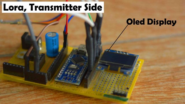
I have modified the code and you can see I have also added a display on the transmitter side. I will display the status of electrical loads on this display. So let us power up the transmitter side and see how this system works.
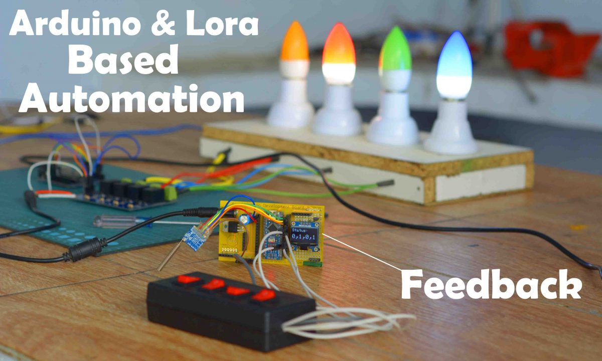
Now, Arduino and Lora-based automation systems present quite a practical look. Whenever I turn ON/OFF any button on the transmitter side, the receiver side sends me feedback on whether that load has turned ON or not.
Now even if I do not see electrical appliances or loads, there is no problem, because I keep on receiving feedback from the receiver’s side. Now, if there is some issue on the receiver side, I’ll not receive any kind of feedback. Or if I get out of the range, even then I’ll receive no feedback.
Anyways, I have been testing this project for the last two days and it is working exceptionally well.
If you are thinking about its real implementation, do not forget to use the watchdog timer on the receiver side. Because with the help of a watchdog timer, you can restart the receiver side Arduino automatically, if it hangs due to any particular reason.
Tested Range:
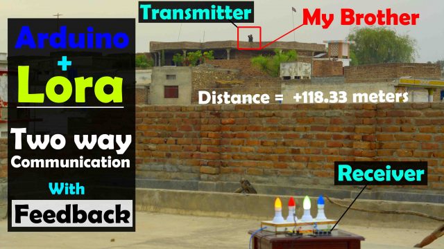
You can see my brother is standing on the roof of my maternal uncle’s house. He has the transmitter and as you can see he is controlling these light bulbs from there. The distance between the transmitter and receiver is 118 meters. Over such a long-distance still, we were able to control the bulbs. You can also watch this in the video given at the end of this article. The maximum communication distance may be more, even more than 200 meters. I will test the maximum communication distance in some open fields, as I am planning to make a transmitter for one of my upcoming RC Airplane projects.
I am sure by now you might have got an idea of how does this system works. So, without any further delay, let’s get started!!!
Amazon Links:
Arduino Nano USB-C Type (Recommended)
SSD1306 128×64 Oled i2c display Module
*Disclosure: These are affiliate links. As an Amazon Associate I earn from qualifying purchases.
SX1278 Lora:
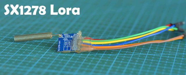
Lora 1278 long-distance wireless transceiver module integrates Semtech RF transceiver chip SX1278, which adopts LoRa TM Spread Spectrum modulation frequency hopping technique. The features of long-distance and high sensitivity (-139dBm) make this module perform better than FSK and GFSK modules. Multi-signal won’t affect each other even in a crowd frequency environment; it comes with strong anti-interference performance. This module is 100mW and ultra-small size, widely used in AMR, remote industrial control filed.
Features:
- Frequency Range: 868 / 915 MHz
- Sensitivity up to -139dBm @Lora
- Maximum output power: 20 dBm
- 13mA@receiver mode
- Sleep current <200 nA
- Data transfer rate: @FSK,1.2-300 Kbps
- @Lora TM, 0.018-37.5 Kbps
- Lora TM, FSK, GFSK & OOK Modulation mode
- Built-in ESD Protection
- 127 dB Dynamic Range RSSI
- Packet engine up to 256 bytes with FIFO and CRC
- Hopping frequency
- Built-in temperature sensor and low battery indicator
- Excellent blocking immunity
- Operating Temperature Range:-40 ~ + 85 °C
Applications:
- Remote control
- Remote meter reading
- Home security alarm and remote keyless entry
- Industrial control
- Home automation remote sensing
- Individual data records
- Toys control
- Sensor network
- Tire pressure monitoring
- Health monitoring
- Wireless PC peripherals
- Tag reading and writing
Arduino Lora Automation Project, Circuit Diagram:
Lora Transmitter Circuit Diagram:
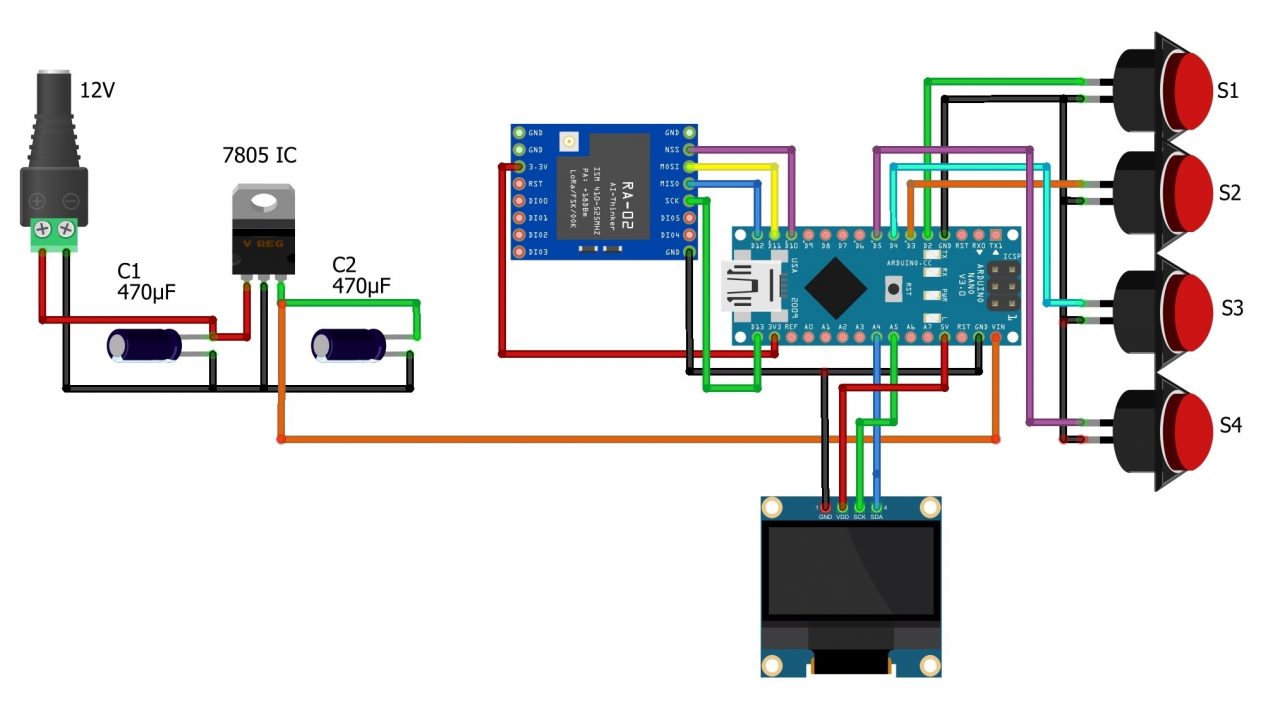
The VCC of the LoRa module is connected with the 3.3V of the Arduino. The MISO Pin of the LoRa module is connected with the Arduino’s pin 12. The MOSI pin is connected with the Arduino’s pin 11. The SCLK pin of the LoRa module is connected with the Arduino’s pin 13. The NSS pin is connected with the Arduino’s pin 10 and the ground pin of the LoRa module is connected with the Arduino’s GND.
4 switches are connected with the Arduino pins 2, 3, 4, and 5.
SSD1306 Oled display module SCL and SDA pins are connected with the Arduino’s A5 and A4 pins.
On the left side is the regulated 5V power supply which accepts a wide range of input DC voltages between 7 and 28volts.
Lora Receiver Circuit Diagram:

On the receiver side, a 4-channel relay module is connected with the Arduino pins 2, 3, 4, and 5. While the connections of the SX1278 Lora module remain exactly the same. Now, let’s take a look at the Transmitter and Receiver side programming.
Arduino Lora Automation Project, Programming:
This project is based on two programs. Download the following libraries.
Lora Transmitter programming:
|
1 2 3 4 5 6 7 8 9 10 11 12 13 14 15 16 17 18 19 20 21 22 23 24 25 26 27 28 29 30 31 32 33 34 35 36 37 38 39 40 41 42 43 44 45 46 47 48 49 50 51 52 53 54 55 56 57 58 59 60 61 62 63 64 65 66 67 68 69 70 71 72 73 74 75 76 77 78 79 80 81 82 83 84 85 86 87 88 89 90 91 92 93 94 95 96 97 98 99 100 101 102 103 104 105 106 107 108 109 110 111 112 113 114 115 116 117 118 119 120 121 122 123 124 125 126 127 128 129 130 131 132 133 134 135 136 137 138 139 140 141 142 143 144 145 146 147 148 149 150 151 152 153 154 155 156 157 158 159 160 161 162 163 164 165 166 167 168 169 170 171 172 173 174 175 176 177 178 179 180 181 182 183 |
/* Transmitter, nano */ #include <SPI.h> // include libraries #include <LoRa.h> #include <Adafruit_GFX.h> #include <Adafruit_SSD1306.h> byte msgCount = 0; // count of outgoing messages byte localAddress = 0xBB; // address of this device byte destination = 0xFF; // destination to send to long lastSendTime = 0; // last send time int interval = 50; // interval between sends // 4 buttons or switches int sw1 = 2; int sw2 = 4; int sw3 = 6; int sw4 = 8; // Stores the switches or buttons status in the form of 0 or 1 // And then these status values are used to control the loads // on the Receiver side. int Sensor1 = 0; int Sensor2 = 0; int Sensor3 = 0; int Sensor4 = 0; //The receiver side loads status feedback values are stored in the following variables int load1 = 0; int load2 = 0; int load3 = 0; int load4 = 0; boolean bflag = false; String outgoing; // outgoing message // For Oled display #define SCREEN_WIDTH 128 // OLED display width, in pixels #define SCREEN_HEIGHT 64 // OLED display height, in pixels // Declaration for an SSD1306 display connected to I2C (SDA, SCL pins) #define OLED_RESET -1 // Reset pin # (or -1 if sharing Arduino reset pin) Adafruit_SSD1306 display(SCREEN_WIDTH, SCREEN_HEIGHT, &Wire, OLED_RESET); String Mymessage = ""; void setup() { Serial.begin(9600); // initialize serial display.begin(SSD1306_SWITCHCAPVCC, 0x3C); display.clearDisplay(); display.setTextColor(WHITE); pinMode(sw1, INPUT_PULLUP); pinMode(sw2, INPUT_PULLUP); pinMode(sw3, INPUT_PULLUP); pinMode(sw4, INPUT_PULLUP); Serial.println("LoRa Duplex"); if (!LoRa.begin(433E6)) { // initialize ratio at 915 MHz Serial.println("LoRa init failed. Check your connections."); while (true); // if failed, do nothing } Serial.println("LoRa init succeeded."); } void loop() { if (millis() - lastSendTime > interval) { Sensor1 = digitalRead(sw1); Sensor2 = digitalRead(sw2); Sensor3 = digitalRead(sw3); Sensor4 = digitalRead(sw4); Mymessage = Mymessage + !Sensor1 +"," + !Sensor2 + "," + !Sensor3 +"," + !Sensor4; sendMessage(Mymessage); delay(10); Mymessage = ""; //Serial.println("Sending " + message); lastSendTime = millis(); // timestamp the message interval = random(50) + 100; } // parse for a packet, and call onReceive with the result: onReceive(LoRa.parsePacket()); } void sendMessage(String outgoing) { LoRa.beginPacket(); // start packet LoRa.write(destination); // add destination address LoRa.write(localAddress); // add sender address LoRa.write(msgCount); // add message ID LoRa.write(outgoing.length()); // add payload length LoRa.print(outgoing); // add payload LoRa.endPacket(); // finish packet and send it msgCount++; // increment message ID } void onReceive(int packetSize) { if (packetSize == 0) return; // if there's no packet, return // read packet header bytes: int recipient = LoRa.read(); // recipient address byte sender = LoRa.read(); // sender address byte incomingMsgId = LoRa.read(); // incoming msg ID byte incomingLength = LoRa.read(); // incoming msg length String incoming = ""; while (LoRa.available()) { incoming += (char)LoRa.read(); } if (incomingLength != incoming.length()) { // check length for error //Serial.println("error: message length does not match length"); ; return; // skip rest of function } // if the recipient isn't this device or broadcast, if (recipient != localAddress && recipient != 0xFF) { // Serial.println("This message is not for me."); ; return; // skip rest of function } // if message is for this device, or broadcast, print details: //Serial.println("Received from: 0x" + String(sender, HEX)); //Serial.println("Sent to: 0x" + String(recipient, HEX)); //Serial.println("Message ID: " + String(incomingMsgId)); // Serial.println("Message length: " + String(incomingLength)); // Serial.println("Message: " + incoming); // Serial.println("RSSI: " + String(LoRa.packetRssi())); // Serial.println("Snr: " + String(LoRa.packetSnr())); // Serial.println(); String q = getValue(incoming, ',', 0); String r = getValue(incoming, ',', 1); String s = getValue(incoming, ',', 2); String t = getValue(incoming, ',', 3); load1 = q.toInt(); load2 = r.toInt(); load3 = s.toInt(); load4 = t.toInt(); String DisplayData = ""; DisplayData = DisplayData + load1 + "," + load2 + "," + load3 + "," + load4 ; //new code end //clear display display.clearDisplay(); display.setTextSize(2); display.setCursor(0,0); display.print("Status:"); display.setTextSize(3); display.setCursor(0, 28); display.print(DisplayData); display.display(); } String getValue(String data, char separator, int index) { int found = 0; int strIndex[] = { 0, -1 }; int maxIndex = data.length() - 1; for (int i = 0; i <= maxIndex && found <= index; i++) { if (data.charAt(i) == separator || i == maxIndex) { found++; strIndex[0] = strIndex[1] + 1; strIndex[1] = (i == maxIndex) ? i+1 : i; } } return found > index ? data.substring(strIndex[0], strIndex[1]) : ""; } |
Lora Transmitter Code Explanation:
|
1 2 3 |
#include <Adafruit_GFX.h> #include <Adafruit_SSD1306.h> |
I added the Adafruit_GFX and Adafruit_SSD1306 libraries for the Oled display module. You can download these libraries from my article.
|
1 2 3 4 5 6 7 8 9 |
byte msgCount = 0; // count of outgoing messages byte localAddress = 0xBB; // address of this device byte destination = 0xFF; // destination to send to long lastSendTime = 0; // last send time int interval = 50; // interval between sends |
Next, I defined the localAddress, destination, and these variables for the timer.
|
1 2 3 4 5 6 7 8 9 |
// 4 buttons or switches int sw1 = 2; int sw2 = 4; int sw3 = 6; int sw4 = 8; |
Next, I defined 4 switches.
|
1 2 3 4 5 6 7 |
int Sensor1 = 0; int Sensor2 = 0; int Sensor3 = 0; int Sensor4 = 0; |
Next, I defined these 4 variables for storing the status of all the 4 switches in the form of 0 and 1. We use these status values to control relays on the receiver side.
|
1 2 3 4 5 6 7 |
int load1 = 0; int load2 = 0; int load3 = 0; int load4 = 0; |
Next, I defined these 4 variables to store the status feedback values of the 4 loads received from the receiver side. Now, let’s go to the loop function.
|
1 2 3 4 5 6 7 8 9 10 11 12 13 14 15 16 17 18 19 20 21 22 23 24 25 26 27 28 29 30 31 32 33 34 35 36 37 38 39 40 41 42 |
void loop() { if (millis() - lastSendTime > interval) { Sensor1 = digitalRead(sw1); Sensor2 = digitalRead(sw2); Sensor3 = digitalRead(sw3); Sensor4 = digitalRead(sw4); Mymessage = Mymessage + !Sensor1 +"," + !Sensor2 + "," + !Sensor3 +"," + !Sensor4; sendMessage(Mymessage); delay(10); Mymessage = ""; //Serial.println("Sending " + message); lastSendTime = millis(); // timestamp the message interval = random(50) + 100; } // parse for a packet, and call onReceive with the result: onReceive(LoRa.parsePacket()); } |
First, we read the status of the switches, then we make a complete message and send it to the receiver side. Arduino checks and sends the control commands after every few milliseconds. If you want you can change the interval. After sending the message then the Arduino checks if any data is received from the receiver side.
|
1 2 3 4 5 6 7 8 9 10 11 12 13 14 15 16 17 18 19 20 21 22 23 24 25 26 27 28 29 30 31 32 33 34 35 36 37 38 39 40 41 42 43 44 45 46 47 48 49 50 51 52 53 54 55 56 57 58 59 60 61 62 63 64 65 66 67 68 69 70 71 72 73 74 75 76 77 78 79 80 81 82 83 84 85 86 87 88 89 90 91 92 93 94 95 96 97 98 99 100 101 102 103 104 105 106 107 108 109 110 111 112 113 114 115 116 117 118 119 120 121 |
void onReceive(int packetSize) { if (packetSize == 0) return; // if there's no packet, return // read packet header bytes: int recipient = LoRa.read(); // recipient address byte sender = LoRa.read(); // sender address byte incomingMsgId = LoRa.read(); // incoming msg ID byte incomingLength = LoRa.read(); // incoming msg length String incoming = ""; while (LoRa.available()) { incoming += (char)LoRa.read(); } if (incomingLength != incoming.length()) { // check length for error //Serial.println("error: message length does not match length"); ; return; // skip rest of function } // if the recipient isn't this device or broadcast, if (recipient != localAddress && recipient != 0xFF) { // Serial.println("This message is not for me."); ; return; // skip rest of function } String q = getValue(incoming, ',', 0); String r = getValue(incoming, ',', 1); String s = getValue(incoming, ',', 2); String t = getValue(incoming, ',', 3); load1 = q.toInt(); load2 = r.toInt(); load3 = s.toInt(); load4 = t.toInt(); String DisplayData = ""; DisplayData = DisplayData + load1 + "," + load2 + "," + load3 + "," + load4 ; //new code end //clear display display.clearDisplay(); display.setTextSize(2); display.setCursor(0,0); display.print("Status:"); display.setTextSize(3); display.setCursor(0, 28); display.print(DisplayData); display.display(); } |
The data which is received from the receiver side is the feedback message, this feedback message consists of the relays status in the form 0 and 1. So, the incoming message is split and the feedback status values are stored in their respective variables, where its values are displayed on the Oled display module.
|
1 2 3 4 5 6 7 8 9 10 11 12 13 14 15 16 17 18 19 20 21 22 23 24 25 26 27 28 29 30 |
String getValue(String data, char separator, int index) { int found = 0; int strIndex[] = { 0, -1 }; int maxIndex = data.length() - 1; for (int i = 0; i <= maxIndex && found <= index; i++) { if (data.charAt(i) == separator || i == maxIndex) { found++; strIndex[0] = strIndex[1] + 1; strIndex[1] = (i == maxIndex) ? i+1 : i; } } return found > index ? data.substring(strIndex[0], strIndex[1]) : ""; } |
The getValue() function is used to split a string message using a delimiter. In my case, I am using Comma as the delimiter, if you want you can use any other character as the delimiter. So, that’s all about the transmitter side programming, and now let’s take a look at the receiver side programming.
Lora Receiver Programming:
|
1 2 3 4 5 6 7 8 9 10 11 12 13 14 15 16 17 18 19 20 21 22 23 24 25 26 27 28 29 30 31 32 33 34 35 36 37 38 39 40 41 42 43 44 45 46 47 48 49 50 51 52 53 54 55 56 57 58 59 60 61 62 63 64 65 66 67 68 69 70 71 72 73 74 75 76 77 78 79 80 81 82 83 84 85 86 87 88 89 90 91 92 93 94 95 96 97 98 99 100 101 102 103 104 105 106 107 108 109 110 111 112 113 114 115 116 117 118 119 120 121 122 123 124 125 126 127 128 129 130 131 132 133 134 135 136 137 138 139 140 141 142 143 144 145 146 147 148 149 150 151 152 153 154 155 156 157 158 159 160 161 162 163 164 165 166 167 168 169 170 171 172 173 174 175 176 177 178 179 180 181 182 183 184 185 186 187 188 189 190 191 192 193 194 195 196 197 198 199 200 201 202 203 204 205 206 207 208 209 210 211 212 213 214 215 216 217 218 219 220 221 222 223 224 225 226 227 228 229 230 231 |
/* Receiver, Nano */ #include <SPI.h> // include libraries #include <LoRa.h> byte msgCount = 0; // count of outgoing messages byte localAddress = 0xFF; // address of this device byte destination = 0xBB; // destination to send to long lastSendTime = 0; // last send time int interval = 50; // interval between sends // flags to stop the unneccesary repition boolean flag1 = false; boolean flag2 = false; boolean flag3 = false; boolean flag4 = false; int RLY1=2; int RLY2=3; int RLY3=4; int RLY4=5; // these variables are used to store the control commands received from the Transmitter int Sensor1 = 0; int Sensor2 = 0; int Sensor3 = 0; int Sensor4 = 0; // stores the relays status int relay1Status; int relay2Status; int relay3Status; int relay4Status; String outgoing; // outgoing message String statusmessage = ""; void setup() { Serial.begin(9600); // initialize serial pinMode(RLY1,OUTPUT); pinMode(RLY2,OUTPUT); pinMode(RLY3,OUTPUT); pinMode(RLY4,OUTPUT); Serial.println("LoRa Duplex"); if (!LoRa.begin(433E6)) { // initialize ratio at 915 MHz Serial.println("LoRa init failed. Check your connections."); while (true); // if failed, do nothing } Serial.println("LoRa init succeeded."); } void loop() { if (millis() - lastSendTime > interval) { relay1Status = digitalRead(RLY1); relay2Status = digitalRead(RLY2); relay3Status = digitalRead(RLY3); relay4Status = digitalRead(RLY4); statusmessage = statusmessage + relay1Status + "," + relay2Status + "," + relay3Status + "," + relay4Status; sendMessage(statusmessage); delay(10); statusmessage = ""; lastSendTime = millis(); // timestamp the message interval = random(50) + 100; // 2-3 seconds } // parse for a packet, and call onReceive with the result: onReceive(LoRa.parsePacket()); } void sendMessage(String outgoing) { LoRa.beginPacket(); // start packet LoRa.write(destination); // add destination address LoRa.write(localAddress); // add sender address LoRa.write(msgCount); // add message ID LoRa.write(outgoing.length()); // add payload length LoRa.print(outgoing); // add payload LoRa.endPacket(); // finish packet and send it msgCount++; // increment message ID } void onReceive(int packetSize) { if (packetSize == 0) return; // if there's no packet, return // read packet header bytes: int recipient = LoRa.read(); // recipient address byte sender = LoRa.read(); // sender address byte incomingMsgId = LoRa.read(); // incoming msg ID byte incomingLength = LoRa.read(); // incoming msg length String incoming = ""; while (LoRa.available()) { incoming += (char)LoRa.read(); } if (incomingLength != incoming.length()) { // check length for error // Serial.println("error: message length does not match length"); ; return; // skip rest of function } // if the recipient isn't this device or broadcast, if (recipient != localAddress && recipient != 0xFF) { //Serial.println("This message is not for me."); ; return; // skip rest of function } // if message is for this device, or broadcast, print details: // Serial.println("Received from: 0x" + String(sender, HEX)); // Serial.println("Sent to: 0x" + String(recipient, HEX)); //Serial.println("Message ID: " + String(incomingMsgId)); // Serial.println("Message length: " + String(incomingLength)); // Serial.println("Message: " + incoming); //Serial.println("RSSI: " + String(LoRa.packetRssi())); //Serial.println("Snr: " + String(LoRa.packetSnr())); // Serial.println(); String q = getValue(incoming, ',', 0); String r = getValue(incoming, ',', 1); String s = getValue(incoming, ',', 2); String t = getValue(incoming, ',', 3); Sensor1 = q.toInt(); Sensor2 = r.toInt(); Sensor3 = s.toInt(); Sensor4 = t.toInt(); if((Sensor1 == 1)&&(flag1==false)) { digitalWrite(RLY1,HIGH); relay1Status = 1; Serial.println("Relay 1 is turned on"); flag1=true; } if((Sensor1 == 0)&&(flag1 ==true)) { digitalWrite(RLY1,LOW); relay1Status = 0; Serial.println("Relay 1 is turned off"); flag1=false; } if((Sensor2 == 1)&&(flag2==false)) { digitalWrite(RLY2,HIGH); relay2Status = 0; Serial.println("Relay 2 is turned on"); flag2=true; } if((Sensor2 == 0)&&(flag2 ==true)) { digitalWrite(RLY2,LOW); relay2Status = 0; Serial.println("Relay 2 is turned off"); flag2=false; } if((Sensor3 == 1)&&(flag3==false)) { digitalWrite(RLY3,HIGH); relay3Status = 1; Serial.println("Relay 3 is turned on"); flag3=true; } if((Sensor3 == 0)&&(flag3 ==true)) { digitalWrite(RLY3,LOW); relay3Status = 0; Serial.println("Relay 3 is turned off"); flag3=false; } if((Sensor4 == 1)&&(flag4==false)) { digitalWrite(RLY4,HIGH); relay4Status = 1; Serial.println("Relay 4 is turned on"); flag4=true; } if((Sensor4 == 0)&&(flag4 ==true)) { digitalWrite(RLY4,LOW); relay4Status = 0; Serial.println("Relay 4 is turned off"); flag4=false; } incoming = ""; } String getValue(String data, char separator, int index) { int found = 0; int strIndex[] = { 0, -1 }; int maxIndex = data.length() - 1; for (int i = 0; i <= maxIndex && found <= index; i++) { if (data.charAt(i) == separator || i == maxIndex) { found++; strIndex[0] = strIndex[1] + 1; strIndex[1] = (i == maxIndex) ? i+1 : i; } } return found > index ? data.substring(strIndex[0], strIndex[1]) : ""; } |
Lora Receiver code Explanation:
|
1 2 3 4 5 6 7 8 9 10 11 12 13 14 15 16 |
#include <SPI.h> // include libraries #include <LoRa.h> byte msgCount = 0; // count of outgoing messages byte localAddress = 0xFF; // address of this device byte destination = 0xBB; // destination to send to long lastSendTime = 0; // last send time int interval = 50; // interval between sends |
On the receiver side, I am using the same libraries, addresses, and timer intervals.
|
1 2 3 4 5 6 7 |
boolean flag1 = false; boolean flag2 = false; boolean flag3 = false; boolean flag4 = false; |
This time I also defined these 4 flags, I am using these flags to stop the unnecessary repetition of code.
|
1 2 3 4 5 6 7 |
int RLY1=2; int RLY2=3; int RLY3=4; int RLY4=5; |
Next, you can see I also defined pins for the 4 relays.
|
1 2 3 4 5 6 7 |
int Sensor1 = 0; int Sensor2 = 0; int Sensor3 = 0; int Sensor4 = 0; |
Next, I defined these 4 variables for storing the control commands received from the transmitter. These control commands are used to control all the 4 relays.
|
1 2 3 4 5 6 7 |
int relay1Status; int relay2Status; int relay3Status; int relay4Status; |
Finally, I am using these 4 variables to store the status of all the 4 relays. These values are used to create the feedback message which is sent to the transmitter side. Now, let’s go to the loop function.
|
1 2 3 4 5 6 7 8 9 10 11 12 13 14 15 16 17 18 19 20 21 22 23 24 25 26 27 28 29 30 31 32 33 34 35 36 37 38 39 40 41 42 43 44 45 46 |
void loop() { if (millis() - lastSendTime > interval) { relay1Status = digitalRead(RLY1); relay2Status = digitalRead(RLY2); relay3Status = digitalRead(RLY3); relay4Status = digitalRead(RLY4); statusmessage = statusmessage + relay1Status + "," + relay2Status + "," + relay3Status + "," + relay4Status; sendMessage(statusmessage); delay(10); statusmessage = ""; lastSendTime = millis(); // timestamp the message interval = random(50) + 100; // 2-3 seconds } // parse for a packet, and call onReceive with the result: onReceive(LoRa.parsePacket()); } |
Now, this time I am reading the status of all the four relays, then we create a complete message, which is the feedback message and send it to the transmitter side.
|
1 2 3 4 5 6 7 8 9 10 11 12 13 14 15 16 17 18 19 20 21 22 23 24 25 26 27 28 29 30 31 32 33 34 35 36 37 38 39 40 41 42 43 44 45 46 47 48 49 50 51 52 53 54 55 56 57 58 59 60 61 62 63 64 65 66 67 68 69 70 71 72 73 74 75 76 77 78 79 80 81 82 83 84 85 86 87 88 89 90 91 92 93 94 95 96 97 98 99 100 101 102 103 104 105 106 107 108 109 110 111 112 113 114 115 116 117 118 119 120 121 122 123 124 125 126 127 128 129 130 131 132 133 134 135 136 137 138 139 140 141 142 143 144 145 146 147 148 149 150 151 152 153 154 155 156 157 158 159 160 161 162 163 164 165 166 167 168 169 170 171 172 173 174 175 176 177 178 179 180 181 182 183 184 185 186 187 188 189 190 191 192 193 194 195 196 197 198 199 200 201 202 203 204 205 206 207 208 209 210 211 212 213 214 215 216 217 218 219 220 221 222 223 224 225 226 227 228 229 230 231 232 233 234 235 236 237 238 239 240 241 242 243 244 245 246 247 |
void onReceive(int packetSize) { if (packetSize == 0) return; // if there's no packet, return // read packet header bytes: int recipient = LoRa.read(); // recipient address byte sender = LoRa.read(); // sender address byte incomingMsgId = LoRa.read(); // incoming msg ID byte incomingLength = LoRa.read(); // incoming msg length String incoming = ""; while (LoRa.available()) { incoming += (char)LoRa.read(); } if (incomingLength != incoming.length()) { // check length for error // Serial.println("error: message length does not match length"); ; return; // skip rest of function } // if the recipient isn't this device or broadcast, if (recipient != localAddress && recipient != 0xFF) { //Serial.println("This message is not for me."); ; return; // skip rest of function } String q = getValue(incoming, ',', 0); String r = getValue(incoming, ',', 1); String s = getValue(incoming, ',', 2); String t = getValue(incoming, ',', 3); Sensor1 = q.toInt(); Sensor2 = r.toInt(); Sensor3 = s.toInt(); Sensor4 = t.toInt(); if((Sensor1 == 1)&&(flag1==false)) { digitalWrite(RLY1,HIGH); relay1Status = 1; Serial.println("Relay 1 is turned on"); flag1=true; } if((Sensor1 == 0)&&(flag1 ==true)) { digitalWrite(RLY1,LOW); relay1Status = 0; Serial.println("Relay 1 is turned off"); flag1=false; } if((Sensor2 == 1)&&(flag2==false)) { digitalWrite(RLY2,HIGH); relay2Status = 0; Serial.println("Relay 2 is turned on"); flag2=true; } if((Sensor2 == 0)&&(flag2 ==true)) { digitalWrite(RLY2,LOW); relay2Status = 0; Serial.println("Relay 2 is turned off"); flag2=false; } if((Sensor3 == 1)&&(flag3==false)) { digitalWrite(RLY3,HIGH); relay3Status = 1; Serial.println("Relay 3 is turned on"); flag3=true; } if((Sensor3 == 0)&&(flag3 ==true)) { digitalWrite(RLY3,LOW); relay3Status = 0; Serial.println("Relay 3 is turned off"); flag3=false; } if((Sensor4 == 1)&&(flag4==false)) { digitalWrite(RLY4,HIGH); relay4Status = 1; Serial.println("Relay 4 is turned on"); flag4=true; } if((Sensor4 == 0)&&(flag4 ==true)) { digitalWrite(RLY4,LOW); relay4Status = 0; Serial.println("Relay 4 is turned off"); flag4=false; } incoming = ""; } |
Then the Arduino checks if any data is received. This time the received message consists of the control commands which are received from the Transmitter. The Arduino splits the entire message and then using the if conditions the relays are turned ON or turned OFF depending on the received values. So, that’s all about the programming.
Watch Video Tutorial:

Discover more from Electronic Clinic
Subscribe to get the latest posts sent to your email.


Great project, just one question can I use the Arduino Nano for both tx and rx?
Friend, tell me how you can use LEDs instead of a display, how to do it, tell me