IoT Doorbell Project, Wifi Doorbell, Smart doorbell without contact using ESP8266
Last Updated on September 19, 2024 by Engr. Shahzada Fahad
Table of Contents
IoT Doorbell Project Description:
IoT Doorbell Project- you can call this project with different names e.g. IoT Doorbell or Wifi Doorbell or Wireless Doorbell or Smart Doorbell etc. Keeping in mind the Covid-19 “Corona Virus” situation going on all over the world, I decided to make a Wireless smart IoT Doorbell based on the Wifi and IR sensor.
The Doorbells are among the most germ-infected objects in houses, hospitals, factories, and elderly homes. We stand behind our mission to build a better and healthier world, which is why we are making this project. This project will control and avoid further passing on COVID-19. Let’s work together to stop the spread!
This Smart wireless non-contact IoT Doorbell based on the Wifi and IR sensor is very user friendly, you can make this by yourself, if you follow this tutorial. Before, I am going to explain the circuit diagrams and programming, first, I am going to explain how this project works.
While you are away from your house let’s say 1 or 2 Kilometers, you can simply take out your cell phone, open the application and press a button on your Android or Mac cell phone, a buzzer at home will turn ON which informs the house members about your arrival and they open the door for you. This way you don’t have to wait at the door for minutes.
For others an IR sensor is also connected with the Nodemcu ESP8266 module, they simply wave their hand in front of the IR Sensor and the sound buzzer will turn ON for a few seconds. This way there is no need to physically press any button. This Smart non-contact IoT Doorbell based on the Wifi and IR Sensor is completely touch free.
In this tutorial we will cover
- IoT Doorbell Circuit Diagram Explanation
- IoT Doorbell Cell phone App designing in Blynk
- IoT Doorbell Nodemcu ESP8266 Programming
For the Beginners:
If you have never used the Nodemcu ESP8266 Wifi Module, then I highly recommend watch my previous getting started and basics video tutorials explaining how to get started with the Nodemcu ESP8266 Wifi module.
- Nodemcu esp8266 wifi Module Basics, Board installation, Library, Blynk Application, Usb uart Drive
- Power Supply Designing and making for the Nodemcu ESP8266
Without any further delay, let’s get started!!!
Amazon Product links:
*Please Note: These are affiliate links. I may make a commission if you buy the components through these links. I would appreciate your support in this way!
About the Nodemcu ESP8266 Pinout:

NodeMCU ESP8266 Wifi Module is an open-source Lua based firmware and development board specially targeted for IoT based applications. It includes firmware that runs on the ESP8266 Wi-Fi SoC from Espressif Systems, and hardware which is based on the ESP-12 module.
Nodemcu ESP8266 Specifications & Features
Microcontroller: Tensilica 32-bit RISC CPU Xtensa LX106
Operating Voltage: 3.3V
Input Voltage: 7-12V
Digital I/O Pins (DIO): 16
Analog Input Pins (ADC): 1
UARTs: 1
SPIs: 1
I2Cs: 1
Flash Memory: 4 MB
SRAM: 64 KB
Clock Speed: 80 MHz
USB-TTL based on CP2102 is included onboard, Enabling Plug n Play
PCB Antenna
Small Sized module to fit smartly inside your IoT projects
Nodemcu ESP8266 Pinout:
For practical purposes ESP8266 NodeMCU V2 and V3 boards present identical pinouts. While working on the NodeMCU based projects we are interested in the following pins.
Power pins (3.3 V).
Ground pins (GND).
Analog pins (A0).
Digital pins (D0 – D8, SD2, SD3, RX and TX – GPIO XX)
Most ESP8266 NodeMCU boards have one input voltage pin (Vin), three power pins (3.3v), four ground pins (GND), one analog pin (A0) and several digital pins (GPIO XX).
Pin Code Arduino alias
A0 A0 A0
D0 GPIO 16 16
D1 GPIO 5 5
D2 GPIO 4 4
D3 GPIO 0 0
D4 GPIO 2 2
D5 GPIO 14 14
D6 GPIO 12 12
D7 GPIO 13 13
D8 GPIO 15 15
SD2 GPIO 9 9
SD3 GPIO 10 10
RX GPIO 3 3
TX GPIO 1 1
Applications of Nodemcu
Prototyping of IoT devices
Low power battery operated applications
Network projects
Projects requiring multiple I/O interfaces with Wi-Fi and Bluetooth functionalities
Programming Nodemcu ESP8266 with Arduino IDE
The Nodemcu ESP8266 Development Board can be easily programmed using the Arduino IDE since it is easy to use. Programming Nodemcu ESP8266 with the Arduino IDE will hardly take 10-20 minutes. All you need is the latest version of the Arduino IDE, a USB cable and the Nodemcu ESP8266 board itself. You can check this Getting Started Tutorial for NodeMCU to prepare your Arduino IDE for Nodemcu ESP8266. You can also check my getting started tutorial for ESP32 Wifi + Bluetooth Module to prepare your Arduino IDE for ESP32 module.
IoT Doorbell Project Circuit Diagram:

On the left side is the 5V regulated power supply based on the LM7805 Linear voltage regulator. This regulated power supply is used to power up the NodeMCU ESP8266 Module. The external 12V power supply is connected through the input female power jack J1. Two 470uF electrolytic Capacitors are connected at the input and output sides of the voltage regulator, these are the decoupling capacitors. A 330 ohm resistor is connected in series with a 2.5V LED. This is a current limiting resistor.
A wire from the output of the voltage regulator is connected with the VIN pin of the NodeMCU ESP8266 Wifi module, while the ground of the power supply is connected with the ground pin of the NodeMCU module.
The positive pin of the Buzzer is connected with the 3.3V pin of the NodeMCU module. The ground pin of the buzzer is connected with the collector of the 2n2222 NPN Transistor. This 2n2222 NPN bipolar junction transistor is used as the driver which controls the buzzer. The base of the Transistor is connected with the D2 pin of the NodeMCU through a 10k ohm resistor.
The IR Sensor power supply pins are connected with the 3.3V and Ground pins, while the output pin of the IR Sensor is connected with the D0 pin of the NodeMCU module.
If the IR sensor detects an movement the buzzer will turn ON. If you want to control 220Vac buzzer then you can connect a 12V relay. Read my other articles on the NodeMCU module to learn how to use a relay with the NodeMCU module.
NodeMCU board with IR Sensor and Buzzer:
Download link of the Nodemcu library for Cadsoft eagle:
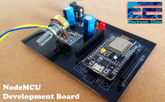
A started off by designing a PCB for the Nodemcu ESP8266 Wifi Module so that I can use it in multiple projects for testing. So, this is a kind of NodeMCU prototype development board. For the designing and making of this PCB board watch my tutorial. You can see potentiometer being soldered; in this project we will not use this potentiometer.

The purpose I didn’t soldered the Buzzer on the NodeMCU PCB board is that I am going to use this buzzer module in some other projects. If you want you can solder all the electronics on one PCB board.

Finally, I connected everything as per the circuit diagram already explained above.

Our hardware is ready, now let make the cell phone application using Blynk.
Note: this old version of the Blynk app is no more functional. For the blynk mobile App setup and Blynk.cloud dashboard setup ready my article on the New Blynk V2.0. In this article I have explained how to migrate your projects from Blynk 1.0 to the new Blynk V2.0. You can also watch the video.
IoT Doorbell Cell phone Application designing in Blynk:
I always first start with the Blynk application designing, this way I know which digital and virtual pins I have to use in the programming. Moreover this also helps me in checking my code, as I keep testing my project. Make sure you have downloaded and installed the Blynk application.
- First of all open the blynk application.
- Click on the new project and enter the project name as “IoT Doorbell”. If you want you can select any other name. Later you can also modify the name.
- Click on the choose device and select Nodemcu.
- Make sure the connection type is set to WIFI.
- Finally, click on the create button, an authentication token will be sent on your email id, which later will be used in the Nodemcu programming.
- Click anywhere on the screen and search for the button and add it. Now, click on the button, change the name or leave it as it is. Click on the output and select GP0. Select the button mode as the switch and finally you can change the font size. Your designed IoT Doorbell application should look something like this,

Isn’t it amazing, how fast and easily we can create cell phone applications. Anyhow, our application is ready, now the final step is the IoT Doorbell NodeMCU Programming.
Before, you start the programming, first of all, make sure you download all the necessary libraries.
IoT Doorbell Project Programming:
|
1 2 3 4 5 6 7 8 9 10 11 12 13 14 15 16 17 18 19 20 21 22 23 24 25 26 27 28 29 30 31 32 33 34 35 36 37 38 39 40 41 42 43 44 45 46 47 48 49 50 51 52 53 54 55 56 57 58 59 60 61 62 63 64 65 66 67 |
// IoT Doorbell Project by //https://www.electroniclinic.com/ /* Nodemcu ESP8266 & Blynk */ #include <ESP8266WiFi.h> #include <BlynkSimpleEsp8266.h> #include <SimpleTimer.h> #define BLYNK_PRINT Serial // Comment this out to disable prints and save space char auth[] = "Ay7TN0ucWH-aFJKX-h7cV07_as2omOHu"; /* WiFi credentials */ char ssid[] = "AndroidAP7DF8"; char pass[] = "jamshaid12"; SimpleTimer timer; int IRsensor = D0; // IR Sensor Connected int Buzzer = D2; void setup() { Serial.begin(115200); Blynk.begin(auth, ssid, pass); pinMode(IRsensor, INPUT_PULLUP); pinMode(D3, INPUT); pinMode(Buzzer, OUTPUT); timer.setInterval(1000L, Sensor); timer.setInterval(1000L, FromApp); } void loop() { timer.run(); // Initiates SimpleTimer Blynk.run(); } void Sensor() { while( digitalRead(IRsensor) == LOW) { digitalWrite(Buzzer, HIGH); delay(2000); // Buzzer remains ON for 2 seconds. Blynk.begin(auth, ssid, pass); // this again connects the Blynk application. } } void FromApp() { if(digitalRead(D3) == HIGH) // D3 is gp0 on the blynk app { digitalWrite(Buzzer, HIGH); } if(digitalRead(D3) == LOW) { digitalWrite(Buzzer, LOW); } } |
IoT Doorbell Code Explanation:
First of all, I started by adding the libraries, the download link is already given above.
|
1 2 3 4 5 6 7 8 9 |
#include <ESP8266WiFi.h> #include <BlynkSimpleEsp8266.h> #include <SimpleTimer.h> #define BLYNK_PRINT Serial // Comment this out to disable prints and save space char auth[] = "Ay7TN0ucWH-aFJKX-h7cV07_as2omOHu"; |
This is the authentication token which was sent via email while making the Blynk application. This authentication token will be mailed on your registered email ID.
|
1 2 3 4 5 6 7 8 9 10 11 12 13 14 15 16 17 18 19 20 21 22 23 24 25 26 27 28 29 30 31 32 33 |
/* WiFi credentials */ char ssid[] = "AndroidAP7DF8"; char pass[] = "electroniclinic"; these are the WiFi router details, the name and the password, currently I am using a hotspot. SimpleTimer timer; int IRsensor = D0; // IR Sensor Connected with D0 pin of the NodeMCU int Buzzer = D2; // the buzzer is connected with the D2 pin of the NodeMCU ESP8266 void setup() { Serial.begin(115200); Blynk.begin(auth, ssid, pass); pinMode(IRsensor, INPUT_PULLUP); pinMode(D3, INPUT); pinMode(Buzzer, OUTPUT); timer.setInterval(1000L, Sensor); timer.setInterval(1000L, FromApp); } |
Inside the void setup() function, I am using almost the same instructions, I have been using in all of my IoT based projects based on the NodeMCU.
|
1 2 3 4 5 6 7 8 9 |
void loop() { timer.run(); // Initiates SimpleTimer Blynk.run(); } |
In the void loop() function, I am using only two functions which are the timer.run() and Blynk.run() functions. Don’t add any code in the void loop() function, this will result in an abnormal operation, your NodeMCU will keep disconnecting. Avoid using delays.
|
1 2 3 4 5 6 7 8 9 10 11 12 13 14 15 |
void Sensor() { while( digitalRead(IRsensor) == LOW) { digitalWrite(Buzzer, HIGH); delay(2000); // Buzzer remains ON for 2 seconds. Blynk.begin(auth, ssid, pass); // this again connects the Blynk application. } |
The void Sensor() function is a user defined function, it has no return type and does not take any argument as the input. The purpose of this function is to check every second if there is something in front of the IR Sensor. If the IR Sensor detects anything it will turn ON the buzzer for 2 seconds.
You might be thinking why am I using Blynk.begin(auth, ssid, pass); this again. As I said earlier avoid delays otherwise the Nodemcu module will disconnect. As I am using a 2 second delay, so if the NodeMCU module connectivity with the Blynk app is disconnected, this Blynk.begin(auth, ssid, pass);
Will again establish the connection. Don’t forget to add this.
|
1 2 3 4 5 6 7 8 9 10 11 12 13 14 15 16 17 18 19 20 21 22 23 |
} void FromApp() { if(digitalRead(D3) == HIGH) // D3 is gp0 on the blynk app { digitalWrite(Buzzer, HIGH); } if(digitalRead(D3) == LOW) { digitalWrite(Buzzer, LOW); } } |
FromApp() function is a user-defined functions it has no return type and does not take any arguments as the input. The purpose of this function is to check every second if the button on the Blynk app has been pressed.
So that’s all about the IoT Doorbell project based on the Wifi module NodemMCU ESP8266, IR Sensor, and a Buzzer. If you have any question regarding this project, let me know in a comment.
Discover more from Electronic Clinic
Subscribe to get the latest posts sent to your email.

Is there a link for the video tutorial for this project?