Digital Electronics
Welcome to our section for Digital Electronics Projects! This is where you will learn about the building blocks of all modern technology, like computers, smartphones, and smart devices. If you have ever wondered how a computer “thinks,” the answer starts right here. This category is perfect for students and hobbyists who want to understand the world of ones and zeros. We make learning these important ideas simple and clear for everyone.
In digital electronics, everything is based on simple “on” or “off” signals, which we call ones and zeros. The most basic parts are called Logic Gates. These are like tiny electronic brains that make simple decisions. In our guides, you will learn all about the different types, like AND, OR, and NOT gates. We explain how they work using easy-to-understand pictures and “truth tables,” which are simple charts that show you what each gate will do. We promise to make it easy to understand from the very start.
Once you understand logic gates, you can start building more exciting things! We have many Digital Electronics Projects that show you how to combine these gates to create useful circuits. You will learn about decoders, which help a computer choose one instruction out of many. You will also learn about encoders, which do the opposite. We have simple guides on how to build circuits that can do math, like half adders and full adders. These are the circuits that allow computers to calculate things.
Everything you learn here is a key part of how all digital technology works. Our guides break down every topic into small, easy steps. Scroll down to explore our Digital Electronics Projects, pick a topic that sounds interesting, and start discovering the amazing world of digital logic today
-
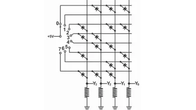
Working Of Diode Rom with Gray Code and Circuit Diagram
Read-only Memory Working Of Diode Rom with Gray Code and Circuit Diagram- Read-only memory or a memory that can only…
-

BCD Encoder circuit diagram and truth table in digital electronics
BCD Encoder BCD Encoder circuit diagram and truth table in digital electronics- An encoder is a digital or logic circuit,…
-

seven segment display truth table and circuit diagram
Seven Segment Display or Indicator Seven segment display is an electronic component, which contains seven LEDs, which are configured together…
-

Decoder logic circuit diagram and operation
Decoder logic circuit diagram and operation A decoder is a type of logic circuit, which converts binary numbers (or binary…
-

Demultiplexer or Distributor with circuit diagram and operation
Demultiplexer or Distributor Demultiplex means “one into many”. A demultiplexer or Distributor is a logic circuit or device, which consists…
-
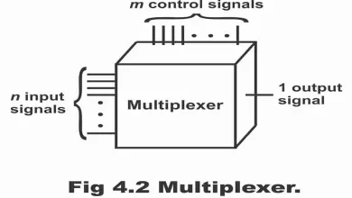
Multiplexer or Data Selector with circuit diagram and operation
Multiplexer or Data Selector A multiplexer is a logic circuit or device, which selects one input line out of numerous…
-

Combinational logic & Data Processing circuits
Combinational logic & Data Processing circuits A combination of inter-connected logic gates, which can perform a specific Boolean function without…
-

Basic comparator operations with circuit diagram examples
Basic Comparator Operations: Basic comparator operations with circuit diagram examples- A device that makes a comparison between the magnitudes or…
-

Half subtractor and Full subtractor with Equations in Digital Electronics
Binary Subtraction Half subtractor and Full subtractor with Equations in Digital Electronics– Similar to the addition of binary digits, following…
-

Half adder and Full adder with Equations in Digital Electronics
Binary Addition Half adder and Full adder with Equations in Digital Electronics- Binary arithmetic is used in digital computers, calculators…