Half subtractor and Full subtractor with Equations in Digital Electronics
Last Updated on November 9, 2022 by Engr. Shahzada Fahad
Table of Contents
Binary Subtraction
Half subtractor and Full subtractor with Equations in Digital Electronics– Similar to the addition of binary digits, following four rules or principles are used as well for the subtraction of binary digits.
0 – 0 = 0
1 – 1 = 0
1 – 0 = 1
10 – 1 = 1 0 -1 with a borrow of 1
During the subtraction of digits, we have sometimes to borrow a digit from the next left column. This borrowed digit is shortly known as Bo (borrow out). In case of binary, we need a borrowed digit at that time when we attempt to subtract 1 from 0. In such a situation, when 1 is borrowed from the next column towards the left, it becomes 10 in the column where it is going to be subtracted. And for this end, last rule of the afore – mentioned four principles is used.
The phenomenon of a binary subtraction can easily be grasped with the help of following example.
Example: – perform the following binary subtractions
(a). 11 – 01 (b). 11 – 10 (c). 101 – 011
Solution: –
(a). 11 – 01 = 10 3 – 1 = 2
(b). 11 – 10 = 01 3 – 2 = 1
(c). 101 – 011 = 010 5 – 3 = 2
Subtractors
A logic circuit, which is used to subtract two binary numbers, is called subtractor. Similar to an adder, a subtractor also has following two types.
- Half–subtractor
- Full–subtractor
Half – subtractor
It is a kind of logic circuit, which has the capacity to subtract two binary digits or bits at the same time and which has two outputs. One of the outputs represents the inputs difference (Di) while other one denotes Borrowed or Bo.
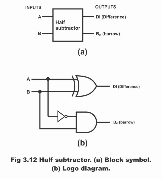
In figure 3.12 (a), block diagram or block symbol of a half – subtractor and in figure (b) its logic diagram has been illustrated. It is clear from the block symbol that a subtractor consists of two inputs (A and B) and two outputs (Di and Bo). Its inputs are on the left whereas its outputs are located on the right side.
Figure 3.12 – half subtractor (a). block symbol (b). logic diagram
In figure 3.13 (a), a binary subtraction table and in figure (b) truth table of a half – subtractor has been shown. In this, B has been subtracted from A on the input side. Similarly, on the output side, we get difference of inputs A and B or Di. If the value of B is higher as compared to A, as can be observed via line 2 of the truth table, in such a situation we will need to borrow one. This has been explicated on the output side by column Bo (Borrow out)
Figure 3.13 – (a). binary subtraction tables (b). truth table for the half – subtractor
With the help of a truth table (which reflects all inputs and outputs) shown in the figure3.13 (b), we can determine the Boolean expressions of a half – subtractor. Remember that operation of a half – subtractor depends on the rules of binary subtraction as has been shown by the truth table. As the difference column represents a difference 1 in case both of the inputs are inverse to each other (analogous to Ʃ column of the half adder). Thus, a XOR gate is used in order to ascertain difference between two bits and the expression of difference or Di just like a half – adder is denoted as follows:
AꚛB = Di
Whereas borrowed output (Bo) can be received via ANDing A with B. Hence, Boolean expression of the borrowed (Bo) column will be as follows:
- B = Bo
If above two equations are combined together in the shape of a logic diagram, a logic circuit of a half – subtractor constructs as has been shown vide figure 3.12 (b).
Full subtractor
A logic circuit comprising three inputs and two outputs, which can simultaneously subtract two bits, is known as full – subtractor. In figure 3.14 (a), block diagram of a full – subtractor has been represented. On the left side of this diagram, three inputs A, B and Bin (Borrowed input) are present, whereas on the right side, two outputs Di and Bo exist. Bin is in fact a “previous borrow” on the input side.
Figure – full subtractor (a). block symbol (b). constructed with half subtractors and an OR gate (c). logic diagram
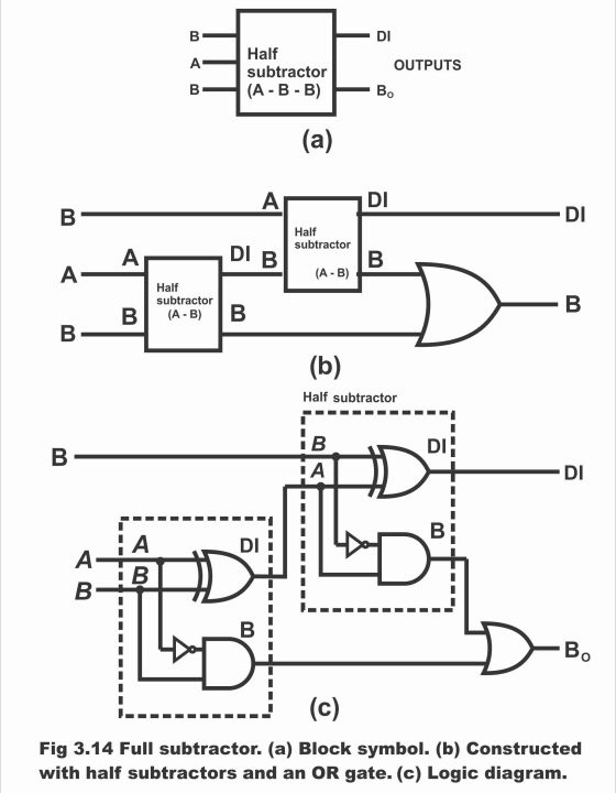
Just like full adders, a full subtractor can also be constructed by means of using two half – subtractors and an OR gate, as has been represented via figure (b). Logic diagram of a full subtractor has been depicted in figure (c).
As a sample, binary subtraction has been illustrated in the figure 3.15 (a). When subtraction of a number of columns of binary digits is desired to be undertaken, in this situation borrowing factor should particularly be kept into mind. In figure (b), truth table of a full – subtractor has been demonstrated, which represents all the possibilities of binary subtraction (A-B-Bin). The method for understanding the truth table of a full – subtractor is as under:
Figure 3.15 – (a). sample binary subtraction problem (b). truth table for a full subtractor
Look at line 2 of the table, wherein A = 0, B = 0 and Bin = 1. For going ahead with subtraction process, we have to borrow 1 from the next stage, by means of which Bo = 1 and 2 is added with A. Thus, Di = 1 (because 2-0-1=1). When A = 0, B = 1 and Bin = 1 (line number 4), we again feel the need to borrow, due to which Bo = 1 and A = 2. Hence, 2 -1 -1 = 0, thus Di = 0. Similarly, when A =1, B = 0 and Bin = 1, (see line number 6) then, A-B-Bin = 0. As a result of which, Bo = 0 and Di = 0. When A = 1, B = 1 and Bin = 1 (last line of the table), we have to borrow 1 once again, hence Bo = 1 and A = 3, thus Di = 1. (i.e. 3-1-1 =1)
Boolean expressions of full subtractor are as under:
Di= A B Bin + A B Bin + A B Bin + AB Bin
Bo= AB + A Bin + B Bin
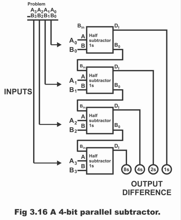
Remember that in full adder and full subtractor, the logic function for sum S and difference Di is identical. Moreover, it must also be inculcated that through cascading (giving ones’ output to the others’ input is known as cascading) 4 full subtractors, we can directly subtract 4-bit numbers i.e. we can subtract B0 B1 B2 B3 from A0 A1 A2 A3, which has been shown in figure 3.16.
Figure 3.16 – A 4- bit parallel subtractor
Adder – subtractor
A logic circuit, which apart from addition, can also perform the function of subtraction, is called adder – subtractor. We have studied addition subtraction detail of binary numbers prior to this, wherein numerous logic circuits have been used for addition and subtraction of various binary numbers. In order to simplify circuits for arithmetic operations in calculating machines (e.g. calculator or computer etc.), attempts are underway to use some type of universal devices, through application of which process of calculations or arithmetic operations becomes simpler and accurate. For this purpose, such circuits are being designed via application of specific techniques, which can be used both as an adder and subtractor (i.e. in this way, the task of addition and subtraction through one circuit becomes possible).
There is a special technique being used in mathematics through which an adder can be used for the subtraction of binary numbers. This technique has been shown in figure 3.17. According to this figure, 6 has been shown as being subtracted from decimal 10 or in case of binary, 0110 being subtracted from 1010. In the figure, first of all decimal subtraction, then binary subtraction and lastly, special arithmetic technique has been shown, by means of which, an adder converts to a subtractor.
Figure 3.17 – an example of 1s complement and end – around carry subtraction
The process of understanding this particular technique is as follows. In special this technique, first write down 1s complement of the binary number (0110) going to be subtracted (i.e. convert all 1s of this number to 0s and convert all 0s of the number to 1s) and then add this complement or inverted binary number with the original (1010) as has been illustrated in the figure. Here, 1s complement of 0110 is 1001. By adding 1010 and 1001, we get the answer 10011. Now on the left side, end around carry of this answer, is brought to 1s (this operation has been shown by an arrow sign in the figure). When end – around – carry is added to the remaining number, the answer actually equals to the difference of the two binary numbers (1010 and 0110). Resultantly, result obtained in this example through 1s complement and end around carry equals to the answer (i.e. 100) obtained through binary subtraction method. That’s the difference between two numbers in this method is also 100 (or the answer equals decimal to decimal 4). Remember, we have been performing addition function via employing this special technique, wherein answer equals to the difference of two binary numbers. Hence, a logic circuit, in which adding two binary numbers under a special technique, results in an answer which is equal to the difference between these two numbers, is called adder – subtractor.
Although the method of 1’s complement and end- around carry apparently seems lengthy and somewhat complicated, however through application of logic circuits, the subtraction function can be undertaken quite easily by means of application of this technique. In this method, an adder is used, which performs the operation of subtraction. The only issue lies in the fact that we have to ascertain as to how to carry out the process of subtraction by means of taking 1’s complement and the end around carry.
Operation
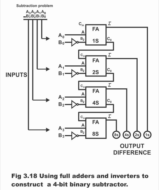
When we use an adder for binary subtraction, (as figure 3.18, in which four such adders on which FA has been written, have been illustrated) which perform the operation of binary subtraction, particularly keep in mind the four inverters B0 B1 B2 B3 given in the figure, which complement or invert a binary number. These inverters provide a 1s complement input on every B input of the full adder (i.e. if the input A value of some adder is 1, the inverter connected with it, makes its input B value 0. On the contrary, if adders’ input is zero, inverter makes its input B1). Adder adds binary numbers (which are denoted as A0 A1 A2 A3 and B0 B1 B2 B3). First full adders’ carry out (Co) is connected with second full adder or 2s carry in (carry input), second full adders’ Co with third or 4s full adder’s Cin, third full adders’ Co with 4th or 8s full adders’ Cin and fourth’s or 8s full adder’s Co back with first or 1s full adders’ Cin through end around carry line, as has been depicted in the figure. The indicators made on the bottom towards the right side reflect difference between binary numbers A0 A1 A2 A3 and B0 B1 B2 B3.
Figure 3.18 – using full adders and inverters to construct a 4 – bit binary subtractor
The following subtraction can be explained from the 4 – bit binary subtraction circuit
A0 A1 A2 A3
-B0 B1 B2 B3
Ʃ0 Ʃ1 Ʃ2 Ʃ3
Suppose we have to subtract decimal 4 from decimal 10 or in case of binary we have to subtract 0100 from 1010 i.e.
Decimal subtraction Binary subtraction
10 – 4 = 6 1010 – 0100 = 0110
In such a situation, A0 A1 A2 A3 and B0 B1 B2 B3 inputs are as follows:
A0 A1 A2 A3 → 1010
B0 B1 B2 B3 → 0100
We replace inverter B present in the circuit with the under – noted 1s complement
B0 B1 B2 B3 → 1011
Thus, full adder performs the following functions
1010
+1011
0101
+1 end- around carry
0110
If light emitting diodes are connected with the output (which reflects the difference) of this circuit made with the help of full adder and inverter, in such a situation LED of 1’s will not irradiate (which reflects low output). However, 2s and 4s LEDs get illuminated (which indicate a high output) Resultantly, subtraction answer becomes clear once we look at the LEDs output.
Thus, subtraction answer on the output will appear as 0110 which is equivalent to decimal 6.
Four–Bit Adder – Subtractor
We know that a full adder can be used both for addition as well as subtraction purposes (i.e. addition and subtraction operations can also be performed within a circuit along with a common binary adder). This objective can be achieved via adding a XOR gate with every full adder. Now we design such a system, which can process both addition as well as subtraction functions.
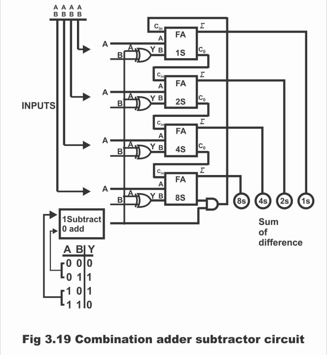
First of all, we begin from the subtractor system shown in the figure 3.18. In order to convert this system into a 4 – bit adder, we will need to cut end around carry line and doing away with the 4 inverters, as can be seen in figure 3.19. According to this figure, 4 XOR gates have been mounted in place of 4 inverters. When input A of XOR gates is binary 0, problem bits pass through the XOR gate without any variation (i.e. when input A is zero, in such a situation the two numbers which are required to be added, its bits pass via XOR without any change), as has been revealed via a table shown below the figure. Thus, by means of setting control at 0, adder – subtractor unit, adds binary number A0 A1 A2 A3 with B0 B1 B2 B3 and result appears on output indicators (up to a sum of 1111). Remember that by setting control on zero (i.e. setting control on addition state) AND gate also turns OFF or AND gate ceases to operate. Thus, connection of end around carry suspends with the first full adder or end around carry signals stop transmitting from AND gates’ output.
When the unit shown in the figure is going to be used as a 4 – bit subtractor, its control must essentially be at position 1. In this situation, XOR gate acts as an inverter for B inputs leading to the full adder, as can be seen via the truth table towards the left on bottom of the figure. AND gate also activates due to having 1 on control (that’s AND gate starts working) and as such information is transmitted back on full adder 1s in the shape of end around carry from full adder 8s. This subtractor subtracts binary input numbers B0 B1 B2 B3 from A0 A1 A2 A3 and difference appears on output indicators in the shape of binary. Remember that in this circuit, 1s complement and end around carry method is used for the purpose of subtraction and XOR gate acts like a complement.
Figure 3.19 – combination adder – subtractor circuit
8 – Bit Adder – subtractor
In figure 3.20, an 8 – bit binary adder – subtractor circuit has been illustrated, which adds or subtracts binary numbers. This circuit is spread across from left to right, i.e. the least significant column of the circuit is towards right whereas the most significant column is towards the left. The carry – out of every full adder (FA) is the carry – in of every next full – adder. Remember that during 8 – bit arithmetic operation, final carry is ignored (because in case of 8 – bit mathematical operation, values remain between 0 – 255, therefore every number supposed to be added or subtracted, must remain between 0 – 255. Further, the answer should also be within a range 0 – 255. If values exceed 255, the 16 – bit arithmetic operation should be used. While using the 8 – bit arithmetic operation, if the answer as a result of addition is greater than 255, an overflow occurs and a carry moves into the 9th column. There is just one circuit in most of the microprocessors, which is known as carry flag. This circuit, provides information sensing carry in the 9th column, that 8 – bit answer is invalid. That’s the reason, final carry is generally being ignored during an 8 – bit arithmetic operation)
Figure 3.20 – binary adder – subtractor

Addition
The function of addition is represented as under:
A0 A1 A2 A3 A4 A5 A6 A7
+ B0 B1 B2 B3 B4 B5 B6 B7
S0 S1 S2 S3 S4 S5 S6 S7
During addition, as SUB signal is maintained at low state, therefore binary numbers B0 to B7, pass through the control inverter without any sort of variations, thus full adder produces correct output sum. This happens as a result of bits being added in every column and the movement of carriers to the next higher column. For example, starting from LSB, full adder adds A0, B0 and SUB, due to which the sum of S0 results and carry out shifts to the next higher full loader. Next higher full adder then produces S1 and Carry – out through adding A1, B1 and Carry – in. Exactly in the same manner, other full loaders also perform the task of addition, and an accurate sum appears on output line.
For example, suppose that +125 and -67 are required to be added, then the values of A0 – A7 and B0 to B7 are equal to the following:
A7 – A0 = 0111 1101
B7 – B0 = 1011 1101
As SUB = 0 during the addition operation, therefore the value carry – in of least significant column is zero i.e.
0 ← SUB
0111 1101
+1011 1101
?
Here, full – adder performs the following arithmetic operation
0 +1 +1 = 0 with a carry of 1
Carry out of first full adder is carry in of the second full adder i.e.
1 ← carry
0111 1101
+1011 1101
0
By adding in the 2nd column,
1 + 0+ 0 = 1 with a carry of 0
This carry is received by the 3rd full adder
0 ← carry
0111 1101
+1011 1101
10
Similarly, remaining full adders add their 3 – input bits, until we arrive at last full adder. Hence
1 ← carry
0111 1101
+1011 1101
0011 1010
In case the most significant bit (MSB) lying on the left end, receives carry – in, then full adder presents the following answer to the addition
1 + 0+ 1 = 0 with a carry of 1
After this final carry, the function of addition gets completed i.e.
0111 1101
+1011 1101
10011 1010
As this final carry is ignored in an 8 – bit arithmetic operation, thus addition answer is as under:
S7 … S0 = 0011 1010
This answer is equivalent to decimal +58, which is a sum of numbers +125 and -67
ii). Subtraction
The process of subtraction is represented through the following method.
A7 A6 A5 A4 A3 A2 A1 A0
-B7 B6 B5 B4 B3 B2 B1 B0
S7 S6 S5 S4 S3 S2 S1 S0
Remember that the SIB signal is kept on high state during subtraction, as a result of which 1’s of control inverter B0 to B7 produces complement. Moreover, as SUB signal is received on the full adder as Carry – in, therefore circuit process data in the following method
1 ← SUB
A7 A6 A5 A4 A3 A2 A1 A0
+B7 B6 B5 B4 B3 B2 B1 B0
S7 S6 S5 S4 S3 S2 S1 S0
When A7 … A0 = 0, circuit produces 2’s complement of B7 … B0, which is added into the 1’s complement of B7 … B0. (when 1 is added to 1’s complement, the binary number received as a result of this operation is called 2’s complement i.e.
(2’s complement = 1’s complement +1). When A7 … A0 are not equal to 0, then effects A7 … A0 and B7 … B0 equal to the sum of 2’s complement.
For example, suppose that we have numbers +82 and +17. In such a situation,
A7 … A0 = 0101 0010
B7 … B0 = 0001 0001
Control inverter B’ s 1’s produces complement which is 1110 1110. As during subtraction, SUB = 1, hence circuit performs the following function of addition
1←SUB
0101 0010
+1110 1110
10100 0001
As final carry is ignored in an 8 – bit arithmetic operation, therefore the answer becomes
S7 … S0 = 0100 0001
This answer is equal to decimal +65, which is the arithmetic difference found between numbers +82 and +17.
Previous Topic: Half adder and Full adder with Equations in Digital Electronics
Next Topic: Basic comparator operations with circuit diagram examples
For electronics and programming-related projects visit my YouTube channel.
Discover more from Electronic Clinic
Subscribe to get the latest posts sent to your email.


