Basic comparator operations with circuit diagram examples
Last Updated on November 10, 2022 by Engr. Shahzada Fahad
Basic Comparator Operations:
Basic comparator operations with circuit diagram examples- A device that makes a comparison between the magnitudes or sizes of two binary numbers and also expresses their reciprocated relation, is called a comparator or magnitude comparator, or digital comparator.
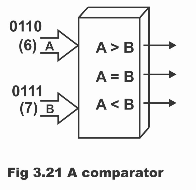
In other words, the comparator is a logic circuit, which by means of making a comparison between two digital numbers reveals whether the magnitude of one number is higher, low, or equal to the magnitude of another number. In simple words, a comparator circuit determines whether both numbers (A and B) are equal or not. If both numbers are equal, a low or 0 output is received from the comparator, whereas the comparator provides a high or binary 1 output as a result of the difference between the two numbers. For example, if A = 0110 (decimal 6) and B = 0111 (decimal 7), then output A B will be high and the other two outputs (i.e. A B and AB) will be low, as has been demonstrated in the figure. Thus, a comparator makes a comparison between two binary numbers and tells that a number is large as compared to the other, small, or both are mutually equal.
Figure 3.21 – a comparator
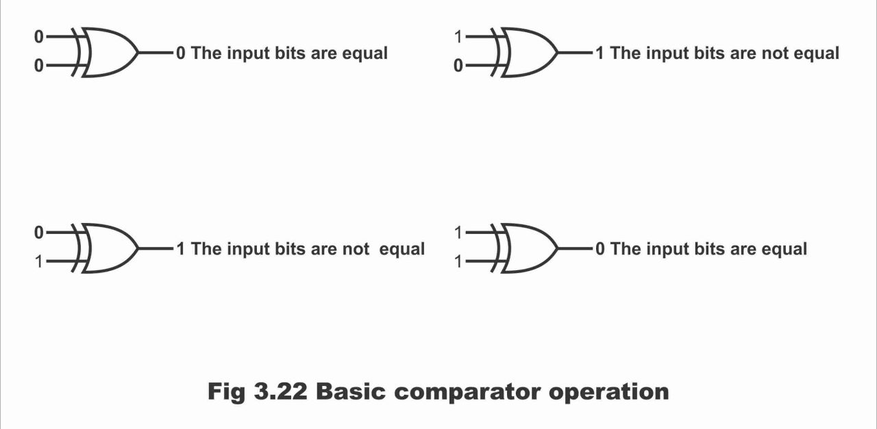
As it is a feature of an exclusive OR gate (XOR) that its output is 1 at a time when two of its inputs are un-equivalent (i.e. when both inputs are different, then the output of the XOR gate is 1 or high). And the output of the XOR gate is low or 0 when both its inputs are mutually equal or similar. As a result of this virtue of an XOR gate, it is used as a basic comparator. In figure 3.22, the basic operation of a two-bit comparator has been displayed by means of using an XOR gate.
Figure. 3.22 – Basic comparator operation
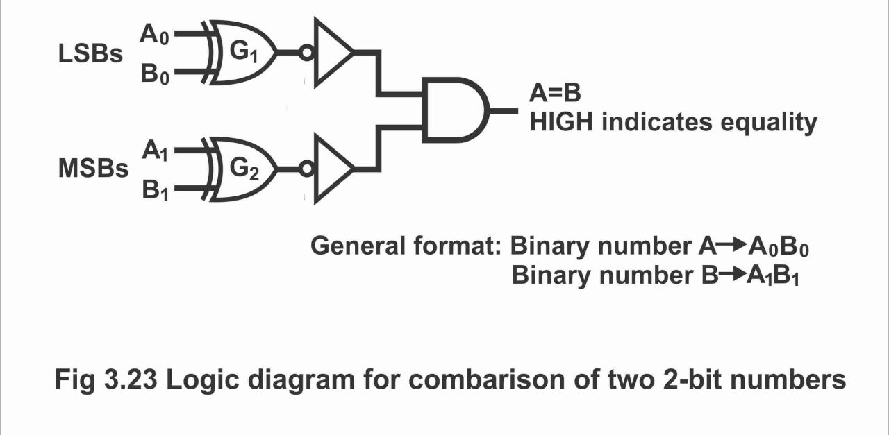
If every number consists of two bits, and comparison of such two numbers is desired, then need for an XOR gate (Exclusive OR) arises. In such a situation, comparison of two least significant bits (LSBs) of the two numbers is done through gate G1 while comparison of two most significant bits (MSBs) is done via gate G2. As can be seen in figure 3.23. if both numbers are equal, its related bits are also equal or same or similar and in such a situation, output of XOR gate is 0. However, if corresponding sets of these bits are not mutually equal, the output of XOR gate is binary 1. In order to produce a single output, which represents whether two numbers are equal or unequal, two inverters and an AND gate is used with both XOR gates, as has been illustrated in the figure.
The output of every XOR gate connects with input of AND gate by means of inverting through an inverter. When both inputs of XOR gate are equal (i.e. 00 or 11), binary 1 condition emerges on both inputs of AND gate and thus, binary 1 is also received on AND gate output. However, as both the numbers are unequal, one or both sets of the corresponding bits become unequal as well. And due to a 0 on any one input of AND gate, 0 is also found on its output (i.e. in situation of different inputs on every XOR gate, or in case of equal inputs on one gate and unequal inputs on the other, at least one input on AND gate becomes zero, due to which output of AND gate also becomes zero). As such, presence of binary 1 on output of AND gate represents both numbers being equal and presence of binary 0 on AND gate output, depicts both numbers being unequal or opposite. It must be remembered that XOR gate and inverter can also be replaced with (X NOR) gate.
Figure 3.23 – logic diagram for comparison of two 2 – bit numbers
A basic comparator circuit can be expanded to any number of bits (or from two bits to numerous bits) as has been elucidated via a two 4 – bits comparator circuit in figure 3.24. However, irrespective of the number of bits, the condition of AND gate remains as it is that if both numbers are mutually equal, the corresponding bits of these numbers should also be equal or same. The circuit shown in figure 3.24 is a two-number circuit, every number of which comprises 4 – bits. It means that one binary number is A3 A2 A1 A0 and it is called number A, whereas other binary number is B3 B2 B1 B0, which is called number B. Every pair of bits (e.g. A1 B1, A0 B0 etc.) is applied on a X- NOR gate. When both numbers are mutually equal, output of XNOR gate is binary 1 and when all inputs of AND gate are binary 1, its output becomes also binary 1, which indicates that both numbers or words are mutually equal. However, contrary to this, in case inputs of XNOR are unequal, output becomes binary 0, which implies that both numbers are not mutually equivalent.
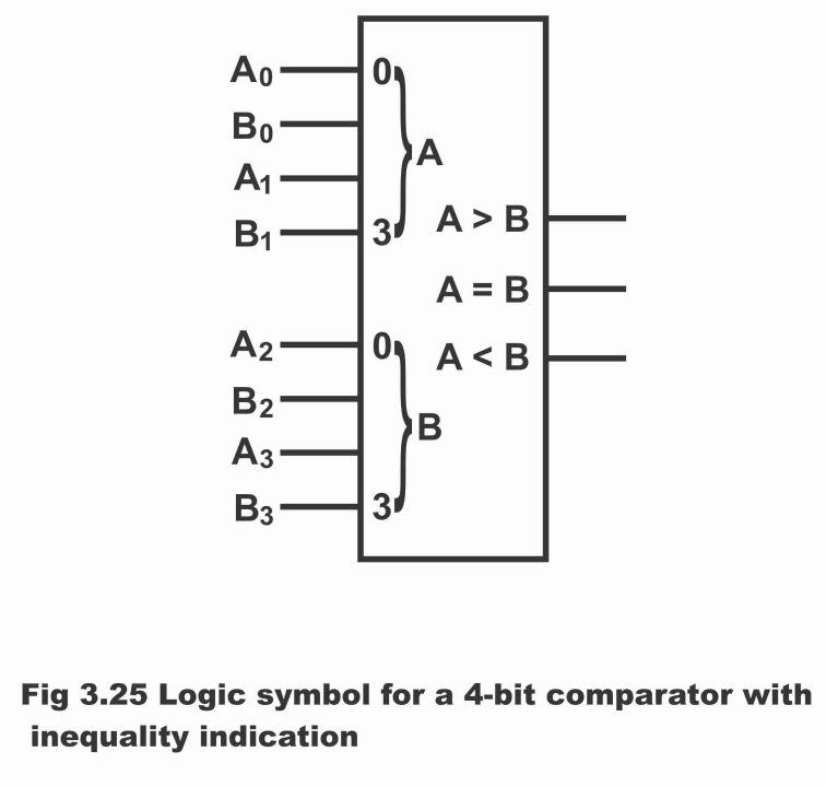
Apart from indicating an equal output, a number of such integrated circuits are now available on commercial basis, which by means of providing additional output, indicate that which one of the two numbers being compared is large or which one is small i.e. apart from providing same output, such integrated circuits (wherein a circuit has been manufactured by means of connecting several circuits) also produce two additional outputs. One of these outputs indicates that which one of the two numbers is large whereas the other output specifies which one of the two numbers is small. In figure 3.25, block diagram of such type of a 4 – bits comparator has been illustrated, which is in the form of an integrated chip. For example, if number A is larger than number B, then output will be AB binary 1 or high. On the other hand, if number B is large as compared to A, then output AB will be binary 1. Such type of comparators is mostly designed for making a comparison between two 4 – bits binary numbers.
Figure 3.24 – logic diagram for the comparison of two 4 – bit numbers A3 A2 A1 A0 and B3 B2 B1 B0
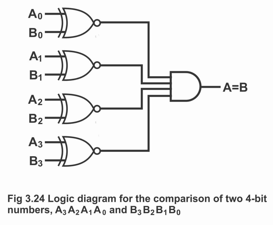
Figure 3.25 – logic symbol for a 4 – bit comparator with inequality indication
Previous Topic: Half subtractor and Full subtractor with Equations in Digital Electronics
Next Topic: Combinational logic & Data Processing circuits
For electronics and programming-related projects visit my YouTube channel.
Discover more from Electronic Clinic
Subscribe to get the latest posts sent to your email.


