Input Overvoltage protection for Arduino Inputs using a Zener Diode
Input Overvoltage Protection Description:
Input Overvoltage protection Project is based on how to protect your Arduino’s Analog Input Pins and Digital input Pins against Overvoltage using a Zener Diode. The technique I am going to explain in this Tutorial can be used in any Electronics circuit.
For the best understanding, I am going to use Arduino Uno in this tutorial and will design a circuit to protect the Arduino Input Pins against the overvoltage as you know voltages greater than 5 volts can damage the Arduino Pins. The electronic component which is most commonly used throughout the world against the overvoltage is the Zener diode. So this Tutorial is entirely based on the Zener Diode.
In this tutorial, I will try to cover the maximum things like for example
- What is a Zener diode?
- It’s characteristics
- Symbol
- Datasheet
- Working
- Application
- And Zener diode practical use in an electronics circuit
0-25V voltage Sensor-based Voltage Monitoring:
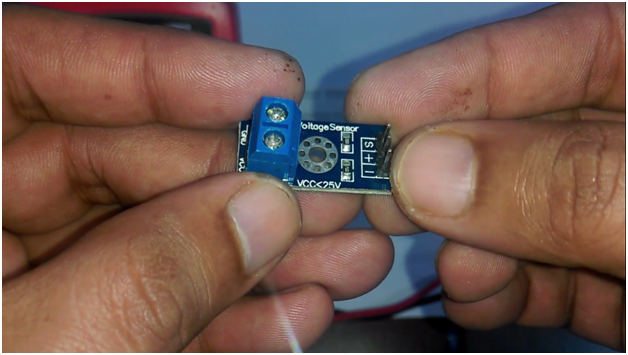
A few months back I uploaded a tutorial on the Arduino voltage monitoring system using 0 to 25v voltage sensor, this voltage sensor is capable of measuring the voltage ranging from 0.02445v to 25volts dc. At 25v we get exactly 5v. As you know my friends the Arduino’s maximum analog voltage is 5v.
But what if we increase the voltage above 25v the output voltage will also increase and so will damage the analog pin of the controller. So this Voltage sensor has no protection against the overvoltage and can easily damage the Arduino Input Pins.
So that’s why I decided to make another Tutorial which can provide perfect protection against the Overvoltages.
Amazon Links:
Other Tools and Components:
Super Starter kit for Beginners
PCB small portable drill machines
DISCLAIMER:
Please Note: these are affiliate links. I may make a commission if you buy the components through these links. I would appreciate your support in this way!
Zener Diode:
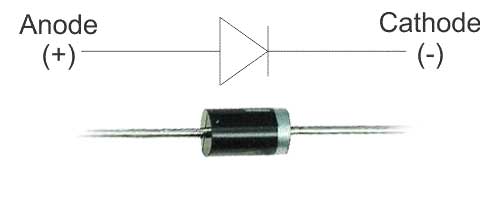
This is the Symbol of a Zener diode. A Zener diode is a silicon semiconductor device that permits current to flow in both forward and reverse direction.
Zener Diode not only allows the flow of current when used in forward bias, but they also allow the flow of current when used in the reversed bias so far the applied voltage is above the breakdown voltage known as the Zener Breakdown Voltage. Or in other words, the Breakdown voltage is the voltage, on which Zener Diode starts conducting in reverse direction. The Zener break down voltage is denoted by Vz.
In normal diodes, the breakdown voltage is very high and the diode gets damaged totally if a voltage above the breakdown diode is applied, but in Zener diodes, the breakdown voltage is not as high and does not lead to permanent damage of the Zener diode if the voltage is applied.
As the reverse voltage applied to the Zener diode increases towards the specified Breakdown Voltage (Vz), a current starts flowing through the diode and this current is known as the Zener Current and this process is known as Avalanche Breakdown. The current increases to a maximum and get stabilized. This current remains constant over the wider range of applied voltage and allows the Zener diode to withstand higher voltage without getting damaged. This current is determined by the series resistor.
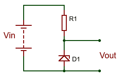
A resistor, R1 is connected in series with the Zener diode to limit the amount of current flowing through the diode and the input voltage Vin (Which must be greater than the Zener voltage) is connected across as shown in the image and the output voltage Vout, is taken across the Zener diode with Vout = Vz (Zener Voltage).
Care must be taken when selecting the value of resistor R1, as a small value resistor will result in a large diode current when the load is connected and this will increase the power dissipation requirement of the diode which could become higher than the maximum power rating of the Zener and could damage it.
The value of the resistor to be used can be determined using the formula below.
R1 = (Vin – VZ) / IZ
Where;
R1 is the value of the series resistance.
Vin is the input voltage.
Vz which is same as Vout is the Zener voltage
And Iz is the Zener current.
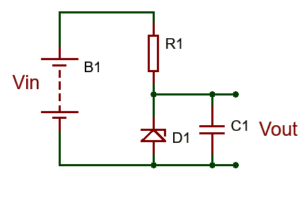
By using this formula it becomes easy to ensure that the value of the resistor selected doesn’t lead to the flow of current higher than what the Zener can handle. One little problem experienced with Zener diode-based regulator circuits is that the Zener sometimes generate electrical noise on the supply rail, this problem may be solved by the addition of a large value decoupling capacitor across the diode. This helps stabilize the output of the Zener diode.
Zener diode datasheet specifications
Zener diodes vary in specifications such as nominal working voltage, power dissipation, maximum reverse current, and packaging. Some commonly used specifications include:
Voltage Vz: The Zener voltage refers to the reverse breakdown voltage—2.4 V to about 200 V; can go up to 1 kV while the maximum for the surface-mounted device (SMD) is about 47 V).
Current Iz (max.): Maximum current at the rated Zener voltage Vz—200 uA to 200 A).
Current Iz (min.): Minimum current required for the diode to break down—5 mA and 10 mA.
Power rating: The maximum power the Zener diode can dissipate; given by the product of voltage across the diode and the current flowing through. Typical values are 400 mW, 500 mW, 1 W, and 5 W; for surface mounted, 200 mW, 350 mW, 500 mW, and 1 W are typical.
Voltage tolerance: Typically ±5%.
Temperature stability: Diodes around 5 V have the best stability.
Zener diode applications
Zener diodes are used for voltage regulation, as reference elements, surge suppressors, and in switching applications and clipper circuits. Enough with the theory lets practically use this with the voltage sensor against overvoltage.
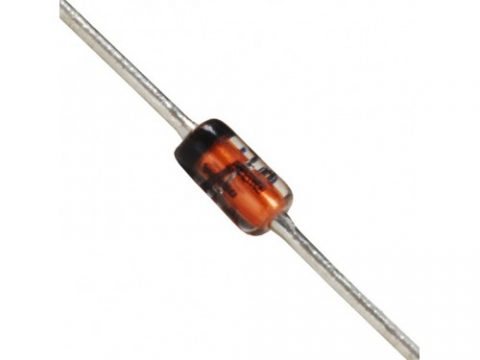
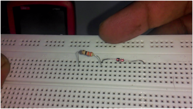
This is a 5.1v Zener diode. Let’s first use this with a 12v power supply.
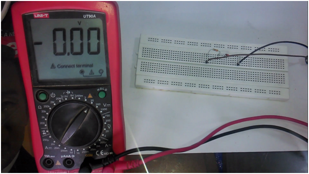
As you can see a 330-ohm resistor is connected in series with the Zener diode. Connect a 12v wire with the resistor and connect the ground wire with the Zener diode anode side.
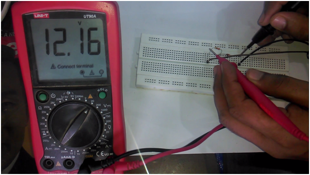
Turn on the digital Multimeter and check the input voltage which is 12.16 volts.
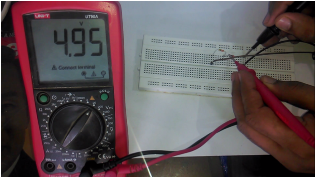
Now check the Zener diode voltage, which is 4.95volt, perfect.
Now let’s use this Zener diode with this 0 to 25v voltage sensor.
Connect two jumper wires with the Vcc and GND of the voltage Sensor; this is where we connect the input voltage. Connect two jumper wires with the S and minus pins of the voltage sensor.
Connect the Input supply with the Vcc and GND of the voltage sensor with the 12v power supply. Connect the red wiring coming from the s pin of the voltage sensor with the resistor, and connect the black wire coming from the minus pin of the voltage sensor with the anode of Zener diode.
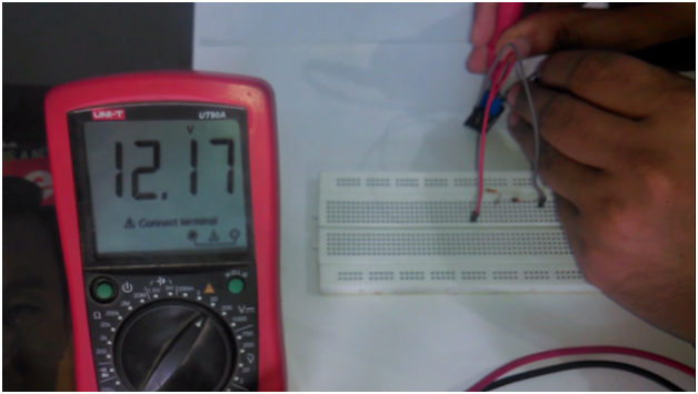
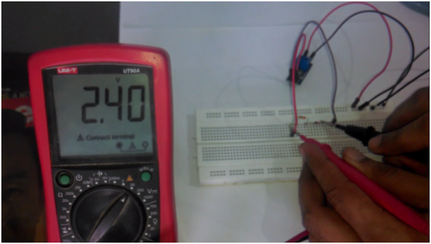
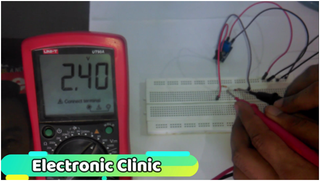
The input voltage to the voltage sensor is 12.17volts. The output of the voltage sensor is 2.40 volts.
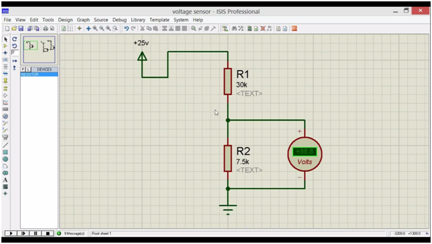
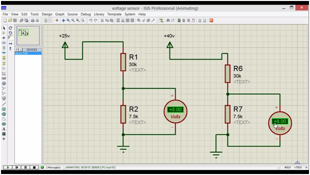
This voltage sensor simply consists of two resistors connected in series.
Let’s solve this.
R1 = 30k ohm
r2 = 7.5k ohm
we can find out the Output voltage, by using the voltage divider formula which is
Vout = ( r2 x vin ) / ( r1 + r2)
vout = (7.5 x 1000 x 12.17) / (30k + 7.5k)
vout = 91275 / 37500
vout = 2.434 which is approximately equal.
At 25v input this sensor will give 5volt.
The voltage available at the Zener output is exactly equal to the voltage sensor output. So at voltages less than the Zener breakdown voltage, the Zener diode behaves like as if it’s not even present. So at this point we have double protection, the 12v supply voltage was reduced to 2.4volt using the voltage sensor and the use of Zener diode at the output of this voltage sensor further increases the protection.
let’s say in a very rare case the voltage increases above 25v, due to which the output voltage of the sensor also increases above 5v, let’s say 10v, 30v, or even more, this Zener diode will keep the voltage at 5v or less. At this point my aim is not to get the exact 5v, but my aim is to make sure that the voltage at the analog input of the controller doesn’t increase above 5volt.
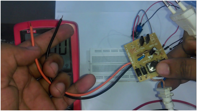
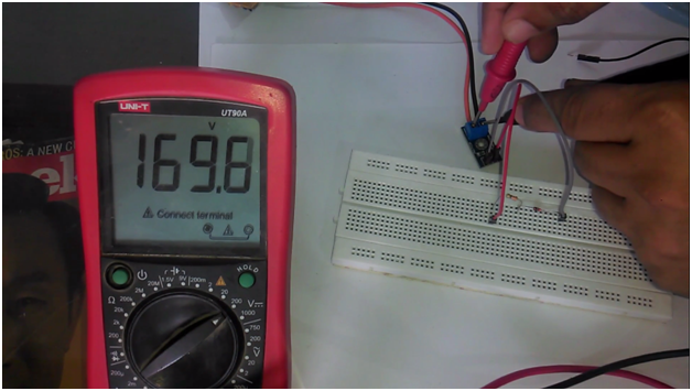
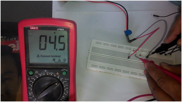
This is a high voltage dc power supply, it directly converts ac into dc, make sure while using such type of power supply never touch the PCB and wires, as it can result in a heavy electric shock and can be really dangerous. Let’s connect this with the voltage sensor, connect the red wire with the Vcc of the voltage sensor and connect the black wire with the ground. Set the multimeter at 200volt as you can see the input voltage is even greater than 150volt dc.
While the output at the Zener diode is 4.5volt. which is less than 5volts.
This voltage change is due to the high voltage as our aim is not to regulate this high voltage at 5v, but to protect our circuit. So the use of voltage sensor and Zener diode can give you double protection against overvoltages. So for the input overvoltage protection Zener Diode is the best choice. For the Step by Step explanation and Practical demonstration watch video Tutorial given below.
input overvoltage protection Video Tutorial:
Top 10 Arduino Projects with Tutorials:
https://www.electroniclinic.com/top-10-arduino-projects-2019-final-year-engineering-project-ideas-electricalelectronics/
Top 10 IoT Projects with Tutorials:
https://www.electroniclinic.com/top-10-arduino-iot-projects-2019-2020-with-tutorials-iot-projects-using-arduino/

