ESP32 LoRa Oled, TTGO LoRa32 SX1276 with Arduino, Range Test
Table of Contents
TTGO LoRa32 with Arduino:
ESP32 LoRa Oled, LILYGO TTGO LoRa32 SX1276 with Arduino, Range Test- I have finally received the parcel that I was eagerly waiting for.
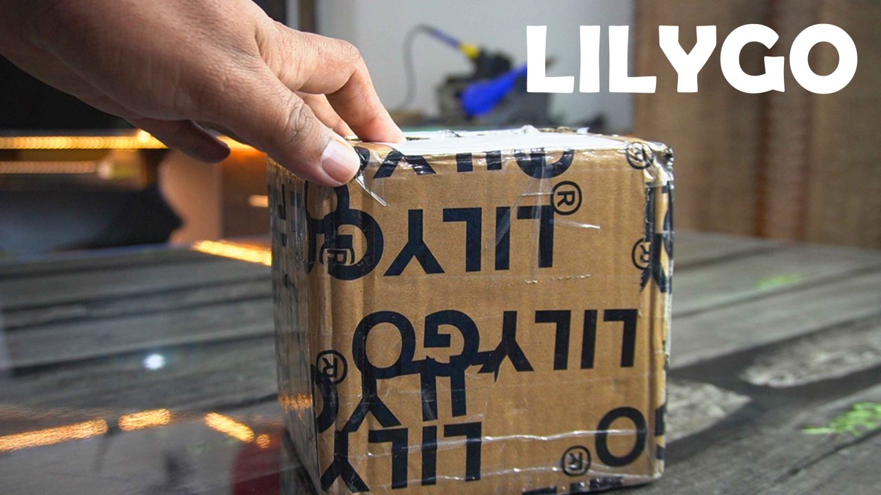
So, let’s go ahead and start the unboxing. The first thing I found inside this was this business card.
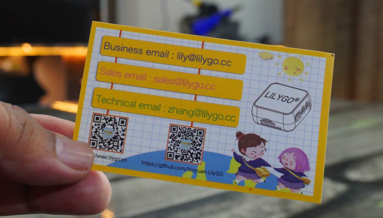
If you have any business-related, sales-related, or technical questions, you can contact them through the email IDs provided on this card. You can find the official LILYGO website link on the back of the card. I have personally visited their website, and they have an amazing collection of development boards, displays, wearable kits, and many other basic modules. Anyway, inside the box, I also found a pair of these plastic boxes.
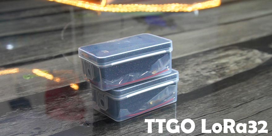
Let’s check what’s inside these boxes. The packing is quite impressive.
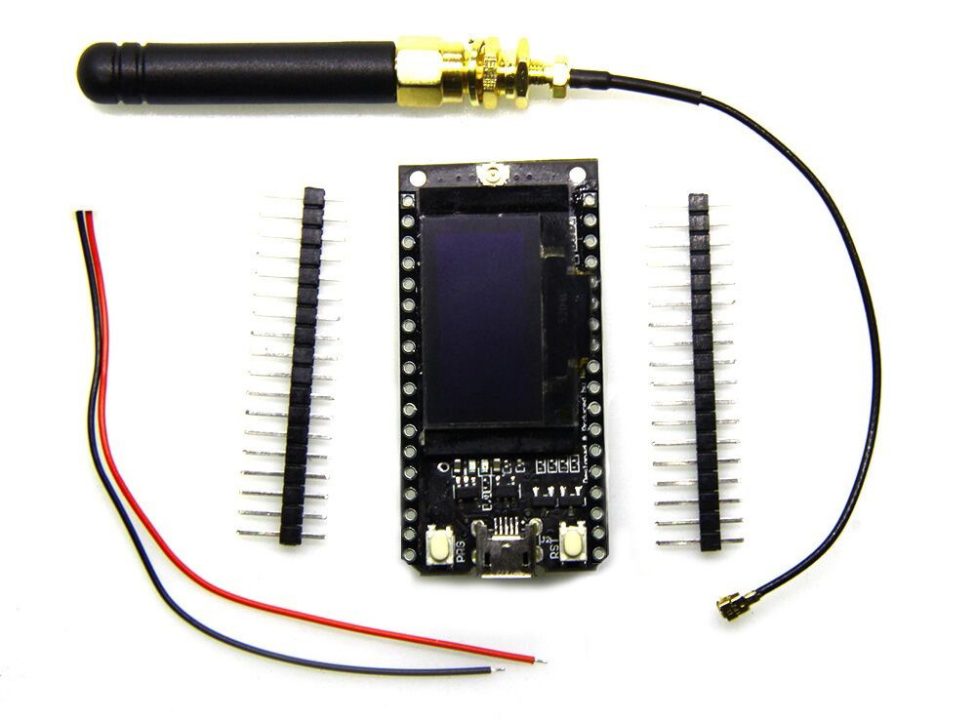
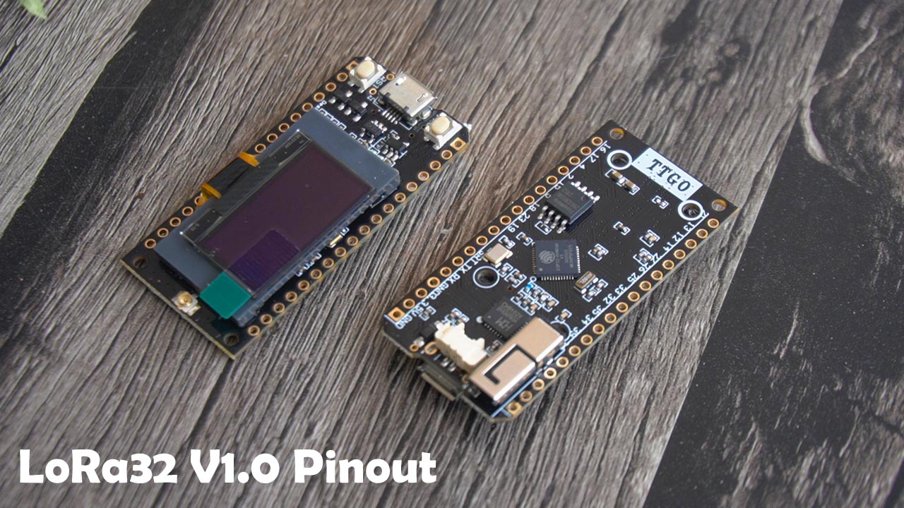
Inside this box we have a LoRa32 V1.0 868Mhz, LoRa Antenna, male headers, and a battery connector JST 2 pin 1.25mm.
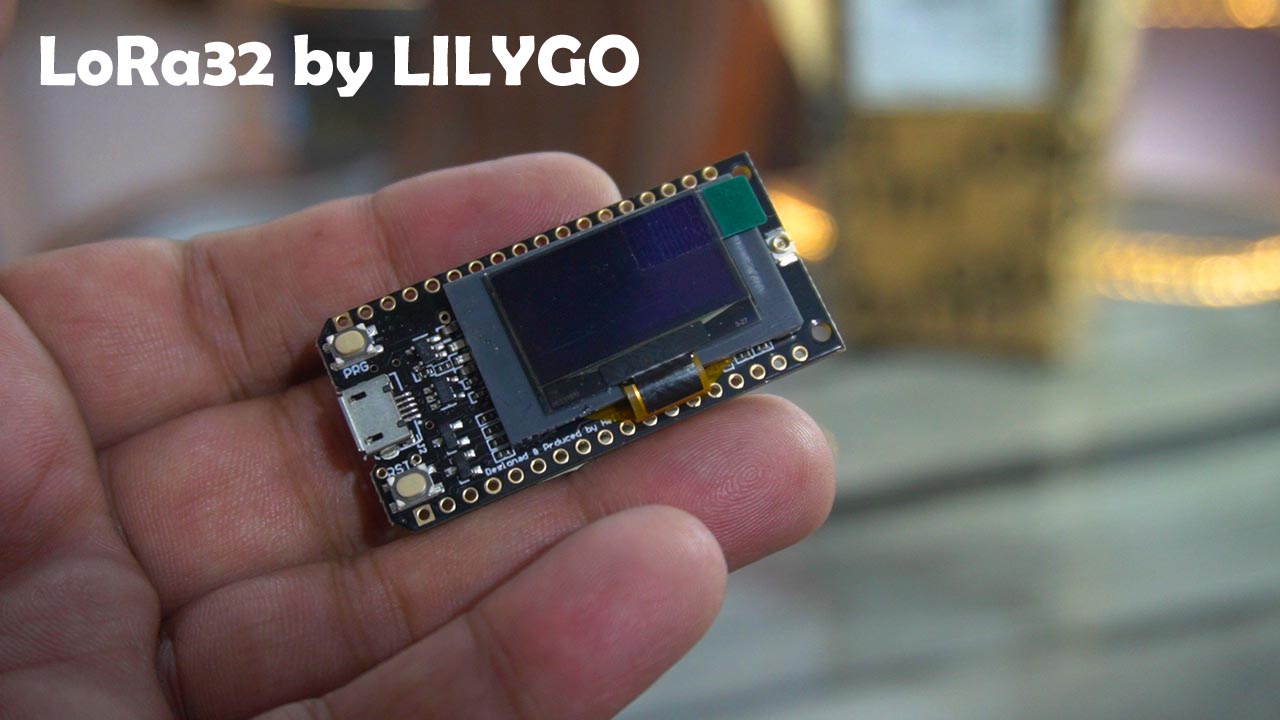
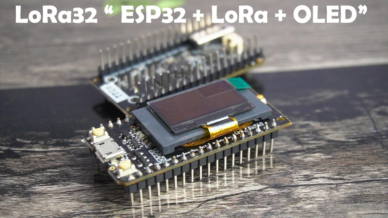
So, guys, this is the TTGO LoRa32 868MHz V1.0 based on the SX1276 chip combined with ESP32 WiFi + Bluetooth and an I2C supported 0.96-inches OLED display module. So many things on this tiny board, its quite impressive.
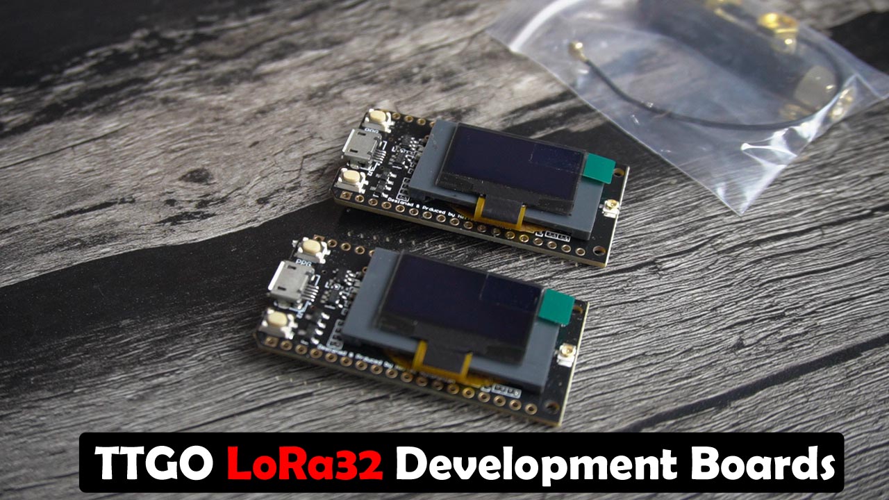
Anyway, I have received two of these development boards, and as you can see, both modules are identical. With the help of these development boards, now I can easily test ESP32 and LoRa-based projects. I don’t even need to attach the OLED display module. You can use any of these modules as a receiver or transmitter. As these development boards are based on the ESP32 WiFi + Bluetooth, you can make IoT gateways and use your cellphone to send and receive messages, control, and monitor different types of loads and sensors.
Well, I have already used ESP32 and LoRa in many projects before. But this time, I am very excited about the communication range of these modules. Previously, I was using LoRa SX1278 transceiver modules, which had a range of around 118 meters, and I was able to control some loads. In this test, both LoRa modules were in line of sight. But when both modules are not in line of sight, the communication range drops to around 50 meters, which is quite low.
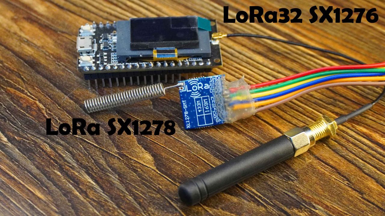
Just look at the size difference of these two LoRa modules, this one is 433Mhz SX1278 and the TTGO LoRa32 is based on the SX1276 and is 868MHz. Later in this article, I will perform a complete range test.
Amazon Links:
TTGO LoRa32 V1.0 / Official product link
Other Tools and Components:
Super Starter kit for Beginners
PCB small portable drill machines
*Please Note: These are affiliate links. I may make a commission if you buy the components through these links. I would appreciate your support in this way!
TTGO LoRa32 Specifications:
- The operating voltage is 3.3 to 7 volts
- It is based on ESP32 WiFi + Bluetooth.
- Operating temperature range is from -40 to 90 degrees Celsius.
- Support for Sniffer software protocol analysis, Station, SoftAP, and Wi-Fi Direct modes
- Data rates: 150 Mbps @ 11n HT40., 72 Mbps @ 11n HT20, 54 Mbps @ 11g, 11 Mbps @ 11b
- Transmit power is 19.5 dBm @ 11b, 16.5 dBm @ 11g, and 15.5 dBm @ 11n
- Receiver Sensitivity is up to -98 dBm
- UDP sustained throughput is 135 Mbps.
- It has an onboard lithium battery charging circuit and it can be programmed using the Arduino IDE.
- The board also has IPEX interface for connecting the 868 MHz Antenna.
- The board also has a Red Light power indicator and a Blue light connected to IO25 which is programmable.
- The LoRa32 board also has CH9102X.
LoRa 1276 Vs LoRa 1278:
LoRa 1276 and LoRa 1278 are both LoRa radio modules produced by the company Semtech, which use the LoRa modulation technology for long-range, low-power wireless communication.
The main difference between the two modules is their frequency bands:
LoRa 1276 operates on the 868 MHz band (EU) or 915 MHz band (North America).
LoRa 1278 operates on the 433 MHz band (EU) or 470 MHz band (China).
433E6 for Asia
866E6 for Europe
915E6 for North America
In addition to the frequency bands, there are some other differences between the two modules:
The LoRa 1278 has a higher output power than the LoRa 1276, with a maximum transmit power of 100mW compared to 22dBm (158mW) for the LoRa 1276.
The LoRa 1278 has a lower receiver sensitivity than the LoRa 1276, which means that it can receive weaker signals.
When choosing between these two modules, it’s important to consider the frequency band that is legal in your region and the specific requirements of your application. If you need a higher output power, the LoRa 1278 may be a better choice, but if you need better range or the ability to receive weaker signals, the LoRa 1276 may be the better option.
CH9102X:
TTGO LoRa32 has an onboard CH9102X. CH9102X is a USB to UART/I2C/SPI/TTL/PS2 interface converter chip produced by WCH (Nanjing Qinheng Microelectronics Co., Ltd.). It allows a microcontroller or other electronic device to communicate with a computer via USB.
The CH9102X chip supports multiple serial communication protocols, including UART, I2C, SPI, TTL, and PS2. It also supports multiple baud rates, data formats, and parity settings, making it a versatile solution for a wide range of applications.
The chip is typically used in embedded systems, industrial automation, instrumentation, and other electronic devices that require communication with a computer or other host system. It can also be used for programming and debugging microcontrollers and other devices.
WCH provides drivers for Windows, Linux, and Mac OS, making it easy to integrate the CH9102X chip into various operating systems. The chip is available in a variety of packages, including QFN32, SSOP28, and DIP28, to suit different design requirements.
TTGO LoRa32 Pins Diagram:
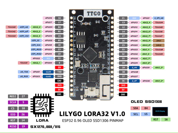
You can download this Pinout diagram from the LILYGO official website. You can see the SSD1306 Oled display module SDA and SCL pins are connected to the Pins 04 and 15. And the SX1276 LoRa transceiver module MOSI, SCLK, CS, DIO, RST, and MISO pins are connected to pins 27, 5, 18, 26, 14, and 19. All the other pins are clearly labeled. You can see the 5V and 3.3V pins are available on both sides. We have got three GND pins. And all these other GPIO pins can be used for connecting input and output devices.
It would have been perfect if the pins labeling was done on the top side. Because once its inserted into the breadboard then the pins labels are gone. Anyway, let’s go ahead and solder the male headers and then I will explain the interfacing and programming. Anyway, while doing the soldering be very careful not to damage the Oled strip.
Male headers are soldered on both the modules and now, let’s go ahead and take a look at the circuit diagrams.
Altium Designer + Altium 365 + Octopart:

Altium 365 lets you hold the fastest design reviews ever. Share your designs from anywhere and with anyone with a single click. it’s easy, leave a comment tagging your teammate and they’ll instantly receive an email with a link to the design. Anyone you invite can open the design using a web browser. Using the browser interface, you’re able to comment, markup, cross probe, inspect, and more. Comments are attached directly to the project, making them viewable within Altium designer as well as through the browser interface. Design, share, and manufacture, all in the same space with nothing extra to install or configure. Connect to the platform directly from Altium Designer without changing how you already design electronics. Altium 365 requires no additional licenses and comes included with your subscription plan.
Get real-time component insights as you design with Octopart built into Altium 365. Octopart is the fastest search engine for electronic parts and gives you the most up-to-date part data like specs, datasheets, cad models, and how much the part costs at different amounts etc. Right in the design environment so you can focus on your designs. Start with Altium Designer and Activate Altium 365. Search for electronic parts on Octopart.
TTGO LoRa32 Transmitter Side:
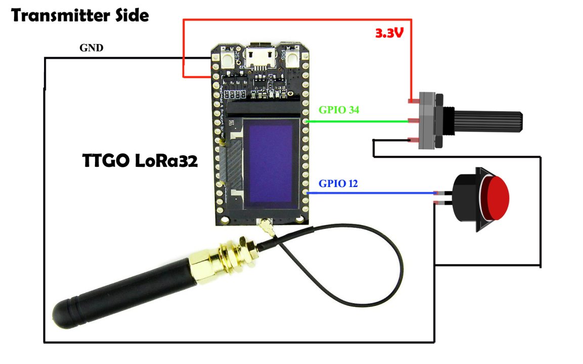
On the Transmitter side, I have connected a potentiometer and a button. The Potentiometer middle leg is connected to the GPIO34 and the other two legs of the Potentiometer are connected to the 3.3V and GND pins. While the button is connected to the GPIO12.
TTGO LoRa32 Receiver Side:
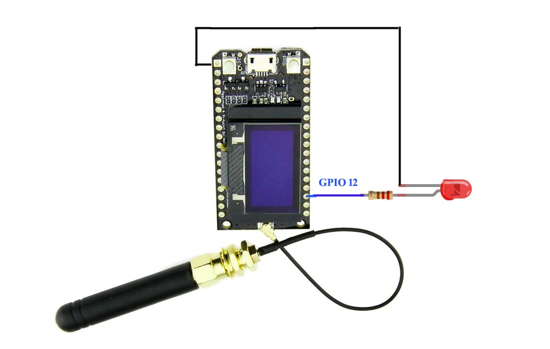
On the receiver side I have connected an LED. And I am going to control this LED using a button on the transmitter side
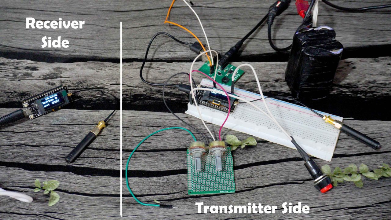
I have connected everything as per the circuit diagrams. This is the transmitter side and this is the receiver side. On the transmitter side I am going to use this button to control this LED on the receiver side. And I am also going to send the Potentiometer value to the receiver where it will be printed on the Oled display module. So, its just a basic setup to explain how to establish wireless communication and most importantly to check the communication range. Anyway, let’s go ahead and take a look at the transmitter and receiver side programming.
LoRa32 Programming:
If you already have an ESP32 board installed, then there shouldn’t be any problem, you just need to install these libraries.
But if you don’t have an ESP32 board installed, then you need to install it first, and the complete process is explained in the article Getting started with ESP32 WiFi + Bluetooth Module.
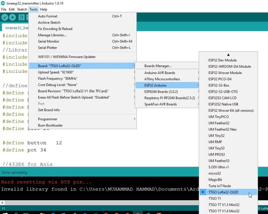
Anyway, once you install the ESP32 board then you can go to the Tools menu, Board, ESP32 Arduino, and from the boards list you can select TTGO LoRa32-OLED.
TTGO LoRa32 Transmitter Side Code:
|
1 2 3 4 5 6 7 8 9 10 11 12 13 14 15 16 17 18 19 20 21 22 23 24 25 26 27 28 29 30 31 32 33 34 35 36 37 38 39 40 41 42 43 44 45 46 47 48 49 50 51 52 53 54 55 56 57 58 59 60 61 62 63 64 65 66 67 68 69 70 71 72 73 74 75 76 77 78 79 80 81 82 83 84 85 86 87 88 89 90 91 92 93 94 95 96 97 98 99 100 101 102 103 104 105 106 107 108 109 110 111 112 113 114 115 116 117 118 119 120 121 122 123 124 125 126 127 128 129 |
#include <SPI.h> #include <LoRa.h> //Libraries for OLED Display #include <Wire.h> #include <Adafruit_GFX.h> #include <Adafruit_SSD1306.h> //define the pins used by the LoRa transceiver module #define SCK 5 #define MISO 19 #define MOSI 27 #define SS 18 #define RST 14 #define DIO0 26 #define button 12 #define pot 34 //433E6 for Asia //866E6 for Europe //915E6 for North America #define BAND 866E6 //OLED pins #define OLED_SDA 4 #define OLED_SCL 15 #define OLED_RST 16 #define SCREEN_WIDTH 128 // OLED display width, in pixels #define SCREEN_HEIGHT 64 // OLED display height, in pixels //packet counter int counter = 0; String LoRaData; String outgoing; // outgoing message int relay1Status; byte msgCount = 0; // count of outgoing messages byte localAddress = 0xBB; // address of this device byte destination = 0xFF; // destination to send to long lastSendTime = 0; // last send time int interval = 50; String Mymessage; Adafruit_SSD1306 display(SCREEN_WIDTH, SCREEN_HEIGHT, &Wire, OLED_RST); void setup() { //initialize Serial Monitor Serial.begin(115200); pinMode(button,INPUT_PULLUP); pinMode(pot,INPUT); //reset OLED display via software pinMode(OLED_RST, OUTPUT); digitalWrite(OLED_RST, LOW); delay(20); digitalWrite(OLED_RST, HIGH); //initialize OLED Wire.begin(OLED_SDA, OLED_SCL); if(!display.begin(SSD1306_SWITCHCAPVCC, 0x3c, false, false)) { // Address 0x3C for 128x32 Serial.println(F("SSD1306 allocation failed")); for(;;); // Don't proceed, loop forever } display.clearDisplay(); display.setTextColor(WHITE); display.setTextSize(1); display.setCursor(0,0); display.print("LORA SENDER "); display.display(); Serial.println("LoRa Sender Test"); //SPI LoRa pins SPI.begin(SCK, MISO, MOSI, SS); //setup LoRa transceiver module LoRa.setPins(SS, RST, DIO0); if (!LoRa.begin(BAND)) { Serial.println("Starting LoRa failed!"); while (1); } Serial.println("LoRa Initializing OK!"); display.setCursor(0,10); display.print("LoRa Initializing OK!"); display.display(); delay(2000); } void loop() { if (millis() - lastSendTime > interval) { counter = digitalRead(button); Serial.print("Sending packet: "); Serial.println(counter); int potvalue = analogRead(pot); Serial.println(potvalue); Mymessage = Mymessage + counter +","+ potvalue; sendMessage(Mymessage); display.clearDisplay(); display.setCursor(0,0); display.println("LORA Transmitter"); display.setCursor(0,20); display.setTextSize(1); display.print("LoRa packet Sending"); display.setCursor(0,30); display.print(Mymessage); display.display(); delay(1000); delay(100); Mymessage = ""; //Serial.println("Sending " + message); lastSendTime = millis(); // timestamp the message interval = random(50) + 100; } } void sendMessage(String outgoing) { LoRa.beginPacket(); // start packet LoRa.write(destination); // add destination address LoRa.write(localAddress); // add sender address LoRa.write(msgCount); // add message ID LoRa.write(outgoing.length()); // add payload length LoRa.print(outgoing); // add payload LoRa.endPacket(); // finish packet and send it msgCount++; // increment message ID } |
If you take a look at this code, you will find that its almost 95% similar to my previous LoRa based codes. The only modifications are, this time I changed the pin numbers as per the new TTGO LoRa32 development board. And as you can see I am using the same localAddress 0xBB and the destination address 0xFF. I like defining the addresses, this way I can communicate with multiple LoRa modules. I have already demonstrated this in my previous LoRa based Projects.
So, the purpose of this code is to read the button and Potentiometer and send its values in a message as you can see the values are comma separated. The message is sent to the receiver side and at the same time these values are also printed on the Oled display module. And I didn’t make any changes in this sendMessage function. Now, let’s take a look at the receiver side programming.
TTGO LoRa32 Receiver Side Code:
|
1 2 3 4 5 6 7 8 9 10 11 12 13 14 15 16 17 18 19 20 21 22 23 24 25 26 27 28 29 30 31 32 33 34 35 36 37 38 39 40 41 42 43 44 45 46 47 48 49 50 51 52 53 54 55 56 57 58 59 60 61 62 63 64 65 66 67 68 69 70 71 72 73 74 75 76 77 78 79 80 81 82 83 84 85 86 87 88 89 90 91 92 93 94 95 96 97 98 99 100 101 102 103 104 105 106 107 108 109 110 111 112 113 114 115 116 117 118 119 120 121 122 123 124 125 126 127 128 129 130 131 132 133 134 135 136 137 138 139 140 141 142 143 144 145 146 147 148 149 150 151 152 153 154 155 156 157 158 159 160 161 162 163 164 165 166 |
//Libraries for LoRa #include <SPI.h> #include <LoRa.h> //Libraries for OLED Display #include <Wire.h> #include <Adafruit_GFX.h> #include <Adafruit_SSD1306.h> //define the pins used by the LoRa transceiver module #define SCK 5 #define MISO 19 #define MOSI 27 #define SS 18 #define RST 14 #define DIO0 26 #define led 12 //433E6 for Asia //866E6 for Europe //915E6 for North America #define BAND 866E6 //OLED pins #define OLED_SDA 4 #define OLED_SCL 15 #define OLED_RST 16 #define SCREEN_WIDTH 128 // OLED display width, in pixels #define SCREEN_HEIGHT 64 // OLED display height, in pixels Adafruit_SSD1306 display(SCREEN_WIDTH, SCREEN_HEIGHT, &Wire, OLED_RST); byte msgCount = 0; // count of outgoing messages String outgoing; // outgoing message String LoRaData; byte localAddress = 0xFF; // address of this device byte destination = 0xBB; // destination to send to long lastSendTime = 0; // last send time int interval = 50; // interval between sends String statusmessage = ""; void setup() { //initialize Serial Monitor Serial.begin(115200); //reset OLED display via software pinMode(OLED_RST, OUTPUT); pinMode(led,OUTPUT); digitalWrite(OLED_RST, LOW); delay(20); digitalWrite(OLED_RST, HIGH); //initialize OLED Wire.begin(OLED_SDA, OLED_SCL); if(!display.begin(SSD1306_SWITCHCAPVCC, 0x3c, false, false)) { // Address 0x3C for 128x32 Serial.println(F("SSD1306 allocation failed")); for(;;); // Don't proceed, loop forever } display.clearDisplay(); display.setTextColor(WHITE); display.setTextSize(1); display.setCursor(0,0); display.print("LORA RECEIVER "); display.display(); Serial.println("LoRa Receiver Test"); //SPI LoRa pins SPI.begin(SCK, MISO, MOSI, SS); //setup LoRa transceiver module LoRa.setPins(SS, RST, DIO0); if (!LoRa.begin(BAND)) { Serial.println("Starting LoRa failed!"); while (1); } Serial.println("LoRa Initializing OK!"); display.setCursor(0,10); display.println("LoRa Initializing OK!"); display.display(); } void loop() { // parse for a packet, and call onReceive with the result: onReceive(LoRa.parsePacket()); } void onReceive(int packetSize) { if (packetSize == 0) return; // if there's no packet, return // read packet header bytes: int recipient = LoRa.read(); // recipient address byte sender = LoRa.read(); // sender address byte incomingMsgId = LoRa.read(); // incoming msg ID byte incomingLength = LoRa.read(); // incoming msg length String incoming = ""; while (LoRa.available()) { LoRaData = LoRa.readString(); //Serial.print(LoRaData); } String q = getValue(LoRaData, ',', 0); String r = getValue(LoRaData, ',', 1); int buttonstate = q.toInt(); int potvalue = r.toInt(); Serial.print("button state = "); Serial.println(buttonstate); Serial.print("Potvalue = "); Serial.println(potvalue); Serial.println(buttonstate); if(buttonstate==1) { digitalWrite(led,HIGH); } else if (buttonstate==0) { digitalWrite(led,LOW); } String rssi = "RSSI " + String(LoRa.packetRssi(), DEC) ; //Serial.println(rssi); delay(10); // Dsiplay information display.clearDisplay(); display.setCursor(25,0); display.setTextSize(1); display.print("LORA RECEIVER"); display.setCursor(0,15); display.setTextSize(2); display.print("button"); display.setCursor(85,15); display.setTextSize(2); display.print(buttonstate); display.setCursor(0,40); display.setTextSize(2); display.print("pot"); display.setCursor(55,40); display.setTextSize(2); display.print(potvalue); display.display(); } String getValue(String data, char separator, int index) { int found = 0; int strIndex[] = { 0, -1 }; int maxIndex = data.length() - 1; for (int i = 0; i <= maxIndex && found <= index; i++) { if (data.charAt(i) == separator || i == maxIndex) { found++; strIndex[0] = strIndex[1] + 1; strIndex[1] = (i == maxIndex) ? i+1 : i; } } return found > index ? data.substring(strIndex[0], strIndex[1]) : ""; } |
On the receiver side, I am using the same libraries and pins but this time as you can see the localAddress is 0xFF and the destination address is 0xBB. Now, let’s go to the loop function.
First we read the message and then we split the message using a user-defined function getValue. We use comma as the delimiter. So, the button state and Potentiometer values are stored in separate variables. The buttonstate value is used to control an LED and also both the values are printed on the Oled display module.
|
1 2 3 4 5 6 7 8 9 10 11 12 13 14 15 |
String getValue(String data, char separator, int index) { int found = 0; int strIndex[] = { 0, -1 }; int maxIndex = data.length() - 1; for (int i = 0; i <= maxIndex && found <= index; i++) { if (data.charAt(i) == separator || i == maxIndex) { found++; strIndex[0] = strIndex[1] + 1; strIndex[1] = (i == maxIndex) ? i+1 : i; } } return found > index ? data.substring(strIndex[0], strIndex[1]) : ""; } |
And this is the getValue function which is used to split a message. I have been using this function in all my LoRa based projects. I have already uploaded the programs and now let’s watch the TTGO LoRa32 in action.
Practical Demonstration:
I have powered up both the transmitter and receiver. The receiver side is connected to my Laptop and I have powered up the Transmitter side using a designed 4S Lithium Ion Battery Pack and my designed 5V 3A power supply. But you can use a single lithium-ion cell.
Anyway, you can already see the button state which is 0, and the Potentiometer value. As I press the button on the transmitter side, the button state is changed on the receiver side. I can use it to control an LED. But I didn’t connect it, unfortunately, my 2nd breadboard just disappeared.
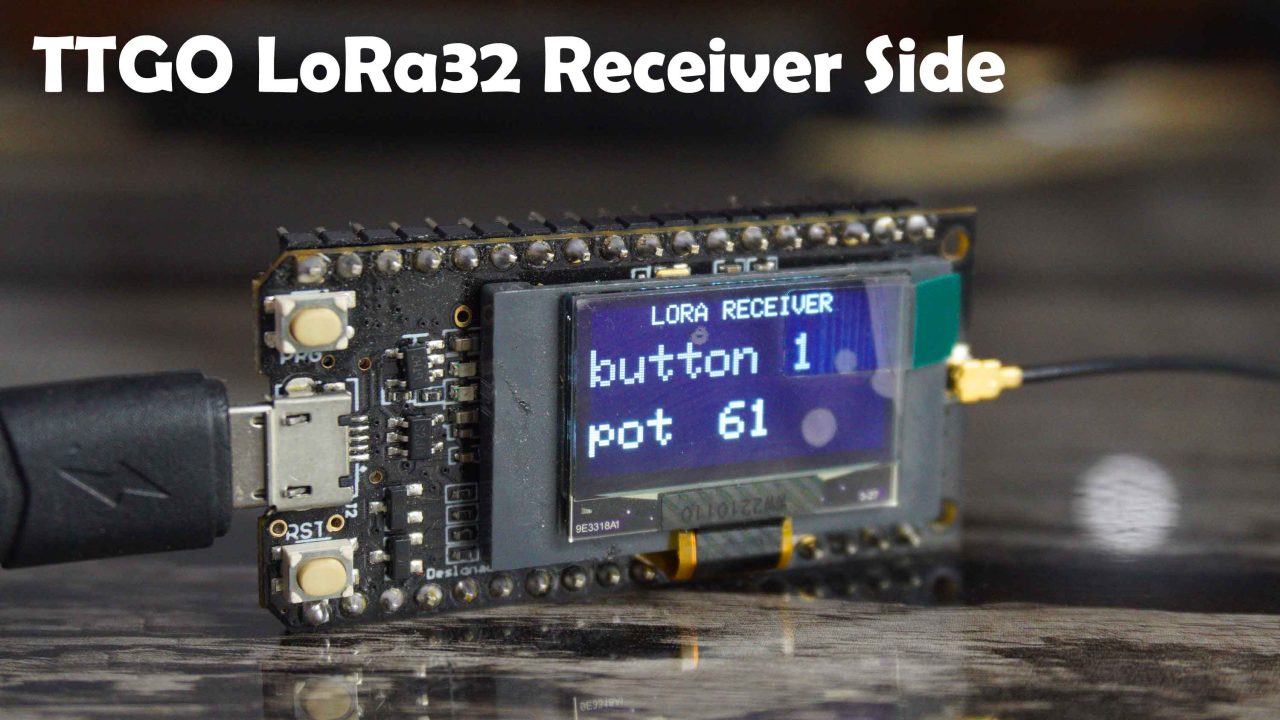
And you can also see the Potentiometer value which changes as I rotate the knob of the potentiometer. As you can see in the image below, the value changed from 61 to 4084 and I also changed the button state from 1 to 0 by pressing a button on the transmitter side.
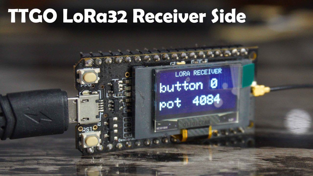
There is small latency “around 1 second” due to the delay used in the programming. You can reduce the delay if you want fast communication speed. So, its working. And now we are going to perform the range test.
LoRa32 Range Test:
TTGO LoRa32 Out of Sight Test:
During the first test, I kept the receiver side LoRa32 inside the room and I asked my brother to take the transmitter side outside. Because I wanted to check if the signals were powerful enough to penetrate through walls and different obstacles.
During this test, I was asking my brother about his location to find out how far these modules could communicate. Then, at one point, the communication stopped. When I checked on Google Maps, the distance was 77 meters. While the SX1278 communication range was 50 meters, the difference is 25meters, seriously I was expecting more. But anyway, during this test the LoRa32 is the winner.
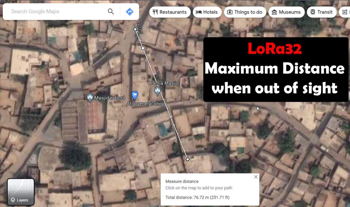
This is the distance when both LoRa modules are out of sight and there are walls and obstacles in between, as you can see in the image.
TTGO LoRa32 Line of sight Test:

Next, I came to this open location to perform the 2nd test. Let’s see from how far these LoRa32 modules can communicate when in line of sight.
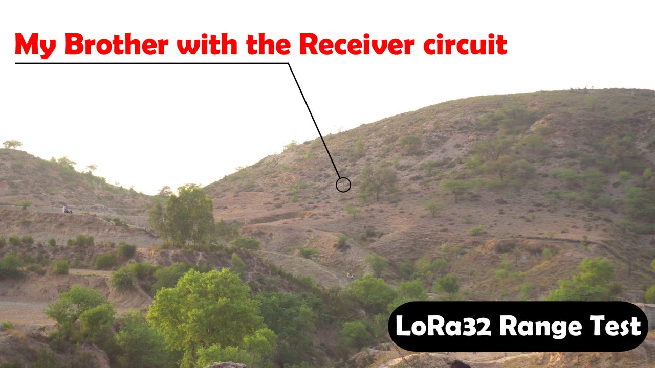
My brother is right there and he can receive the data. I was talking to him via cell phone. I checked the distance on google map and the distance was “428 meters“.
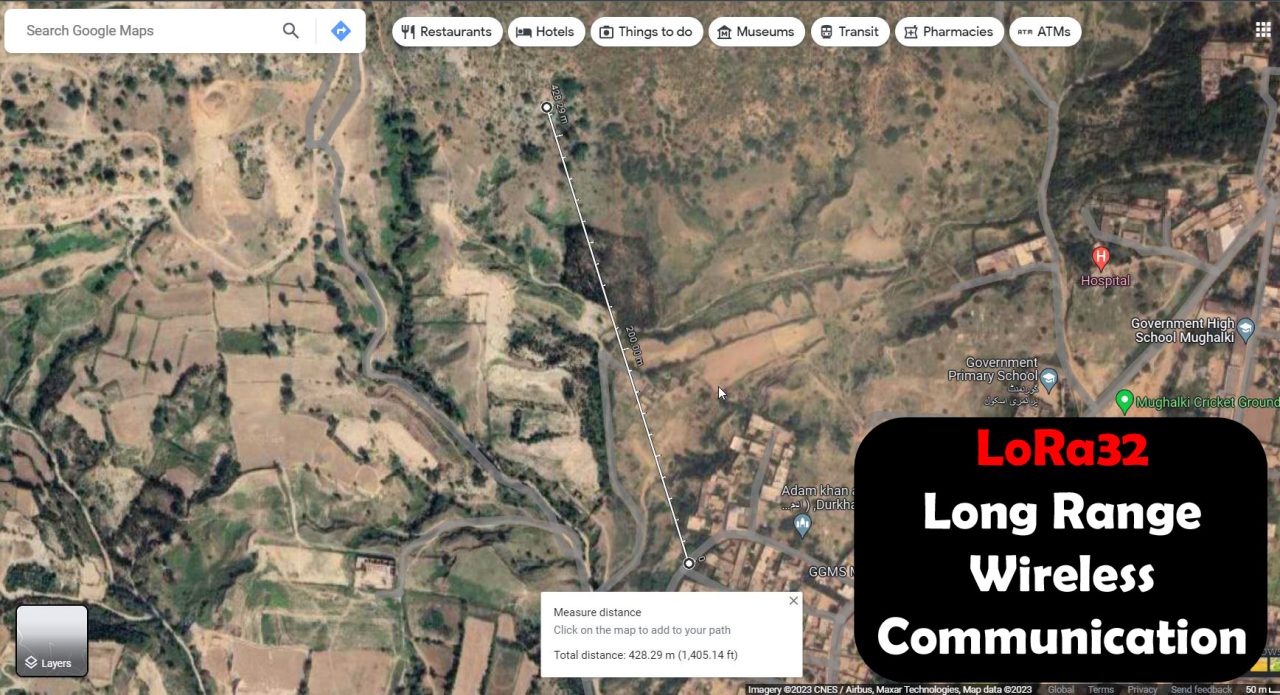
Next, I cam back to my home and right now I am on the roof and from here I can see the mountain.
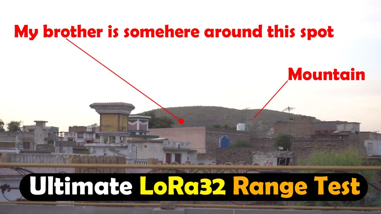
And the amazing thing is still he can receive the data. Although the modules are not completely line of sight but still its working. I think we are outside that’s why.
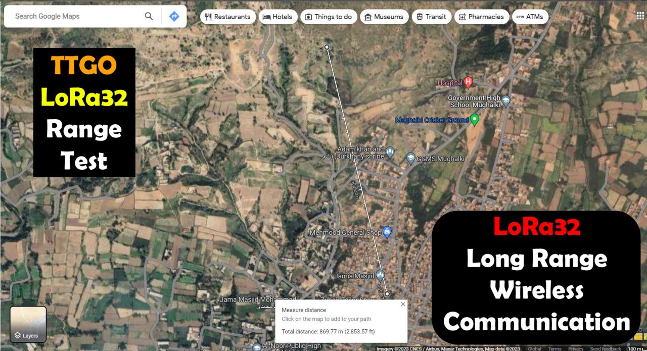
As you can see on Google Maps, the maximum communication range is “870meters“ this is simply amazing. Its such a long distance.
I am sure if these modules are installed at some height, they might be able to communicate over a long distnce even more than 1.5Km. And then you will be able to monitor your sensors, or control your electrical loads over such a long distance. So, that’s all for now.
Support me on Patreon for more videos I hope you like today’s episode. Like and share this video with your friends. See you in next episode and thanks for watching.
Watch Video Tutorial:
I get the following : Compilation error: no matching function for call to ‘TwoWire::begin(int, int)’
Can you help?